Table of Contents
Advertisement
Quick Links
Advertisement
Table of Contents

Related Manuals for Unitest TELARIS LOOP

Summary of Contents for Unitest TELARIS LOOP
- Page 1 ® UNITEST Instruction Manual Cat. No. 8978 TELARIS ® LOOP...
-
Page 3: Table Of Contents
Contents Contents Page 1.0 Introduction / Scope of Supply ..........4 2.0 Transport and Storage............4 3.0 Safety Measures ..............5 4.0 General Information ..............6 5.0 Display Indications / Control Elements ........7 6.0 Carrying out Measurements ..........8 6.1 Loop Measurement ..............8 6.2 Internal Mains Resistance Measurement........9 6.3 RPE/RN/RL Measurement............10 6.4 AC Voltage Measurement (VAC) ..........11 6.5 Frequency Measurement (f) ..........11... -
Page 4: Introduction / Scope Of Supply
Introduction / Scope of Supply / Transport and Storage References marked on instrument or in instruc- The instrument UNITEST TELARIS LOOP is charac- tion manual: terised by the following features: • A unit designed to allow the user to quickly esta-... -
Page 5: Safety Measures
3.0 Safety Measures The UNITEST TELARIS LOOP has been designed Avoid any heating up of the instrument by direct and checked in accordance with the safety regulati- sunlight to ensure perfect functioning and long ons for Electronic Test and Measurement Instru- instrument life. -
Page 6: General Information
The Loop impedance value is measured by Phase resistance short-term mains loading. RPE: Protective conductor resistance Additionally, the instrument TELARIS Loop allows Neutral conductor the user to test the mains internal resistance mea- Earth-Resistance surement (L-N). This measurement is not required... -
Page 7: Display Indications / Control Elements
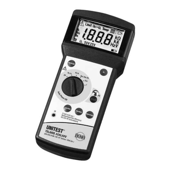
Display Indications and Control Elements 5.0 Display Indications and Control Elements Display Indications 1. Attention, warning symbol 2. “Limit”: exceeding the threshold value 3. “UB>UL”: contact voltage present exceeds the pre-set limit (25V or 50V) 4. “Temp”: internal temperature protection has triggered 5. -
Page 8: Carrying Out Measurements
Carrying out Measurements 6.0 Carrying out Measurements 6.1 Loop Impedance Measurement / Short-Circuit Current Measurement Prior to any measurement, test the instrument for perfect functioning by using a functional Connect the mains lead to the mains connector EUT. This could be a correctly wired socket of (13). -
Page 9: Internal Mains Resistance Measurement
Carrying out Measurements If the RN conductor resistance exceeds The socket is continuously monitored for per- 19.99Ω, the measurement is interrupted. The fect functioning. If the symbol (6) "reverse message "Attention (1) + Limit (2) + RN" is dis- mains plug” is displayed, the plug has to be tur- played. -
Page 10: Rpe/Rn/Rl Measurement
Carrying out Measurements 6.3 RPE / RN / RL Measurement If the value for RPE shows 0,00Ω this could be a Note of an exceeding interfering voltage. To obtain precise measurement results, switch off all loads or disconnect them from the mains. If a contact voltage UB is generated between N and PE during active measurement exceeding Connect the mains lead to the mains connector... -
Page 11: Ac Voltage Measurement (Vac)
Carrying out Measurements 6.4 AC Voltage Measurement 6.6 Contact Electrode Measurement of the present contact voltage is car- Never apply voltages exceeding 300V to input ried out after setting the contact voltage limit. By sockets. touching the contact electrode, exceeding the limit is automatically indicated (>25V or 50V). -
Page 12: Display Indications
Display Indications Resistance measurement 7.0 Display Indications Zl/ Ipsc ZL = 2,88 Ω All segments are illuminated Contact voltage limit 50 V Resistance measurement Zl/ Ipsc RL excessive (>19,99 Ω) The instrument is ready to Measurement is interrupted carry out measurements. Contact voltage limit 50 V Contact voltage limit 50V Resistance measurement... - Page 13 Storing Measurement Result 8.0 Storing Measurement Result turn plug Possibility to store measurement values by means turn plug / exchange L-N of the key „Store" (19) after completion of measu- rement. Altogether, 250 measurement values may be saved. Proceed as follows: Carry out measurement Frequency measurement f Read measurement value on display.
-
Page 14: Storing Measurements
Deleting stored Measurement Data / Maintenance 9.0 Deleting stored Measurement Data / 10.0 Energy Management Display of All Memory Entries Approximately 5 minutes after the last key operati- on, the instrument switches off automatically (auto- Possibility to delete data by using key „Clear" (21). power-off). -
Page 15: Battery Replacement
Battery Replacement / Calibration Interval 13.0 Battery Replacement Never try to disassemble battery cells. Never throw a battery into a fire as this could lead to Prior to battery replacement, disconnect the in- an explosion. Never expose batteries to humi- strument from the connected measurement dity circuits. -
Page 16: Technical Data
Technical Data 15.0 Technical Data Display: ..........LCD, 3 1/2 digit Reference range: ........+17°C ... 27°C, max. 70 % rel. humidity Mains voltage: ........230V + 10%/-15% Mains frequency: ........50-60 Hz Test current (ZL, RI, RN, RL, RPE): ..approx. 6 A/ 5mA for all resistance ranges applies: test current / time (RL, RN, RI): ....ca. - Page 17 Warranty Table with limit values for short-circuit currents for fuses according to DIN VDE 0636 characteristics gL: Nominal current Min. display for safe tripping Min. display for safe tripping during 5s (in Amps) during 0.2s (in Amps) 100A AC Voltage VAC Range Resolution Tolerance...
- Page 19 Qualitätszertifikat • Certificate of Quality Certificat de Qualité • Certificado de calidad Die BEHA-Gruppe bestätigt The BEHA Group confirms Le groupe BEHA déclare que El grupo BEHA declara que el hiermit, dass das erworbene herein that the unit you have l´appareil auquel ce document producto adquirido ha sido ca- Produkt gemäß...
- Page 20 24 month Warranty UNITEST instruments are subject to strict quality control. However, should the instrument function improperly during daily use, your are protected by our 24 months warranty (valid only with invoice). We will repair free of charge any defects in work- manship or material, provided the instrument is re- turned unopened and untampered i.e.
Need help?
Do you have a question about the TELARIS LOOP and is the answer not in the manual?
Questions and answers