Table of Contents
Advertisement
Quick Links
Advertisement
Table of Contents

Related Manuals for Bowa ARC 400


Summary of Contents for Bowa ARC 400
- Page 1 OPERATING MANUAL ELECTROSURGICAL UNIT...
- Page 2 Operating Manual ARC 400 900-400_IFU_V1.0.0.6.17.9_20140-S2-20130604-EN...
-
Page 3: Table Of Contents
Rear panel user interface components ............. 20 3.2. Symbols used on the device .................... 21 3.2.1. Rating label ....................... 22 3.3. Scope of delivery ......................22 3.4. Components required for operation ................. 22 3.5. Operating conditions ......................22 900-400_IFU_V1.0.0.6.17.9_20140-S2-20130604-EN Operating Manual ARC 400... - Page 4 5.4.9. Playing videos ....................42 5.5. Mode overview ......................... 43 5.5.1. Monopolar modes ..................... 43 5.5.2. Bipolar cutting modes ..................45 5.6. Monopolar cutting modes ....................46 5.6.1. Standard ......................46 5.6.2. Micro ......................... 46 Operating Manual ARC 400 900-400_IFU_V1.0.0.6.17.9_20140-S2-20130604-EN...
- Page 5 Bipolar scissors ....................60 5.9. Bipolar coagulation modes ....................61 5.9.1. Standard forceps ....................61 5.9.2. Standard forceps AUTO ................... 61 5.9.3. Micro forceps ....................62 5.9.4. Forceps forced ....................62 5.9.5. LIGATION ......................63 900-400_IFU_V1.0.0.6.17.9_20140-S2-20130604-EN Operating Manual ARC 400...
- Page 6 Repairs ..........................87 Storage ............................88 9.1. Technical service ......................88 Technical specifications ....................... 89 10.1. ARC 400 technical data ....................89 10.2. Output, voltage and current diagrams ................96 Accessories and replacement parts ..................134 EMC ............................... 135 12.1.
-
Page 7: Using This Operating Manual
Using this operating manual This operating manual is part of the device. BOWA-electronic GmbH & Co. KG, referred to in the following simply as BOWA, assume no liability nor provide any warranty whatsoever for damage and consequential damages that arise due to non-compliance with the operating manual. -
Page 8: Risk Levels In Warning Instructions
Activity with one step Activity with several steps in a binding sequence Result of preceding activity List (first level) List (second level) Emphasis Emphasis .., see Section xxx, page xxx Cross reference Operating Manual ARC 400 900-400_IFU_V1.0.0.6.17.9_20140-S2-20130604-EN... -
Page 9: Safety
BOWA requires that the HF device is operated under the supervision of qualified and authorized personnel. The surgeon and medical staff must be trained in the fundamental principles, rules for use and risks of HF surgery and must be familiar with these in order to safely and reliably prevent putting patients, staff and equipment at risk. -
Page 10: General Safety Instructions
In case of questions, please contact your local dealer or Technical Service, see section Technical service, page 88. To protect personnel, BOWA recommends the use of a smoke evacuator to extract electrosurgical smoke, e.g. BOWA SHE SHA. Operating Manual ARC 400... -
Page 11: Personal Safety Instructions
2.3.1. Ambient conditions Do not use the HF device in the immediate vicinity of the patient. Observe the minimum distances recommended by BOWA, as shown in the following figure. 2.3.2. Patients with pacemakers Malfunction or destruction of the pacemaker can endanger the life of the patient or result in irreversible injuries to the patient. -
Page 12: Hazard-Free Patient Positioning
Ensure that no conductive fluids (e.g. blood or amniotic fluid) have penetrated the foot switch or the manual switch. Ensure that the cables for the foot switch and the manual switch are free from short circuits and broken leads. Operating Manual ARC 400 900-400_IFU_V1.0.0.6.17.9_20140-S2-20130604-EN... -
Page 13: Configuring Hf Device Settings And Using Accessories
Do not remove hot electrodes from the patient’s body directly after cutting or coagulation. Ensure that there is sufficient distance between the patient cables and the cables of the HF device. Do not run the patient cable across the patient. 900-400_IFU_V1.0.0.6.17.9_20140-S2-20130604-EN Operating Manual ARC 400... -
Page 14: Product-Related Safety Instructions
2.4. Product-related safety instructions Devices manufactured by BOWA are developed in accordance with the current state of technology and generally accepted safety rules. Despite this, using these products can lead to risks to the life and health of the user or third parties and/or damage to the device or other objects. -
Page 15: Operation Area: Avoiding Ignition And Explosions
To prevent a rise in temperature at the current exit point, the following conditions must be ensured: sufficiently large contact surface between the neutral electrode and the patient’s body; high electrical conductivity between the neutral electrode and the patient’s body. 900-400_IFU_V1.0.0.6.17.9_20140-S2-20130604-EN Operating Manual ARC 400... - Page 16 Shave the area where the neutral electrode will be applied. Clean the application site, but do not use any alcohol, since it dries out the skin and increases the contact resistance. If the patient has poor circulation, massage or brush the application site. Operating Manual ARC 400 900-400_IFU_V1.0.0.6.17.9_20140-S2-20130604-EN...
- Page 17 HF device may detect a path between the two sections due to other objects. See that the current flows equally to both parts of the split neutral electrode. See Section Fault indications for EASY monitoring, page 84 regarding monitoring of the neutral electrode. 900-400_IFU_V1.0.0.6.17.9_20140-S2-20130604-EN Operating Manual ARC 400...
-
Page 18: Description
Socket connector for monopolar instruments with hand or foot switch* Socket connector for monopolar instruments with hand or foot switch* Socket connector for neutral electrode * * Applied part type F according to IEC 60601-1 Operating Manual ARC 400 900-400_IFU_V1.0.0.6.17.9_20140-S2-20130604-EN... -
Page 19: Bipolar Connector Module (Right)
4-mm socket (for foot switch) Connection socket for neutral electrode Neutral (US type) 3.1.3. Bipolar connector module (right) Socket connector for bipolar instruments with foot switch or AUTOSTART* Socket connector for bipolar instruments with foot switch or AUTOSTART* 900-400_IFU_V1.0.0.6.17.9_20140-S2-20130604-EN Operating Manual ARC 400... -
Page 20: Rear Panel User Interface Components
Use the following connections only for service and training purposes: Ethernet connector USB connector Audio In (not occupied) UART communication interface The USB connector can be used to perform software updates. The maximum voltage at the SIP/SOP ports is 15 V Operating Manual ARC 400 900-400_IFU_V1.0.0.6.17.9_20140-S2-20130604-EN... -
Page 21: Symbols Used On The Device
Directive 2002/96/EC (WEEE); see "Disposal" (Active) HF output; caution: hazardous voltage Manufacturer Date of manufacture Observe use instructions Equipotentiality connection Fiber-optic signal input Fiber-optic signal output Ethernet connector USB connector Audio In UART communication interface 900-400_IFU_V1.0.0.6.17.9_20140-S2-20130604-EN Operating Manual ARC 400... -
Page 22: Rating Label
3 Description 3.2.1. Rating label Figure 3-1: ARC 400 rating label 3.3. Scope of delivery You'll find detailed information on the scope of delivery in the current catalogs. 3.4. Components required for operation Power cable Foot switch ... -
Page 23: Prearrangement
3. Place the HF device a sufficient distance away from other electronic equipment, see Section EMC, page 135. 4. Position the HF device with the front of the device facing the patient and surgeon. 5. Do not place any other device on the HF device. 900-400_IFU_V1.0.0.6.17.9_20140-S2-20130604-EN Operating Manual ARC 400... -
Page 24: Switching On The Hf Device
The insulation of the accessories (e.g. HF cables and instruments) must be sufficient for the maximum peak output voltage (see IEC 60601-2-2 and IEC 60601-2-18). Do not use accessories with defective insulation. Operating Manual ARC 400 900-400_IFU_V1.0.0.6.17.9_20140-S2-20130604-EN... -
Page 25: Instruments For Monopolar Use
The following foot switch systems can be connected to the HF device: Item no. Designation 901-011 Single-pedal foot switch with switch 901-031 Double-pedal foot switch with switch 901-032 Double-pedal foot switch with switch and clip 900-400_IFU_V1.0.0.6.17.9_20140-S2-20130604-EN Operating Manual ARC 400... -
Page 26: Functional Test
6. Select a mode with AUTOSTART, grasp moist gauze with the forceps, and check the display. 7. Now change to a mode without AUTOSTART and use the footswitch to activate the bipolar output. Check the settings and indicators in the bipolar section. Operating Manual ARC 400 900-400_IFU_V1.0.0.6.17.9_20140-S2-20130604-EN... -
Page 27: Actions In Case Of Problems
4.5.1. General information BOWA recommends using split neutral electrodes, since only this type of electrode allows the HF device to detect detachment of the neutral electrode if this occurs. Monitoring of the neutral electrode minimizes the risk of burns at the site where the neutral electrode is attached. -
Page 28: Easy Neutral Electrode Monitoring (Easy Monitoring)
NOTE Risk of incorrect application of the neutral electrode Ensure compliance with the specifications for correct attachment of the neutral electrode with regard to size, adhesive properties and full-surface contact of the complete electrode. Operating Manual ARC 400 900-400_IFU_V1.0.0.6.17.9_20140-S2-20130604-EN... -
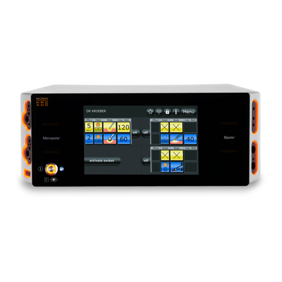
Page 29: Operation
The "Pedal" button allows the activation of specific functions to be assigned to the foot pedal. The "Mode" button allows the desired type of current to be selected. The "max. Watt" button is used to set the maximum output power. 900-400_IFU_V1.0.0.6.17.9_20140-S2-20130604-EN Operating Manual ARC 400... -
Page 30: Status Bar
Unused socket The socket illumination extinguishes and connector lights up when an instrument is plugged in. To hide the selection, press the "off" button next to the connector settings overview. Figure 5-6: Activated socket Operating Manual ARC 400 900-400_IFU_V1.0.0.6.17.9_20140-S2-20130604-EN... -
Page 31: Configuring Output Currents
5. Additional selection options are available in the selection window. To select indication-related modes, press the “Indications” button. 6. Confirm your selection by pressing the "OK" button. The main screen will be displayed. - or - 900-400_IFU_V1.0.0.6.17.9_20140-S2-20130604-EN Operating Manual ARC 400... -
Page 32: Specifying Power Limits
3. Press the "?" button for more information on this selection. 4. Confirm your selection by pressing the "OK" button. - or - Press the "Back" button to return to the main screen without changing the selection. Operating Manual ARC 400 900-400_IFU_V1.0.0.6.17.9_20140-S2-20130604-EN... -
Page 33: Selecting The Effect
3. Press the "?" button for more information on this selection. 4. Confirm your selection by pressing the "OK" button. - or - Press the "back" button to return to the main screen without changing the selection. 900-400_IFU_V1.0.0.6.17.9_20140-S2-20130604-EN Operating Manual ARC 400... -
Page 34: Assigning The Foot Pedal
The socket is assigned to the active pedal level. 4. Pedal levels can be changed using the foot switches. Press the orange button to change the socket. The orange background indicates that the lower left-hand socket is activated. Operating Manual ARC 400 900-400_IFU_V1.0.0.6.17.9_20140-S2-20130604-EN... - Page 35 5 Operation Figure 5-11: Foot switch changeover If two footswitches are connected, either a single-pedal footswitch or a double-pedal footswitch can be selected for coagulation. Figure 5-12: Foot switch selection coagulation 900-400_IFU_V1.0.0.6.17.9_20140-S2-20130604-EN Operating Manual ARC 400...
- Page 36 Double pedal foot Double pedal foot switch not switch not connected connected Single pedal foot Single pedal foot switch COAG switch not active connected Single pedal foot Deactivate foot switch COAG switch inactive Operating Manual ARC 400 900-400_IFU_V1.0.0.6.17.9_20140-S2-20130604-EN...
-
Page 37: Mode Change
2. To change the mode to coagulation, touch the “Mode change” button. Now three bipolar connections are at your disposal. An indicator of the mode change is shown next to the button „Effect“. Figure 5-14: Double operation lower bipolar socket 900-400_IFU_V1.0.0.6.17.9_20140-S2-20130604-EN Operating Manual ARC 400... -
Page 38: Selecting The Neutral Electrode
The selected type of neutral electrode in connection with a colour-indicator for the contact quality is shown in the status bar. When using the „EASY“ and „BABY“ mode, no unsplit electrodes are accepted. Using the „MONO“ mode, no split electrodes are accepted. Operating Manual ARC 400 900-400_IFU_V1.0.0.6.17.9_20140-S2-20130604-EN... - Page 39 Display contact connected / quality recognised Split baby neutral electrode contact quality OK Split baby neutral electrode contact quality not optimum Split baby neutral electrode contact quality insufficient Split baby neutral electrode not connected / recognised 900-400_IFU_V1.0.0.6.17.9_20140-S2-20130604-EN Operating Manual ARC 400...
-
Page 40: 5.4.7.Dr. Dongle
Dr. Dongle is an individual memory stick on which up to six programs can be saved for subsequent use. Insert your Dr. Dongle with your personal settings into every ARC 400 at any bipolar socket. The data is read as soon as you insert Dr. Dongle or after changing a program with Dr. -
Page 41: Plug'n Cut Comfort
5 Operation Save current program on Dr. Dongle: The program currently loaded in ARC 400 can be saved on Dr. Dongle: 1. In the overview, select a program storage space to be overwritten. 2. Press “save” to save the currently loaded program at the selected space. -
Page 42: Playing Videos
The permissible parameters for the BOWA COMFORT instrument remain accessible; all other modes are greyed out. 5.4.9. Playing videos 1. Plug the delivered BOWA USB stick into the connection on the rear side of the ARC 400. 2. Switch the unit on. ... -
Page 43: Mode Overview
Argon open* GastroCut Argon flexible* Loop slow GastroCut Argon flex. pulse* Loop medium GastroCut Gastro Coag Loop fast * These modes can only be used in connection with the argon coagulation unit ARC PLUS (900-001). 900-400_IFU_V1.0.0.6.17.9_20140-S2-20130604-EN Operating Manual ARC 400... - Page 44 5 Operation Bildzeichen Bildzeichen Modus Modus Bezeichnung Bezeichnung Schneiden Koagulieren GastroCut Resection Knife slow GastroCut Cardiac Mammary Knife medium GastroCut Cardiac Thorax Knife fast SimCoag Operating Manual ARC 400 900-400_IFU_V1.0.0.6.17.9_20140-S2-20130604-EN...
-
Page 45: Bipolar Cutting Modes
Depending on individual conditions, it may be necessary to deviate from the provided data. Medical practice is continuously evolving as a result of R&D and clinical experience. This may also make deviations from the provided data necessary. 900-400_IFU_V1.0.0.6.17.9_20140-S2-20130604-EN Operating Manual ARC 400... -
Page 46: Monopolar Cutting Modes
Micro This mode is used for electrosurgical cutting using micro-electrodes. It enables extremely fine control of the power level and precise work. Application areas Pediatric surgery, neurosurgery, plastic surgery Suitable instruments Micro needle electrodes Operating Manual ARC 400 900-400_IFU_V1.0.0.6.17.9_20140-S2-20130604-EN... -
Page 47: Dry
This mode is used to perform open surgical interventions in combination with the ARC PLUS companion device for argon-assisted cutting. With suitable instruments connected, argon-assisted cutting can be performed using rigid electrodes. Application areas Visceral surgery Suitable instruments Rigid argon electrodes Argon handpiece 900-400_IFU_V1.0.0.6.17.9_20140-S2-20130604-EN Operating Manual ARC 400... -
Page 48: Resection
This mode is used in gynecology for laparoscopic hysterectomy. Removal of the uterus can be achieved by applying monopolar cutting current and pulling on the sling at the same time. Application areas Gynecology; laparoscopic hysterectomy Suitable instruments Gynecological slings Operating Manual ARC 400 900-400_IFU_V1.0.0.6.17.9_20140-S2-20130604-EN... -
Page 49: Laparoscopy
With a relatively slow pulse rate of 1 cutting pulse per second, this mode is suitable for especially cautious work. Application areas Polyp removal using polypectomy snares and flexible endoscopy Suitable instruments Polypectomy snares 900-400_IFU_V1.0.0.6.17.9_20140-S2-20130604-EN Operating Manual ARC 400... -
Page 50: Gastrocut Loop Medium
With an accelerated fast pulse rate of 3.2 - 5 cutting pulses per second, this mode is suitable for advanced users. Application areas Polyp removal using polypectomy snares and flexible endoscopy, with accelerated fast pulse rate for advanced users. Suitable instruments Polypectomy snares Operating Manual ARC 400 900-400_IFU_V1.0.0.6.17.9_20140-S2-20130604-EN... -
Page 51: Gastrocut Knife Slow
1.7 cutting pulses per second, this mode is suitable for experienced users. Application areas Papilla incision using a papillotome and flexible endoscopy, resection with needle knives; accelerated pulse rate for experienced users. Suitable instruments Papillotome Needle knives 900-400_IFU_V1.0.0.6.17.9_20140-S2-20130604-EN Operating Manual ARC 400... -
Page 52: Gastrocut Knife Fast
"Effect" setting in the range of 1 to 3. Application areas Coagulation with relatively high penetration depth; low electrode adhesion to tissue Suitable instruments Electrodes with large contact areas, such as ball electrodes Operating Manual ARC 400 900-400_IFU_V1.0.0.6.17.9_20140-S2-20130604-EN... -
Page 53: Forced Non Cutting
It achieves a high degree of coagulation with moderate cutting tendency. Application areas Fast coagulation with small penetration depth and moderate cutting tendency Suitable instruments Knife electrodes Spatula electrodes Insulated monopolar forceps 900-400_IFU_V1.0.0.6.17.9_20140-S2-20130604-EN Operating Manual ARC 400... -
Page 54: Forced Cutting
Application areas Promoting coagulation of diffuse bleeding Suitable instruments Ball electrodes Knife electrodes Spatula electrodes Needle electrodes Operating Manual ARC 400 900-400_IFU_V1.0.0.6.17.9_20140-S2-20130604-EN... -
Page 55: Argon Open
This mode is used for argon-assisted electrosurgery in conjunction with the ARC PLUS accessory device. This is the current type Spray. For argon-assisted coagulation, flexible probes are used in combination with endoscopes. Application areas Gastroenterology, homogeneous surface coagulation Suitable instruments Flexible argon probes 900-400_IFU_V1.0.0.6.17.9_20140-S2-20130604-EN Operating Manual ARC 400... -
Page 56: Argon Flex. Pulse
This mode is used for monopolar hemostasis in gynecology and urology. Use non-conductive irrigation fluids. Application areas Hysteroscopy, transurethral prostate resection (TUR-P), surgical treatment of bladder tumors (TUR-B), vaporization of prostate tissue (TUR-VAP). Suitable instruments Resectoscope (monopolar) Resection sling Rollerblade electrode Operating Manual ARC 400 900-400_IFU_V1.0.0.6.17.9_20140-S2-20130604-EN... -
Page 57: Cardiac Mammary
Application areas Mammary surgery and cardiac surgery Suitable instruments Knife electrodes 5.7.10. Cardiac Thorax This mode is used in thoracic surgery. It produces forced coagulation. Application areas Thoracic surgery Suitable instruments Knife electrodes 900-400_IFU_V1.0.0.6.17.9_20140-S2-20130604-EN Operating Manual ARC 400... -
Page 58: Simcoag
Spatula electrodes 5.7.12. Gastro Coag This mode is used in gastroenterology with contact coagulation for the coagulation of small areas. Application areas After bleeding associated with polypectomies or papillotomies. Suitable instruments Polypectomy snares Papillotome Operating Manual ARC 400 900-400_IFU_V1.0.0.6.17.9_20140-S2-20130604-EN... -
Page 59: Laparoscopy
Laparoscopy, arthroscopy Suitable instruments Arthroscopy electrodes Laparoscopy electrodes 5.8. Bipolar cutting modes 5.8.1. Standard This mode is used for cutting with bipolar laparoscopic instruments. Application areas Laparoscopic cutting Suitable instruments Laparoscopic instruments 900-400_IFU_V1.0.0.6.17.9_20140-S2-20130604-EN Operating Manual ARC 400... -
Page 60: Bipolar Resection
Resectoscope (bipolar) Resection sling Rollerblade electrode Optimum results are provided exclusively when using BOWA COMFORT resection cables. 5.8.3. Bipolar scissors This mode is used with bipolar scissors. It can be used for coagulation before or during cutting, point coagulation, coagulation of cuts and surface coagulation. -
Page 61: Bipolar Coagulation Modes
MENU – SYSTEM SETTINGS – AUTOSTART DELAY. Setting the AUTOSTART mode can result in unintentional coagulations, e.g. when bipolar forceps are used for gripping while the AUTOSTART Mode is on. Application areas Bipolar coagulation with AUTOSTART Suitable instruments Bipolar forceps 900-400_IFU_V1.0.0.6.17.9_20140-S2-20130604-EN Operating Manual ARC 400... -
Page 62: Micro Forceps
Bipolar coagulation in pediatric surgery, neurosurgery, plastic surgery, etc. Suitable instruments Bipolar forceps Micro forceps 5.9.4. Forceps forced This mode is used for forced coagulation with forceps. Application areas Fast bipolar coagulation Suitable instruments Bipolar forceps Operating Manual ARC 400 900-400_IFU_V1.0.0.6.17.9_20140-S2-20130604-EN... -
Page 63: Ligation
TissueSeal PLUS for open surgical applications. Conventional instruments cannot be used in this mode. The output power is preconfigured and automatically regulated. Application areas Vessel sealing in open surgery Suitable instrument ® TissueSeal PLUS 900-400_IFU_V1.0.0.6.17.9_20140-S2-20130604-EN Operating Manual ARC 400... -
Page 64: Bipolar Scissors
Bipolar scissors should only be operated with the current type bipolar scissors cutting or bipolar scissors coagulation. 5.9.8. Laparoscopy This mode is used for coagulation in combination with bipolar laparoscopic instruments. Application areas Laparoscopic coagulation Suitable instruments Laparoscopic instruments Operating Manual ARC 400 900-400_IFU_V1.0.0.6.17.9_20140-S2-20130604-EN... -
Page 65: Bipolar Resection
(TUR-B), vaporization of prostate tissue (TUR-VAP) Suitable instruments Resectoscope Resection sling Rollerblade electrode Make sure that the instrument has contact with the tissue while activating bipolar coagulation to avoid an unintended heating of the irrigation fluid. 900-400_IFU_V1.0.0.6.17.9_20140-S2-20130604-EN Operating Manual ARC 400... -
Page 66: Menu Dialogs
The following menu dialogs are available: Figure 5-19: Menu dialogs Selecting a dialog Press the button of the desired dialog to launch the program. Exiting a dialog Press the "back" button to return to the main screen. Operating Manual ARC 400 900-400_IFU_V1.0.0.6.17.9_20140-S2-20130604-EN... -
Page 67: System Settings" Dialog
Use the "Volume" dialog to set the volume of the individual acoustic signals. Figure 5-21: "Sound Level" dialog Incremental setting Press the "+" and "-" buttons. Fast setting Move the slider in the desired direction. 900-400_IFU_V1.0.0.6.17.9_20140-S2-20130604-EN Operating Manual ARC 400... -
Page 68: System Messages" Dialog
2. Use the arrow buttons to select the desired chapter. 3. Press to open the selected chapter. " " Use the arrow buttons to open the individual pages of the chapter. 4. Press back to return to the chapter overview. " " Operating Manual ARC 400 900-400_IFU_V1.0.0.6.17.9_20140-S2-20130604-EN... -
Page 69: Bowa Service" Dialog
"System messages" dialog 5.10.5. "BOWA Service" dialog After entering a password, you can use the "BOWA Service" dialog to access additional options, such as resetting the device to the factory default configuration or viewing the instructions of use. Moreover, the software version and the next TSI date is displayed, see chapter Safety inspection, page 86. -
Page 70: Select Program" Dialog
Figure 5-24: "Select program" dialog Up to eight programs can be put on the favourites list. If the eight places are full and a new program is being assigned to the favourites, the following screen is shown. Operating Manual ARC 400 900-400_IFU_V1.0.0.6.17.9_20140-S2-20130604-EN... -
Page 71: Delete Program" Dialog
Vertical and horizontal navigation is also possible via the arrow buttons 2. Press the "recycle bin" button to fully delete the selected program. The selected program will be deleted without any further prompt. The default program appears. The default program cannot be deleted. 900-400_IFU_V1.0.0.6.17.9_20140-S2-20130604-EN Operating Manual ARC 400... -
Page 72: Favourites" Dialog
With a keypad texts program names can be created. Several symbols, capital or small letters or numbers are selection options. Confirm with "OK" to accept the selection. To return to the main screen click on "back". Operating Manual ARC 400 900-400_IFU_V1.0.0.6.17.9_20140-S2-20130604-EN... -
Page 73: 5.10.10. "Argon" Dialog
Press the "Back" button to return to the main screen without changing the selection. Default settings for argon flow rates according to the different modes are selected automatically: Argon open: CUT flow rate: 4.0 l/min COAG flow rate: 3.0 l/min Argon flexible: COAG flow rate: 0.4 l/min 900-400_IFU_V1.0.0.6.17.9_20140-S2-20130604-EN Operating Manual ARC 400... -
Page 74: Basic Programs
5 Operation 5.11. Basic programs The following basic programs are provided with the full version of ARC 400 (incl. the resection bipolar option and the LIGATION option): 3 Bipolar Argon flex Argon Cardiac GastroCut ... - Page 75 5 Operation Figure 5-31: Basic program "Argon flex" Figure 5-32: Basic program "Argon" Figure 5-33: Basic program "Cardiac" 900-400_IFU_V1.0.0.6.17.9_20140-S2-20130604-EN Operating Manual ARC 400...
- Page 76 5 Operation Figure 5-34: Basc program "GastroCut" Figure 5-35: Basic program "Laparoscopy" LIGATION is only available in this program with the LIGATION option. Figure 5-36: Basic program "Macro" Operating Manual ARC 400 900-400_IFU_V1.0.0.6.17.9_20140-S2-20130604-EN...
- Page 77 5 Operation Figure 5-37: Basic program "Micro" Figure 5-38: Basic program "Open Surgery" Figure 5-39: Basic program "Resection bipolar" This program is only available with the resection bipolar option. 900-400_IFU_V1.0.0.6.17.9_20140-S2-20130604-EN Operating Manual ARC 400...
- Page 78 5 Operation Figure 5-40: Basic program "Resection monopolar" Figure 5-41: Basic program "SimCoag" Figure 5-42: Basic program "Standard" Operating Manual ARC 400 900-400_IFU_V1.0.0.6.17.9_20140-S2-20130604-EN...
-
Page 79: Detecting And Correcting Faults
While an error is present, activations are prohibited. The message is available using the orange marked „?“ in the system bar. Moreover, these messages are available in the menu program system settings and will be deleted when switching off the unit. 900-400_IFU_V1.0.0.6.17.9_20140-S2-20130604-EN Operating Manual ARC 400... - Page 80 Choose another socket for this mode. Foot Switch Error Foot switch not assigned to a socket. The foot switch has not been assigned to a socket yet. Assign a socket to the foot switch using the "Pedal" button. Operating Manual ARC 400 900-400_IFU_V1.0.0.6.17.9_20140-S2-20130604-EN...
- Page 81 Foot Switch Error Fault on foot switch connection. Check the foot switch. If this message appears again, please contact the Technical Support. Internet: www.bowa.de Telephone: +49707260020 Finger Switch Error Fault on finger switch connection.
- Page 82 Subsequently restart ARC PLUS by activating the flashing "Purge" button. ARC PLUS Warning Please check if the argon bottles are connected and open. Empty bottles should be replaced. Subsequently restart ARC PLUS by activating the flashing "Purge" button. Operating Manual ARC 400 900-400_IFU_V1.0.0.6.17.9_20140-S2-20130604-EN...
- Page 83 If repeated purging does not solve the problem, the instrument and cable must be replaced. ARC PLUS Warning The argon flow settings at ARC 400 are invalid ARC PLUS Warning The filling level of the argon bottle is low. Please make sure that a replacement is available.
-
Page 84: Fault Indications For Easy Monitoring
Check the neutral electrode cable for proper connection and external damage. Reattach the neutral Loosened electrode An acoustic electrode. If the fault signal sounds. persists, replace the neutral A warning electrode. message appears on the display Operating Manual ARC 400 900-400_IFU_V1.0.0.6.17.9_20140-S2-20130604-EN... -
Page 85: Preparation
Disinfection and cleaning NOTE Incorrect handling of the HF device can cause damage to the unit! Never sterilize the ARC 400 device. Instead, clean or disinfect it. WARNING Risk of electric shock and fire! Unplug the power connection before cleaning the device. -
Page 86: Maintenance And Repair
8.1.1.Safety inspection Safety inspections must be performed once a year. The next safety inspection date of ARC 400 can be displayed in the dialog, see “BOWA Service” dialog, page 69 A warning message appears during system start-up if a safety inspection is due. -
Page 87: Repairs
If a repair is necessary, have it done only by the service center specified below. Never carry out any repairs yourself. BOWA is liable for safety, reliability and performance of the HF device under the following conditions: Full compliance with all instructions regarding the installation and proper use for the intended purpose contained in this operating manual was maintained. -
Page 88: Storage
Atmospheric pressure: 500 to 1600 hPa 9.1. Technical service Contact the following service center for maintenance and repair work: BOWA-electronic GmbH & Co. KG Heinrich-Hertz-Strasse 4–10 72810 Gomaringen, Germany Phone +49 (0) 7072-6002-0 Fax +49 (0) 7072-6002-33 Email service@bowa.de or visit our website: www.bowa.de... -
Page 89: Technical Specifications
10 Technical specifications Technical specifications 10.1. ARC 400 technical data Insulation type / Classification IEC 60601-1-2 Level of protection provided by the housing IP 21 Protection class according to EN 60601-1 Application component type according to EN 60601-1 Standards compliance... - Page 90 System faults shown on the display further information Documentation Data acquisition and storage in the device System information with date Fault states Operating errors Data retrieval via the display Text messages with further information Operating Manual ARC 400 900-400_IFU_V1.0.0.6.17.9_20140-S2-20130604-EN...
- Page 91 Communication External interface for communication with ARC PLUS (light wire cables) USB interface for software updates External PC interface, UART, using BOWA software Service support using BOWA software Service support Network port for service support ...
- Page 92 650 Vp constant 700 Vp 700 Vp 700 Vp 750 Vp sinusoidal alternating GastroCut Coag, Cut 750 Vp Loop slow and break phases sinusoidal alternating GastroCut Coag, Cut 750 Vp Loop medium and break phases Operating Manual ARC 400 900-400_IFU_V1.0.0.6.17.9_20140-S2-20130604-EN...
- Page 93 3.8 kVp Spray 1 W - 120 W modulated 4.6 kVp 5.0 kVp pulsed Argon open 1 W - 120 W 4.6 kVp modulated pulsed Argon flexible 1 W - 120 W 4.4 kVp modulated 900-400_IFU_V1.0.0.6.17.9_20140-S2-20130604-EN Operating Manual ARC 400...
- Page 94 1 W - 120 W 200 Vp scissors constant Modes Bipolar Coagulation Standard sinusoidal 1 W - 120 W 150 Vp forceps constant Standard sinusoidal forceps 5 W - 120 W 150 Vp constant AUTO Operating Manual ARC 400 900-400_IFU_V1.0.0.6.17.9_20140-S2-20130604-EN...
- Page 95 200 Vp scissors constant sinusoidal Laparoscopy 1 W - 120 W 150 Vp constant Bipolar sinusoidal 1 W - 350 W 190 Vp resection constant The max. values are not necessarily created at rated load resistance. 900-400_IFU_V1.0.0.6.17.9_20140-S2-20130604-EN Operating Manual ARC 400...
-
Page 96: Output, Voltage And Current Diagrams
"Monopolar Cutting Standard" Rated load resistance = 500 Table of HF output voltage U [Vp] as a function of the setting "Monopolar Cutting Standard" (idle mode) Pos : 53 /679-BOWA/HF- Ger äte/ARC 300/ Operating Manual ARC 400 900-400_IFU_V1.0.0.6.17.9_20140-S2-20130604-EN... - Page 97 Diagram of power output P [W] as a function of the setting "Monopolar Cutting Micro" Rated load resistance = 500 Table of HF output voltage U [Vp] as a function of the setting "Monopolar Cutting Micro" (idle mode) 900-400_IFU_V1.0.0.6.17.9_20140-S2-20130604-EN Operating Manual ARC 400...
- Page 98 Diagram of power output P [W] as a 1600 function of the setting "Monopolar Cutting Dry" 1600 Rated load resistance = 500 Table of HF output voltage U [Vp] as a function of the setting "Monopolar Cutting Dry" (idle mode) Operating Manual ARC 400 900-400_IFU_V1.0.0.6.17.9_20140-S2-20130604-EN...
- Page 99 Diagram of power output P [W] as a function of the setting "Monopolar Cutting Argon" Rated load resistance= 500 Table of HF output voltage U [Vp] as a function of the setting "Monopolar Cutting Argon" (idle mode) 900-400_IFU_V1.0.0.6.17.9_20140-S2-20130604-EN Operating Manual ARC 400...
- Page 100 Table of power output P [W] as a Table of HF output voltage U [Vp] as function of the setting "Monopolar a function of the setting "Monopolar Cutting Resection" Cutting Resection" (idle mode) Rated load resistance= 500 Operating Manual ARC 400 900-400_IFU_V1.0.0.6.17.9_20140-S2-20130604-EN...
- Page 101 Table of power output P [W] as a function Table of HF output voltage U [Vp] as a of the setting "Monopolar Cutting function of the setting "Monopolar MetraLOOP" Cutting MetraLOOP" (idle mode) Rated load resistance= 500 900-400_IFU_V1.0.0.6.17.9_20140-S2-20130604-EN Operating Manual ARC 400...
- Page 102 Diagram of power output P [W] as a function of the setting "Monopolar Cutting Laparoscopy" Rated load resistance= 500 Table of HF output voltage U [Vp] as a function of the setting "Monopolar Cutting Laparoscopy" (idle mode) Operating Manual ARC 400 900-400_IFU_V1.0.0.6.17.9_20140-S2-20130604-EN...
- Page 103 Table of HF output voltage U [Vp] as a Table of power output P [W] as a function of the setting "Monopolar function of the setting "Monopolar Cutting GastroCut Loop slow" Cutting GastroCut Loop slow" (idle mode) Rated load resistance= 500 900-400_IFU_V1.0.0.6.17.9_20140-S2-20130604-EN Operating Manual ARC 400...
- Page 104 Table of HF output voltage U [Vp] as a Table of power output P [W] as a function of the setting "Monopolar function of the setting "Monopolar Cutting GastroCut Loop medium" Cutting GastroCut Loop medium" (idle mode) Rated load resistance= 500 Operating Manual ARC 400 900-400_IFU_V1.0.0.6.17.9_20140-S2-20130604-EN...
- Page 105 Table of HF output voltage U [Vp] as a Table of power output P [W] as a function of the setting "Monopolar function of the setting "Monopolar Cutting GastroCut Loop fast" Cutting GastroCut Loop fast" (idle mode) Rated load resistance= 500 900-400_IFU_V1.0.0.6.17.9_20140-S2-20130604-EN Operating Manual ARC 400...
- Page 106 Table of HF output voltage U [Vp] as a Table of power output P [W] as a function of the setting "Monopolar function of the setting "Monopolar Cutting GastroCut Knife slow" Cutting GastroCut Knife slow" (idle mode) Rated load resistance= 500 Operating Manual ARC 400 900-400_IFU_V1.0.0.6.17.9_20140-S2-20130604-EN...
- Page 107 Table of HF output voltage U [Vp] as a Table of power output P [W] as a function of the setting "Monopolar function of the setting "Monopolar Cutting GastroCut Knife medium" Cutting GastroCut Knife medium" (idle mode) Rated load resistance= 500 900-400_IFU_V1.0.0.6.17.9_20140-S2-20130604-EN Operating Manual ARC 400...
- Page 108 Table of HF output voltage U [Vp] as a Table of power output P [W] as a function of the setting "Monopolar function of the setting "Monopolar Cutting GastroCut Knife fast" Cutting GastroCut Knife fast" (idle mode) Rated load resistance= 500 Operating Manual ARC 400 900-400_IFU_V1.0.0.6.17.9_20140-S2-20130604-EN...
- Page 109 Table of HF output voltage U [Vp] as a function of the setting "Monopolar Coagulation Moderate" (idle mode) Diagram of power output P [W] as a function of the setting "Monopolar Coagulation Moderate" Rated load resistance= 75 900-400_IFU_V1.0.0.6.17.9_20140-S2-20130604-EN Operating Manual ARC 400...
- Page 110 HF output voltage U [Vp] for the setting "Monopolar Coagulation Moderate" (idle mode) = 3500 Vp Diagram of power output P [W] as a function of the setting "Monopolar Coagulation Forced non cutting" Rated load resistance = 1000 Operating Manual ARC 400 900-400_IFU_V1.0.0.6.17.9_20140-S2-20130604-EN...
- Page 111 Table of HF output voltage U [Vp] as a function of the setting "Monopolar Coagulation Forced mixed" (idle mode) Diagram of power output P [W] as a function of the setting "Monopolar Coagulation Forced mixed" Rated load resistance = 500 900-400_IFU_V1.0.0.6.17.9_20140-S2-20130604-EN Operating Manual ARC 400...
- Page 112 Table of HF output voltage U [Vp] as a function of the setting "Monopolar Coagulation Forced cutting" (idle mode) Diagram of power output P [W] as a function of the setting "Monopolar Coagulation Forced cutting" Rated load resistance = 500 Operating Manual ARC 400 900-400_IFU_V1.0.0.6.17.9_20140-S2-20130604-EN...
- Page 113 Table of HF output voltage U [Vp] as a function of the setting "Monopolar Coagulation Spray" (idle mode) Diagram of power output P [W] as a function of the setting "Monopolar Coagulation Spray" Rated load resistance = 500 900-400_IFU_V1.0.0.6.17.9_20140-S2-20130604-EN Operating Manual ARC 400...
- Page 114 HF output voltage U [Vp] for the setting "Monopolar Coagulation Argon open" (idle mode) = 4600 Vp Diagram of power output P [W] as a function of the setting "Monopolar Coagulation Argon open" Rated load resistance = 500 Operating Manual ARC 400 900-400_IFU_V1.0.0.6.17.9_20140-S2-20130604-EN...
- Page 115 HF output voltage U [Vp] for the setting "Monopolar Coagulation Argon flexible" (idle mode) = 4400 Vp Diagram of power output P [W] as a function of the setting "Monopolar Coagulation Argon flexible" Rated load resistance = 500 900-400_IFU_V1.0.0.6.17.9_20140-S2-20130604-EN Operating Manual ARC 400...
- Page 116 The puls frequency changes with the effect setting. The higher the effect level, the faster the pulse sequence. Effect 1: 1 Hz, effect 2: 5 Hz, effect 3: 10 Hz The mode "Argon flexible" is paused due to the pulse sequence. Operating Manual ARC 400 900-400_IFU_V1.0.0.6.17.9_20140-S2-20130604-EN...
- Page 117 HF output voltage U [Vp] for the setting "Monopolar Coagulation Resection" (idle mode) = 2600 Vp Diagram of power output P [W] as a function of the setting "Monopolar Coagulation Resection" Rated load resistance = 500 900-400_IFU_V1.0.0.6.17.9_20140-S2-20130604-EN Operating Manual ARC 400...
- Page 118 HF output voltage U [Vp] for the setting "Monopolar Coagulation Cardiac Mammary" (idle mode) = 2300 Vp Diagram of power output P [W] as a function of the setting "Monopolar Coagulation Cardiac Mammary" Rated load resistance = 500 Operating Manual ARC 400 900-400_IFU_V1.0.0.6.17.9_20140-S2-20130604-EN...
- Page 119 HF output voltage U [Vp] for the setting "Monopolar Coagulation Cardiac Thorax" (idle mode) = 2300 Vp Diagram of power output P [W] as a function of the setting "Monopolar Coagulation Cardiac Thorax" Rated load resistance = 500 900-400_IFU_V1.0.0.6.17.9_20140-S2-20130604-EN Operating Manual ARC 400...
- Page 120 Table of HF output voltage U [Vp] as a function of the setting "Monopolar Coagulation SimCoag" (idle mode) Diagram of power output P [W] as a function of the setting "Monopolar Coagulation SimCoag" Rated load resistance = 500 Operating Manual ARC 400 900-400_IFU_V1.0.0.6.17.9_20140-S2-20130604-EN...
- Page 121 Table of HF output voltage U [Vp] as a function of the setting "Monopolar Coagulation GastroCut Coag" (idle mode) Diagram of power output P [W] as a function of the setting "Monopolar Coagulation GastroCut Coag" Rated load resistance = 500 900-400_IFU_V1.0.0.6.17.9_20140-S2-20130604-EN Operating Manual ARC 400...
- Page 122 HF output voltage U [Vp] for the setting "Monopolar Coagulation Laparoscopy" (idle mode) = 1800 Vp Diagram of power output P [W] as a function of the setting "Monopolar Coagulation Laparoscopy" Rated load resistance = 500 Operating Manual ARC 400 900-400_IFU_V1.0.0.6.17.9_20140-S2-20130604-EN...
- Page 123 HF output voltage U [Vp] for the setting "Bipolar Cutting Standard" (idle mode) = 400 Vp Diagram of power output P [W] as a function of the setting "Bipolar Cutting Standard" Rated load resistance = 75 900-400_IFU_V1.0.0.6.17.9_20140-S2-20130604-EN Operating Manual ARC 400...
- Page 124 Table of HF output voltage U [Vp] as a function of the setting " Bipolar Cutting function of the setting " Bipolar Cutting Resection " Resection " (idle mode) Rated load resistance = 75 Operating Manual ARC 400 900-400_IFU_V1.0.0.6.17.9_20140-S2-20130604-EN...
- Page 125 " Bipolar Cutting Bipolar scissors " (idle mode) = 200 Vp Diagram of power output P [W] as a function of the setting " Bipolar Cutting bipolar scissors " Rated load resistance = 75 900-400_IFU_V1.0.0.6.17.9_20140-S2-20130604-EN Operating Manual ARC 400...
- Page 126 " Bipolar Coagulation Standard forceps " (idle mode) = 150 Vp Diagram of power output P [W] as a function of the setting " Bipolar Coagulation Standard forceps " Rated load resistance = 50 Operating Manual ARC 400 900-400_IFU_V1.0.0.6.17.9_20140-S2-20130604-EN...
- Page 127 " Bipolar Coagulation Standard forceps AUTOSTART" (idle mode) = 150 Vp Diagram of power output P [W] as a function of the setting " Bipolar Coagulation Standard forceps AUTOSTART" Rated load resistance = 50 900-400_IFU_V1.0.0.6.17.9_20140-S2-20130604-EN Operating Manual ARC 400...
- Page 128 " Bipolar Coagulation Micro forceps " (idle mode) = 150 Vp Diagram of power output P [W] as a function of the setting " Bipolar Coagulation Micro forceps " Rated load resistance = 50 Operating Manual ARC 400 900-400_IFU_V1.0.0.6.17.9_20140-S2-20130604-EN...
- Page 129 " Bipolar Coagulation forceps forced " (idle mode) = 550 Vp Diagram of power output P [W] as a function of the setting " Bipolar Coagulation forceps forced " Rated load resistance = 50 900-400_IFU_V1.0.0.6.17.9_20140-S2-20130604-EN Operating Manual ARC 400...
- Page 130 Power output P [W] as a function of the HF output voltage U [Vp] for the setting setting " LIGATION " Rated load " LIGATION " (idle mode) resistance (25 ) = 190 Vp = 200 W Operating Manual ARC 400 900-400_IFU_V1.0.0.6.17.9_20140-S2-20130604-EN...
- Page 131 " Bipolar Coagulation Bipolar scissors " (idle mode) = 200 Vp Diagram of power output P [W] as a function of the setting " Bipolar Coagulation bipolar scissors" Rated load resistance = 75 900-400_IFU_V1.0.0.6.17.9_20140-S2-20130604-EN Operating Manual ARC 400...
- Page 132 HF output voltage U [Vp] for the setting " Bipolar Coagulation Laparoscopy " (idle mode) = 150 Vp Diagram of power output P [W] as a function of the setting " Bipolar Coagulation Laparoscopy " Rated load resistance = 50 Operating Manual ARC 400 900-400_IFU_V1.0.0.6.17.9_20140-S2-20130604-EN...
- Page 133 " Bipolar Coagulation Bipolar Resection " (idle mode) = 190 Vp Diagram of power output P [W] as a function of the setting " Bipolar Coagulation Bipolar Resection " Rated load resistance = 25 900-400_IFU_V1.0.0.6.17.9_20140-S2-20130604-EN Operating Manual ARC 400...
-
Page 134: Accessories And Replacement Parts
11 Accessories and replacement parts Accessories and replacement parts Original BOWA accessories are suitable for use with the ARC Series and ARC PLUS devices. When using accessories made by other manufacturers, the user must ensure that they are designed for and compatible with the maximum HF peak voltage of the HF device. -
Page 135: Emc
Emission of electromagnetic interference (IEC 60601-1-2, Table 201) The ARC 400 is intended for operation in an electromagnetic environment as described below. The customer or user of the ARC 400 should ensure that it is operated in such an environment. - Page 136 Immunity to electromagnetic interference (IEC 60601-1-2, Table 202) The ARC 400 is intended for operation in an electromagnetic environment as described below. The customer or user of the ARC 400 should ensure that it is operated in such an environment.
- Page 137 Immunity to electromagnetic interference (IEC 60601-1-2, Table 204) The ARC 400 is intended for operation in an electromagnetic environment as described below. The customer or user of the ARC 400 should ensure that it is operated in such an environment.
- Page 138 The ARC 400 is designed for operation in an electromagnetic environment in which HF interference is monitored. The customer or user of the ARC 400 can help to prevent electromagnetic interference by complying with the minimum distance between portable and mobile HF telecommunication devices (transmitters) and the ARC 400.
-
Page 139: Disposal
Disposal is carried out free of charge by the manufacturer within the European Union. If you have any questions regarding product disposal, contact the service center, see section Technical service, page 88 900-400_IFU_V1.0.0.6.17.9_20140-S2-20130604-EN Operating Manual ARC 400... - Page 140 0123 BOWA-electronic GmbH & Co. KG CE marked according to Heinrich-Hertz Strasse 4–10 Medical Device 93/42/EWG D-72810 Gomaringen │ Germany Phone: +49 (0) 7072-6002-0 Fax: +49 (0) 7072-6002-33 info@bowa-medical.com │ www.bowa-medical.com...
Need help?
Do you have a question about the ARC 400 and is the answer not in the manual?
Questions and answers