Table of Contents
Advertisement
Installation Guide – October 2009 – Edit Purposes Only
CHAPTER 1 - INTRODUCTION
CHAPTER OVERVIEW
This chapter provides an introduction to the V-Station 4G and V-Flex 4G devices, their
specifications and features, and safety guidelines that should be observed when using
or handling the devices.
1.1 INTRODUCTION
This manual provides step-by-step procedures for installing a L-1 Identity Solutions V-
Station 4G or V-Flex 4G device.It covers the entire process of physically installing the
device, making the necessary power, ground, and network connections, and registering
the device in SecureAdmin.Instructions for field repairs and cleaning are also provided.
1.1.1 SYMBOLS USED IN THIS GUIDE
The symbols shown below are used throughout this manual.They denote special issues
the user might encounter. Their definitions are given below.
October 15 2009 – Installation Guide Draft – Edit Purposes Only
This symbol denotes a danger condition that may cause death or
excessive damage to property.
WARNING
This symbol denotes a warning condition that may cause severe
injury or major damage to property.
This symbol denotes a cautionary condition that may cause injury or
minor damage to property.
DANGER
CAUTION
2009
Page 1
Advertisement
Table of Contents

Subscribe to Our Youtube Channel
Related Manuals for bioscrypt V-Flex 4G

Summary of Contents for bioscrypt V-Flex 4G
- Page 1 Installation Guide – October 2009 – Edit Purposes Only 2009 CHAPTER 1 - INTRODUCTION CHAPTER OVERVIEW This chapter provides an introduction to the V-Station 4G and V-Flex 4G devices, their specifications and features, and safety guidelines that should be observed when using or handling the devices. 1.1 INTRODUCTION This manual provides step-by-step procedures for installing a L-1 Identity Solutions V- Station 4G or V-Flex 4G device.It covers the entire process of physically installing the...
-
Page 2: Product Overview
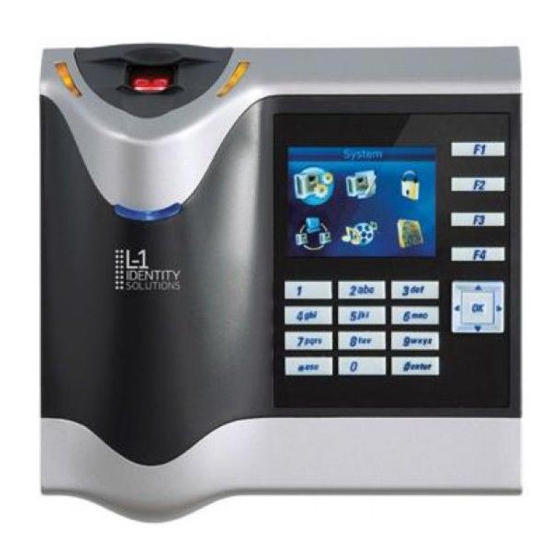
Installation Guide – October 2009 – Edit Purposes Only 2009 NOTICE This symbol denotes a situation needing additional advice to avoid incorrect usage. 1.2 PRODUCT OVERVIEW 1.2.1 V-FLEX 4G Figure 1-1 4G Flex Device October 15 2009 – Installation Guide Draft – Edit Purposes Only Page 2 ... - Page 3 Installation Guide – October 2009 – Edit Purposes Only 2009 1.2.2 V-STATION 4G Figure 1-2 V-Station 4G Device October 15 2009 – Installation Guide Draft – Edit Purposes Only Page 3 ...
- Page 4 Installation Guide – October 2009 – Edit Purposes Only 2009 1.2.3 V-STATION 4G EXTREME DEVICE Figure 1-3 V-Station EXTREME Device October 15 2009 – Installation Guide Draft – Edit Purposes Only Page 4 ...
- Page 5 Installation Guide – October 2009 – Edit Purposes Only 2009 1.2.4 V-STATION 4G PIV/TWIC INDOOR Figure 1-4 V-Station 4G PIV/TWIC Indoor October 15 2009 – Installation Guide Draft – Edit Purposes Only Page 5 ...
- Page 6 Installation Guide – October 2009 – Edit Purposes Only 2009 1.2.5 V-STATION 4G EXTREME PIV/TWIC Figure 1-5 V-Station 4G Extreme PIV/TWIC October 15 2009 – Installation Guide Draft – Edit Purposes Only Page 6 ...
- Page 7 Installation Guide – October 2009 – Edit Purposes Only 2009 1.2.6 SENSORS The V-Station 4G and V-Flex 4G devices offer three types of sensor interfaces. 1.2.6.1 UPEK TCS Figure 1-6 UPEK TCS Sensor Key Features: • Active Capacitive Fingerprint sensing •...
- Page 8 Installation Guide – October 2009 – Edit Purposes Only 2009 1.2.6.3 LUMIDIGM VENUS OPTICAL SENSOR Figure 1-8 Lumidigm Venus Optical Sensor Key Features: • TBD • TBD • TBD October 15 2009 – Installation Guide Draft – Edit Purposes Only Page 8 ...
- Page 9 Installation Guide – October 2009 – Edit Purposes Only 2009 1.2.7 DEVICE DIMENSIONS 1.2.7.1 V-Flex 4G Device Figure 1-9 V-Flex 4G Dimensions October 15 2009 – Installation Guide Draft – Edit Purposes Only Page 9 ...
- Page 10 Installation Guide – October 2009 – Edit Purposes Only 2009 1.2.7.2 V-STATION 4G Figure 1-10 V-Station 4G Dimensions October 15 2009 – Installation Guide Draft – Edit Purposes Only Page 10 ...
- Page 11 Installation Guide – October 2009 – Edit Purposes Only 2009 1.2.7.3 V-STATION EXTREME PIV/TWIC DEVICES 1.2.7.3.1 V-STATION 4G EXTREME Figure 1-11 V-Station 4G Extreme Dimensions October 15 2009 – Installation Guide Draft – Edit Purposes Only Page 11 ...
- Page 12 Installation Guide – October 2009 – Edit Purposes Only 2009 1.2.7.3.2 V-STATION 4G EXTREME WITH ACCESSORIES Figure 1-12 V-Station 4G Extreme with Accessories Dimensions October 15 2009 – Installation Guide Draft – Edit Purposes Only Page 12 ...
- Page 13 Installation Guide – October 2009 – Edit Purposes Only 2009 1.2.7.3.3 V-STATION 4G EXTREME PIV/TWIC Figure 1-13 V-Station 4G Extreme PIV/TWIC October 15 2009 – Installation Guide Draft – Edit Purposes Only Page 13 ...
- Page 14 Installation Guide – October 2009 – Edit Purposes Only 2009 1.2.7.3.4 V-STATION EXTREME PIV/TWIC WITH ACCESSORIES Figure 1-14 V-Station 4G Extreme PIV/TWIC with Accessories Dimensions 1.2.8 SAFETY PRECAUTIONS Below are safety precautions that should be observed when operating or installing a device.
- Page 15 Installation Guide – October 2009 – Edit Purposes Only 2009 1.2.8.1 ELECTRO-STATIC DISCHARGE L-1 Identity Solutions recommends that Administrators inform Users of these points during the enrollment process: Always use the Ridge-Lock to position a finger *before* touching the sensor. Always stand on the ESD-dissipative floor covering (if installed).
- Page 16 Installation Guide – October 2009 – Edit Purposes Only 2009 Do not plug any equipment into the USB port other than flash memory devices. Do not allow users to place or hang objects on the device, such as coffee cups or purses. Do clean the device regularly to remove dust, grime, and fingerprint residue.
-
Page 17: Planning The Installation
Installation Guide – October 2009 – Edit Purposes Only 2009 CHAPTER 2 - PLANNING THE INSTALLATION CHAPTER OVERVIEW This chapter details how to plan a successful installation, recommended steps, and explains the hardware and software components of typical setup scenarios. 2.1 PLANNING THE INSTALLATION Planning the installation is the single most important aspect of a successful installation. - Page 18 If you have any unresolved issues with the items on this list, contact L-1 Identity Solutions Technical Support for additional information before beginning any installation. WARNING V-Station 4G and V-Flex 4G devices should be installed by only a qualified technician. If you are not qualified to perform an installation task, call L-1 Identity Solutions Technical Support or contact a qualified installer 2.1.1 RECOMENDED STEPS FOR A SUCCESSFUL INSTALLATION...
- Page 19 Installation Guide – October 2009 – Edit Purposes Only 2009 2.1.2 REQUIREMENTS PC workstation with: 1 GHz Intel(r) Pentium(r) 4 processor or equivalent 1 GB RAM (2 GB recommended) CD-ROM drive One available COM port or USB port Ethernet card Display: 1024 x 768 high color (minimum) Regulated DC Power supply Door controller...
- Page 20 2.1.2.2.6 ORACLE 10G EXPRESS Hard disk space: Server component: 1.6 GB Client component: 75 MB 2.1.2.3 NETWORK REQUIREMENTS The V-Station 4G and V-Flex 4G devices function on 100 baseT networks. 2.1.2.4 SOFTWARE REQUIREMENTS Both SecureAdmin Server and SecureAdmin Client require these software applications as prerequisites: .net Framework 3.5...
- Page 21 VeriSign. 2.1.3 UNPACK EQUIPMENT Unpack all items and check against the packing list. 2.1.3.1 PARTS LIST 2.1.3.1.1 V-STATION 4G or V-FLEX 4G DEVICES Hardware 1 V-Station 4G or V-Flex 4G device 1 Wall mounting plate/mullion mounting plate 6 #6-32 3/4"...
- Page 22 Installation Guide – October 2009 – Edit Purposes Only 2009 1 Micro-USB device cable 1 Micro-USB PC cable Tools 1 1/8" pin-in-hex security key 2.5 2.1.3.1.2 V-STATION 4G EXTREME DEVICES Hardware 1 V-Station Indoor or Outdoor 4G device 29 Super B-Wire Connectors, Dolphin DC-100-S 2 dielectric grease (maybe 1 is enough, need to try out) 1 Cable, User Wiegand, 4G Outdoor 8 wall mount anchor, conical, for #8 screws...
- Page 23 Reader application is available on the Installation CD or at: http://www.adobe.com 2.1.4 CHOOSING THE INSTALL LOCATION V-Station 4G and V-Flex 4G devices are designed to mount on either a double-gang electrical box or on any flat surface. Consult with local professionals regarding any building and safety codes that might affect your installation.
- Page 24 Installation Guide – October 2009 – Edit Purposes Only 2009 2.1.5 PLAN DEVICE NETWORK The 4G devices feature a built-in single-door relay that allows them to control a single door lock. They can therefore function on their own or as part of a larger access control system.
- Page 25 If your installation requires the use of network communications, then the choice of cable, the cable run length, the network topology, and the termination of the network are important aspects that must be considered. The V-Station 4G and V-Flex 4G devices can be networked using RS-232, RS-485, or Ethernet protocols.
- Page 26 Installation Guide – October 2009 – Edit Purposes Only 2009 Spec RS-485 RS-232 100BaseT Number of Unlimited Devices on one line Maximum Data 56 Kbps 56 Kbps* Auto- Rate (recommended) (recommended) negotiated 2.1.6.1 RS-232 If your system has only one device, or a few devices (each only a short distance away from the SecureAdmin PC) then RS-232 can be used, provided that each device can have a dedicated RS-232 port.
- Page 27 Installation Guide – October 2009 – Edit Purposes Only 2009 Table 2-2 Category 5 Cable Characteristics Specification Recommendation Capacitance (conductor to conductor) <20 pF/ft. Characteristic Impedance 100 - 120 ohms Nominal DC resistance <100 ohms/1000 ft. Wire gauge 24 AWG stranded Conductors/Shielding >2 pair (shielding is recommended) 2.1.6.2.2 RS-485 CABLE LENGTHS...
- Page 28 Installation Guide – October 2009 – Edit Purposes Only 2009 NOTICE The device on the end of the network should be terminated with a 120 ohm resistor Figure 2-3 Network Topologies Star and Daisy Chain Configurations NOTICE A Daisy configuration is recommended over a Star configuration.. 2.1.6.3 ETHERNET If your system is to be configured for use over Ethernet, the wiring will be slightly different.
- Page 29 Always place the device as close as possible to the power supply and always select a wire size appropriate for the load. V-Station 4G devices run on DC power between 12.5 and 24 VDC. Power requirements for all V-Station 4G and V-Flex 4G models are listed below. October 15 2009 – Installation Guide Draft – Edit Purposes Only Page 29 ...
- Page 30 Installation Guide – October 2009 – Edit Purposes Only 2009 Table 2-3 V-Station 4G and V-Flex 4G Power Requirements Power Requirement: 12 watts Input Voltage Range: 12-24.0 VDC Peak Current (12 VDC) Peak Current (24 VDC) 500 mA Table 2-4 V-Station 4G Extreme Power Requirements...
- Page 31 Installation Guide – October 2009 – Edit Purposes Only 2009 CHAPTER 3 - INSTALL SOFTWARE CHAPTER OVERVIEW This chapter shows how to install, repair, modify, upgrade, and uninstall the SecureAdmin Server and Client software packages. 3.1 INSTALL SOFTWARE To install the SecureAdmin software, the user must have Administrator rights. Any software required to install SecureAdmin is detected and installed automatically during the setup process.
- Page 32 Installation Guide – October 2009 – Edit Purposes Only 2009 Figure 3-2 Prerequisites Click Install . Microsoft .NET Framework 3.5 SP1 is installed. Restart the computer when asked. The installation process continues automatically after the computer is restarted. Repeat the same process for Windows Installer 4.5. Figure 3-3 Restart Message October 15 2009 – Installation Guide Draft – Edit Purposes Only ...
- Page 33 Installation Guide – October 2009 – Edit Purposes Only 2009 Figure 3-4 SecureAdmin Server Installation Wizard The Secure Admin Server Installation Wizard is displayed. Click Next to continue the setup process. Figure 3-5 SecureAdmin Server License Agreement The L-1 Identity Solutions License Agreement is displayed. Select the appropriate radio button to agree with the terms and then click the Next button (You must accept the terms of the licence agreement to continue the installation process).
- Page 34 Installation Guide – October 2009 – Edit Purposes Only 2009 Figure 3-6 SecureAdmin Server Choose Destination Location The Choose Destination Location screen is displayed. Accept the default installation folder and click the Next button or click Browse to choose your own installation path. After you specify a destination folder, the Database Selection screen is displayed.
- Page 35 Installation Guide – October 2009 – Edit Purposes Only 2009 Using the radio buttons, select the type of database application you intend to work with, or select an existing database. Click the Next button. If you selected the SQL Server 2008 Express Edition option, it will be installed locally if it is not already installed.
- Page 36 Installation Guide – October 2009 – Edit Purposes Only 2009 You can select existing database instance of SQL Server 2005 or SQL Server 2008 as required from the drop-down of Database server that you are installing to. Select the Database server authentication option and enter valid Login ID and password values.
- Page 37 Installation Guide – October 2009 – Edit Purposes Only 2009 3.1.1.1 REPAIRING AN INSTALLATION OF SECUREADMIN SERVER To repair an installation: 1. Login as Administrator and go to the Install. Double-click the Setup.exe installer file to start the installer. On the L1 Identity Solutions screen, select the Server Installation option. On the SecureAdmin Welcome screen, select the Repair option.
- Page 38 Installation Guide – October 2009 – Edit Purposes Only 2009 1. When you run the setup of SecureAdmin server, it checks to see if previous version of SecureAdmin server is already installed on the machine. If yes, it prompts to upgrade SecureAdmin server.
- Page 39 Installation Guide – October 2009 – Edit Purposes Only 2009 3.1.2 SECUREADMIN CLIENT To install the SecureAdmin client software, follow these steps: 1. Insert the CD into the optical drive. If Autoplay is enabled, the installation process will start automatically. A menu is displayed. If Autoplay is not enabled, start the installation process manually by doubleclicking the Setup.exe file located in the SecureAdmin folder on the CD.
- Page 40 Installation Guide – October 2009 – Edit Purposes Only 2009 Figure 3-14 InstallShield Wizard Figure 3-15 Welcome Screen Click the Next button to continue. The License Agreement screen is displayed. Figure 3-16 SecureAdmin Client License Agreement October 15 2009 – Installation Guide Draft – Edit Purposes Only Page 40 ...
- Page 41 Installation Guide – October 2009 – Edit Purposes Only 2009 The L-1 Identity Solutions License Agreement is displayed. Select the appropriate radio button to agree with the terms and then click the Next button. The Choose Destination Location screen is displayed. Figure 3-17 SecureAdmin Client Choose Destination Location Accept the default installation folder and click the Next button or click Browse to choose your own installation path.
- Page 42 Installation Guide – October 2009 – Edit Purposes Only 2009 Click the Next button. The InstallShield Wizard completes the installation and displays a Finished screen. Select either or both of the optional Check Create Desktop Icon and Launch Secure Admin Client check boxes. Figure 3-19 InstallShield Wizard Finished Click the Finish button.
- Page 43 Installation Guide – October 2009 – Edit Purposes Only 2009 Double-click the Setup.exe installer file to start the installer. On the L1 Identity Solutions screen, select the Client Installation option. On the SecureAdmin Welcome screen, select the Repair option. Click Next to continue. On the Maintenance Complete screen, click the Finish button to complete the repair installation process.
- Page 44 V-Station 4G the hole is to the right. Cut out the square hole with a jigsaw or drywall saw. If the V-Flex 4G device is to be recess-mounted, cut out a hole in the drywall to accommodate the rear extension on the device housing.
- Page 45 To install the mounting plate on to an electrical box, screw the mounting plate to the box with the provided 6-32 screws. CAUTION When installing a recess-mounted V-Flex 4G device, be careful not to damage the tamper switch, as careless handling can shear it off. Figure 4-1 V-Flex 4G Flush-mount Mounting Plate Figure 4-2 V-Flex 4G Recessed-mount Mounting Plate October 15 2009 – Installation Guide Draft – Edit Purposes Only ...
- Page 46 Installation Guide – October 2009 – Edit Purposes Only 2009 Figure 4-3 V-Station 4G Mounting Plate NOTICE The V-Station 4G device can only be flush mounted. October 15 2009 – Installation Guide Draft – Edit Purposes Only Page 46 ...
- Page 47 Installation Guide – October 2009 – Edit Purposes Only 2009 Figure 4-4 V-Station 4G Extreme Mounting Plate October 15 2009 – Installation Guide Draft – Edit Purposes Only Page 47 ...
- Page 48 6 #4-8 1" nylon wall anchors The hardware shown above is provided to mount the mounting plate to the wall and the V- Station 4G or V-Flex 4G device to the mounting plate. 4.1.3.2 4G Extreme Devices 1 Stainless Steel, Wall Mount Plate 8 wall mount anchor, conical, for #8 screws 6 6-32 Security Screw 1/8"...
- Page 49 Once all the electrical connections have been made to the device, it can be attached to the mounting plate as follows: For the V-Flex 4G, insert the four hooked protrusions on the rear of the device into the corresponding slots on the mounting plate. Hold the device against the plate and gently press it in a downward direction to engage the hooks.
- Page 50 DC power sources, or through a Power Over Ethernet (PoE) injector for V-Station 4G and V-Flex 4G. The two options for providing 1 2V power to V-Station 4G and V-Flex 4G devices are by using an external wall plug-in adapter (Figure 4-7), or through external wiring and a mini plug (Figure 4-8).
- Page 51 Installation Guide – October 2009 – Edit Purposes Only 2009 The V-Station 4G, V-Flex 4G devices both support Power over Ethernet (PoE), using their RJ-45 Ethernet interface. When these devices are to be powered over Ethernet, an IEEE 802.3af compliant Active Midspan Injector must be used. Such an injector is not supplied with L-1 Identity Solutions products.
- Page 52 RJ-45 connector. Figure 4-12 RJ45 Pin Location 4.1.6 CONNECT DEVICE TO NETWORK The V-Station 4G and V-Flex 4G devices support both RS-232/RS-485 and Ethernet 1 0baseT and 1 00baseTX network protocols. 4.1.6.1 ETHERNET NETWORK CONNECTIONS Ethernet connections to the device are made through a standard RJ-45 connector on the back of the device.
- Page 53 Installation Guide – October 2009 – Edit Purposes Only 2009 When connecting the device to the network, the following procedures must be followed: Use Category 5 cabling with a characteristic impedance of 120 ohms for RS-485 networks. Category 5 cables with a characteristic impedance of 100 ohms can also be used, but with lower performance.
- Page 54 NOTICE The maximum recommended distance from an access point is 25 feet. 4.1.7 SINGLE-DOOR CONTROLLER INSTALLATION The V-Station 4G and V-Flex 4G devices incorporate an internal relay that enables them to operate a deadbolt/door strike directly. October 15 2009 – Installation Guide Draft – Edit Purposes Only Page 54 ...
- Page 55 170 mA capacity of the V-Station 4G or V-Flex 4G device's internal relay.
- Page 56 V-Station 4G or V-Flex 4G device's internal relay maximum voltage rating of 250 volts. The external relay should be connected. Note that snubber diodes (1 N2007 or equivalent) should be connected across the external relay coil and the deadbolt/door strike.
- Page 57 Installation Guide – October 2009 – Edit Purposes Only 2009 4.1.8 AUX PORT The Aux port is a USB 2.0 auto-negotiate connector located on the bottom of the device. To access the Aux port, the Aux port door must first be removed. Use the provided pin-in-hex security key to remove the #6-32 security screw retaining the plastic Aux port door.
- Page 58 Figure 4-16 USB Memory Key 4.1.9 INSTALL FERRITE CORE In order for the V-Station 4G and V-Flex 4G devices to comply with FCC Class B & CISPR 22 Class B regulations, the installer and/or end user is required to use the supplied Ferrite Material on the Ethernet, DC, and all I/O cables exiting the rear of the device.
- Page 59 Installation Guide – October 2009 – Edit Purposes Only 2009 Ethernet Ferrite P/N: STEWARD 28A2432-0A2 DC & I/O Lines P/N: STEWARD 28A4155-0A2 Install the ferrite cores as close to the device as possible. Figure 4-18 Installation of Ferrite Cores October 15 2009 – Installation Guide Draft – Edit Purposes Only Page 59 ...
- Page 60 Installation Guide – October 2009 – Edit Purposes Only 2009 CHAPTER 5 - SYSTEM START-UP PROCEDURES CHAPTER OVERVIEW This chapter explains the various start-up procedures and checks that should be performed before applying power to a device. Chapter Index 5.1 SYSTEM START-UP PROCEDURES To avoid the need for difficult troubleshooting, system start-up must follow this step-by- step procedure.
- Page 61 1 volt across the resistor. 5.1.3 DEVICE GROUND FAULT CHECK To check for a ground fault on a new V-Station 4G or V-Flex 4G device: 4. Apply power to all devices already successfully connected to the RS-485 line. Power up the new device but do not connect it to the RS-485 line.
- Page 62 Installation Guide – October 2009 – Edit Purposes Only 2009 6.1 CONFIGURE DEVICE V-Station 4G and V-Flex 4G devices must be configured before use. This includes setting various communication parameters and calibrating the device's sensor 6.1.1 REGISTER DEVICE After a device is physically installed, it must registered. This can be done several ways -...
- Page 63 Installation Guide – October 2009 – Edit Purposes Only 2009 Figure 6-2 Register via Server Dialog Box Select the Search Automatically check box (UDP protocol must be enabled on the net-work. Click the Scan button. SecureAdmin scans the network for connected devices and lists the results.
- Page 64 Installation Guide – October 2009 – Edit Purposes Only 2009 Enter a Device Name. Select a Group. Click Register. A Device Summary is displayed. Figure 6-4 Device Summary Dialog Box Click OK. Click Close. The device is registered. 6.1.1.2 TO REGISTER A DEVICE VIA A CLIENT 5.
- Page 65 Enter the network IP Address of the device you want to connect to. NOTICE The first time a V-Station 4G or V-Flex 4G device is connected to the computer via the USB/RS-232 interface, the Windows Found New Hardware Wizard might start. As all required device drivers are installed when Secu-reAdmin is installed, simply follow the prompts, accepting the default choices when possible, to install the device.
- Page 66 Installation Guide – October 2009 – Edit Purposes Only 2009 Click Next. The Step 3 Server Communication Parameter dialog box is displayed. Figure 6-7 Step 3 Server Communication Parameter Dialog Box Select the radio button that corresponds how the server will connect to the device, either by Serial Port or by Ethernet.
- Page 67 Installation Guide – October 2009 – Edit Purposes Only 2009 Figure 6-8 Step 4 Register Device Dialog Box Enter a Device Name. Select the Group the device will belong to from the drop-down menu. Click Register. The Device Summary dialog box is displayed. Figure 6-9 Device Summary Dialog Box October 15 2009 – Installation Guide Draft – Edit Purposes Only ...
-
Page 68: Maintenance And Cleaning
7.1 MAINTENANCE AND CLEANING The V-Station 4G and V-Flex 4G devices require very little in the way of daily maintenance except for occasional cleaning and disinfecting. The V-Station 4G and V- Flex 4G devices feature field-replaceable sensors. - Page 69 Installation Guide – October 2009 – Edit Purposes Only 2009 With the wall mounting plate mounted and the device secured to the mounting plate, the tamper switch is depressed, closing the electrical circuit. When the device is removed from the wall by removing the security screws or in the event that the device is removed from the wall by force, the tamper switch opens.
- Page 70 7.1.1.2.1 V-FLEX 4G To replace the sensor module in a V-Flex 4G device, follow these steps: 6. Remove the security screw and slide the V-Flex 4G device up until the hooks are free from the wall-mounting plate. Remove two Philips screws.
- Page 71 Installation Guide – October 2009 – Edit Purposes Only 2009 Figure 7-3 Non-Removable Parts (V-Flex 4G) 7.1.1.2.2 V-STATION 4G To replace the sensor module in a V-Station 4G device, follow these steps: 7. Remove the security screw. Tilt the device at an angle approximately 90 degrees to the wall.
- Page 72 Installation Guide – October 2009 – Edit Purposes Only 2009 Disconnect the sensor module wiring harness from the internal device connector. It might be necessary to rock the connector back and forth to work it out. Do not pull with excessive force as you might damage the mating connector. Disconnect the sensor module wiring harness from the sensor module.
- Page 73 Installation Guide – October 2009 – Edit Purposes Only 2009 Figure 7-6 Calibration Wizard Step 1 of 2 Dialog Box Select the device you want to calibrate in the Current Device menu. Click Calibrate. Wait as the device sensor is calibrated. Click Next.
- Page 74 To clean the fingerprint sensor in a V-Station 4G or V-Flex 4G device: 9. Remove the electrical power from the device. Moisten (do not saturate) a clean cotton swab or a lint-free cloth with rubbing (Isopropyl) alcohol.
- Page 75 Installation Guide – October 2009 – Edit Purposes Only 2009 WARNING Never use products such as abrasive cleaning powders, steel wool, scouring pads, or fine sandpaper to clean the sensor surface. These types of cleaning products will damage the sensor surface. Rub the sensor surface with the moistened cotton swab or lint-free cloth.
-
Page 76: Troubleshooting
Installation Guide – October 2009 – Edit Purposes Only 2009 CHAPTER 8 - TROUBLESHOOTING CHAPTER OVERVIEW This chapter information about any error messages that might be experienced during the installation process. 8.1 TROUBLESHOOTING 8.1.1 INSTALLATION ERROR MESSAGES These error messages might occur during the SecureAdmin installation process. 8.1.1.1 ERROR 1406 - INSUFFICIENT PRIVILEGES Figure 8-1 Error 1406 This error can occur during SecureAdmin Client installation at the last step (right before... - Page 77 Installation Guide – October 2009 – Edit Purposes Only 2009 Log off and log on either as a Administrator or another user that has sufficient privileges to install software and perform the setup process again. 8.1.1.2 ERROR 27552 - ERROR CREATING DATABASE Figure 8-2 Error 27552 This error can occur during SecureAdmin Server installation process.
- Page 78 Installation Guide – October 2009 – Edit Purposes Only 2009 This error can occur during SecureAdmin Server installation process on the User configuration screen (after the database configuration screen). If it occurs, it means that the password provided is not strong enough. Click OK, and re-enter a password that is considered more secure.
- Page 79 Installation Guide – October 2009 – Edit Purposes Only 2009 8.1.1.4 ERROR 27502 - USER NOT ASSOCIATED WITH TRUSTED SQL SERVER Figure 8-4 Error 27502 - User Not Associated This error can occur during the SecureAdmin Server installation process. If it occurs, it means that the InstallShield Wizard could not access the specified SQL database.
- Page 80 Installation Guide – October 2009 – Edit Purposes Only 2009 8.1.1.5 ERROR 27502 - SQL SERVER DOES NOT EXIST Figure 8-5 Error 27502 - Server Does Not Exist This error can occur during the SecureAdmin Server installation process (at the time of database configuration, after the database selection screen).
- Page 81 Installation Guide – October 2009 – Edit Purposes Only 2009 8.1.1.6 INSUFFICIENT SYSTEM MEMORY Figure 8-6 Insufficient System Memory This error can occur during the SecureAdmin Server installation process at the first screen after selecting server installation from the options screen. If it occurs, it means that the computer you are trying to install SecureAdmin Server on does not have sufficient system memory.
- Page 82 Installation Guide – October 2009 – Edit Purposes Only 2009 This error can occur during the SecureAdmin Client installation process when Secu-reAdmin starts to configure components, after the fingerprint feedback options selection. October 15 2009 – Installation Guide Draft – Edit Purposes Only Page 82 ...
- Page 83 Installation Guide – October 2009 – Edit Purposes Only 2009 9.1 CHAPTER 9 - NOTICES The 4G lines of products have been tested for compliance with all applicable international standards. The resulting approvals are listed below, and are additionally printed on the labelling located on the rear panel of the product. V- Flex 4G FCC, CE V- Station 4G...
- Page 84 (8inch) spacing between the unit and all person’s body (excluding hands and feet) during wireless modes of operation. 9.1.2 CE Information to Users All Veri-Series 4G devices have the CE mark, for compliance with CISPR22/EN55022 requirements. For European Union (EU) countries, V-Flex 4G and V- Station 4G are October 15 2009 – Installation Guide Draft – Edit Purposes Only Page 84 ...
- Page 85 Installation Guide – October 2009 – Edit Purposes Only 2009 compliant with CE under the R&TTE Directive, related to the radio transceivers that are part of their design. 9.1.3 Warning to Users CAUTION Changes or modifications not expressly approved by L-1 Identity Solutions Inc.
Need help?
Do you have a question about the V-Flex 4G and is the answer not in the manual?
Questions and answers