Table of Contents
Advertisement
Quick Links
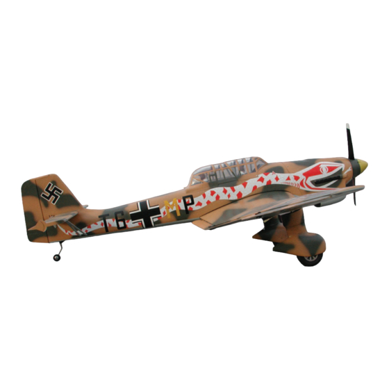
Universally known as perhaps the most effective
dive bomber ever flown, the Stuka (a contraction
of the word "Sturzkampfflugzeug" or diving battle
aircraft) was born of a generation of aircraft ren-
dered obsolete before the advent of WWII.
Design work began in 1933, and the prototype
first flew in 1935. Tested in combat first in the
Spanish Civil War, the Stuka proved its worth.
The -B model grew out of shortcomings defined
in this conflict, and cemented the profile of the
Stuka that would terrorize a continent only a few
years later. The Stuka flew in all theaters in
WWII, enjoying great success in the early battles
in Poland Scandinavia, and Russia. Only the
Battle of Britain would humble the mighty Stuka,
showing that it couldn't succeed against deter-
mined fighter opposition.
The Stuka has a wingspan of 45 feet 3 inches, a
length of 36 feet 3 inches, a maximum weight of
almost 9,500 pounds, and could carry a variety
of bombs to a maximum of 2,200 pounds. The
Stuka is powered by a water-cooled, 12 cylinder
iverted-vee Junkers Jumo 211engine producing
1,200 horsepower. Crew consisted of the pilot
and a gunner firing a 7.92 mm MG 15 machine
gun. Forward firepower included two 7.92 mm
MG 17 machine guns mounted in the wings.
Later models were outfitted as tank destroyers,
firing 40 mm cannons mounted in pods under
the wings.
Skyshark R/C Corporation
75 Mid Cape Terrace, Ste 7
Cape Coral, FL 33991, U.S.A.
Website: www.skysharkrc.com
email: cservice@skysharkrc.com
Advertisement
Table of Contents

Related Manuals for Skyshark Stuka


Summary of Contents for Skyshark Stuka
- Page 1 Skyshark R/C Corporation The Stuka has a wingspan of 45 feet 3 inches, a 75 Mid Cape Terrace, Ste 7 length of 36 feet 3 inches, a maximum weight of Cape Coral, FL 33991, U.S.A.
-
Page 2: Engine Options
Below 3500 feet in elevation, a good .45 will fly the Stuka with authority. Above 3500 feet, a larger engine will help return the airplane to sea level perform- Your airplane has many unique features ance. - Page 3 Accessories needed to finish the Stuka: Sullivan Gold-N-Rods, 48" (Part no. 504) or other appro- The Stuka can be built by a person with average building priate pushrods skills. It is designed for someone who has built a trainer or low wing sport plane.
-
Page 4: Horizontal Stabilizer Assembly
Horizontal Stabilizer Assembly 3. Sheet both sides of the vertical stab. So not sheet the tab on S2. 1. Pin S1 to the board. Cut the stab leading edge from 4. Sand the leading edge to shape. Sand all the edges 3/8 x ¼... -
Page 5: Rudder Assembly
Rudder Assembly Center Wing Section 1. Epoxy W2A to W2. Make a right and left side (be careful here; it’s easy to make two left sides!) 1. Glue R2 into the slot in R1. Repeat for R3, R4, R5, and R6. 2. - Page 6 6. Slide W22 Ply Servo Tray into the slots in W1 and W2. Slide W3s in place and pin to the board. 13. Unpin the assembly from the board and turn it over. Cut the bottom balsa spars from ¼ x ¼ stock and 7.
- Page 7 19. Glue W21 Dowel Guides to the top and bottom spars as indicated on the plans. Install so that the arrow faces up and inward. This will properly align the hole for the dowel. 20. Slide F23 onto W1. This will provide a guide for drilling the holes in the leading edge for the dowels.
-
Page 8: Right Wing Panel Assembly
33. Cut slots in W1 and W2s for locating W23 Ply Holddown Plate. The location for W23 is shown on the plans. Glue W23 in place. Drill a small pilot hole 37. Add 1/8 x ¼ spacers to W2 to support the bottom through W23, W1 and the top sheeting to locate the center sheeting, just as you did with the top. - Page 9 12. Select two 1/16” x 4” x 24” sheets. Cut a 1/16 x 3 x 36 balsa sheet in half. Edge glue the two 4” sheets and one 3” sheet to form the top sheeting. 3. Thin the outer 4” of the balsa spar to allow the fit of the last two ribs.
-
Page 10: Left Wing Panel Assembly
19. Trim the trailing edge to match the top sheeting and the center section sheeting. 20. Glue on the wingtip. Sand to shape. Note: the slots in the trailing edge in the picture will be cut later. 6. Drill a hole in W20 and assemble the bellcrank to it. Left Wing Panel Assembly 7. -
Page 11: Fuselage Assembly
Fuselage Assembly 14. Mark a point 9/16” perpendicular to W17 at W8. Mark another point 11/16” perpendicular to W18 at 1. Pin two ¼ x ¼ x 36 balsa spars to the fuselage top W12. Connect these points and the trailing edge of view as shown. - Page 12 16. Add the pushrods by feeding the housings through 11. Add a stringer between F3A and F5A, fitting in the the holes in the bulkheads. A slight amount of the slot in F4A. This stringer is for locating the sheeting stringer near F9A will have to be relieved to allow only.
- Page 13 30. Align the trailing edge of the wing with the fuselage and mark it’s location. Drill a hole through the wing center section (corresponding with the pilot hole you drilled earlier) and through F24. Tap the hole in F24 for your wing holddown bolt. Remove the wing from the fuselage.
- Page 14 40. Using the elevator assemblies as a guide, glue the stab horns onto the ends of the horizontal stabiliz- 41. Fill the aft fuselage area with lightweight filler to fill any gaps and smooth the surfaces. 48. Cut an access hole in the belly pan for servo access.
- Page 15 4. The hinges will set at an angle, so carefully, using a 13. Same hinge assembly techniques, glue two FHs 1/16” drill bit, drill the hole in the hinges to an angle together, and make two hinges. Cut the 1/16” wire (it helps to hand drill this).
-
Page 16: Final Assembly
25. Locate the position of the maple blocks either side of W4. Mount the control horns on each flap section and gauge the angle to the block. Drill the block at that angle, and install pushrods into the blocks. Connect with clevises to the control horns. We will adjust them in a moment. -
Page 17: Engine Installation
Flying builder’s choice, and individual tastes, styles, and compo- The Stuka is a very stable flyer, but approach the first few nent selection, so any detailed descriptions would be flights with caution; it will take several flights to “dial in” the impossible. - Page 20 Skyshark R/C Gauge Face Assembly Instructions Paper gauge faces are located on the 3-view drawing that are included with the instruction manual. 3. Color any necessary parts of the paper gauge panel and apply glue to the front of the paper.
Need help?
Do you have a question about the Stuka and is the answer not in the manual?
Questions and answers