Table of Contents
Advertisement
Quick Links
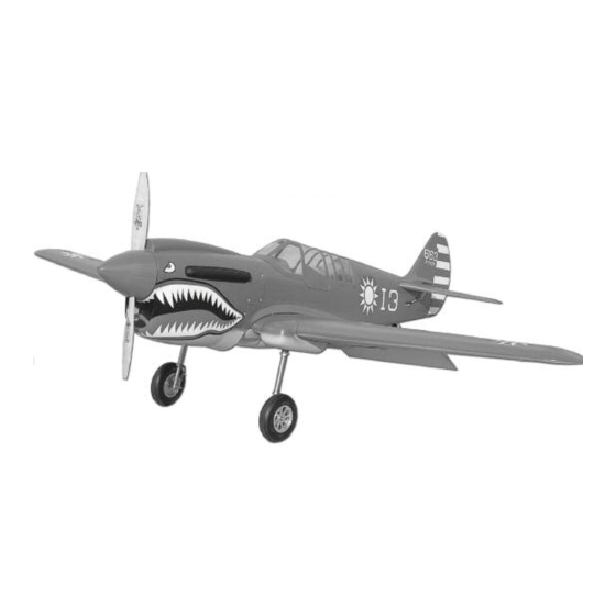
Features:
• Heavy duty fiberglass fuselage with molded panel lines
• Balsa and ply wing covered and painted
• Pin hinges for all control surfaces
• Hand Painted fiberglass cowl
• Quality USA made 4-40 hardware included
• Extra-heavy duty fiberglass accessories
• Designed for retracts on main and tail
• Instrument panel kit
• 5-1/2" Machined aluminum spinner
• Quick-Align engine mounting system
Specifications:
Wingspan:........ 82 inches
Length:............. 71 inches
Wing Area:....... 1190 Sq. in.
Weight:............. 19 - 23 lbs
Skyshark R/
orporation
Engine:............ 45 - 65cc gasoline
Radio:.............. 6 channel minimum
1924 N. Pima Drive • Lake Havasu City, Z 86403, U.S. .
Scale: .............. 1/5.5
Phone: (928) 854-6100 • Toll Free: 1-866-854-6100
Fax:(928) 854-6111
Website: www.skysharkrc.com
email: custserv@skysharkrc.com
Advertisement
Table of Contents

Subscribe to Our Youtube Channel
Related Manuals for Skyshark P-40N


Summary of Contents for Skyshark P-40N
- Page 1 Wingspan:..82 inches Length:..... 71 inches Wing Area:..1190 Sq. in. Weight:..... 19 - 23 lbs Skyshark R/ orporation Engine:.... 45 - 65cc gasoline Radio:....6 channel minimum 1924 N. Pima Drive • Lake Havasu City, Z 86403, U.S. .
- Page 2 Occasionally hints will be included at certain building steps. These are not required for completion, rather they The Skyshark P-40N is painted with fuel proof 2-part paint. are tips intended to ease a particular process. We have tested it using 25% nitro and standard gasoline. If...
- Page 3 Use as little rudder as possible to keep the airplane flying straight. The wing is designed to help reduce tip stalls at lower speeds. Due to this, the Skyshark P-40 can be land- ed a little slower than most other P-40s in this size range.
- Page 4 5. Remove the flaps and place a drop of oil on the joint of each Sierra Giant Scale P112 aluminum servo mounts. These are avail- hinge. This will keep the epoxy from getting into the hinge joint when able from Skyshark or Sierra Giant Scale. they are glued in place.
- Page 5 8. Install the aileron hinges using the same method as the flaps. 6. Insert the hinges into the flap and trailing edge of the wing. Check Note: The hinge joint will be inset in the aileron leading edge in order for proper alignment and operation of the flap.
- Page 6 Before fastening the servo hatches in place, it’s a good idea to make sure the servos are properly centered and the arms are in the correct position for maximum control movement. 10. Use a 1/16” drill bit to drill holes in the servo hatch and mounting plate as shown.
-
Page 7: Wing Joining
Wing Joining 19. pply a light coat of 30 min epoxy to one half of the wing tube and slide into one wing half. pply epoxy to the other end of the tub 17. Fit the aluminum tube in the wings and assemble the wing halves and to both root ribs. - Page 8 26. Place the wing on the fuselage and double check the wing dowel 23. Cut off the sides of the template at the molded lines. alignment. Once everything is aligned, drill two 1/4” holes in the fuselage wing dowel plate at the marked locations. 24.
- Page 9 29. Drill a ¼" hole through the wing and wing mounting plate at the marks made in the previous step. Insure the drill is straight and the wing is aligned and held securely in place. 30. Enlarge the fuselage wing mounting plate holes to 19/64" and install the 1/4-20 metal blind nuts securely on the back side using C 32.
-
Page 10: Tail Surfaces
36. pply 5 or 30 minute epoxy to each mounting edge and fit the belly pan to the wing. pply weight to the belly pan until the epoxy has cured. We use socks filled with lead shot for this task but maga- zines or plastic bags filled with sand also work. - Page 11 40. Remove the stab and carefully cut the covering about 1/16" inside of the lines you just made. Remove the covering. Be careful not to cut into the balsa sheeting 44. When the epoxy cures completely, remove the masking tape and inspect the stab to insure it is well glued.
- Page 12 49. Use a pencil to mark the centerline on the sides of the engine mount. The centerline will be in line with the cross section on the back of the mount. 47. Hinge the elevators to the H stab using the same method as was used with the ailerons.
- Page 13 57. ttach the spinner backplate and prop to the engine and align 54. Install the motor and mount onto the firewall. Note: you may the backplate with the front of the cowl. There should be a 1/8" gap between the spinner backplate and the front of the cowl. Note: You need to drill out the mount bolt holes to 15/16"...
- Page 14 66. Use medium C to tack the back of the engine box in place. 62. Use 5 min epoxy to attach a hardwood block to each hole loca- tion inside the fuselage. These will act as the screw backup when you attach the cowl.
-
Page 15: Elevator And Rudder Servo Installation
68. Once the epoxy has cured, you can install the muffler, ignition, throttle servo and fuel tank/fill setup. You may need to sand a little off the firewall box in order to fit the muffler. The throttle servo can either be installed on the firewall box or inside the fuselage on the servo tray. - Page 16 77. Re-install the control arms on the servos and connect the clevis- es to the control horns. djust the length as necessary by threading the rod in or out of the plastic swivel link arm or clevis. Tighten the lock nuts and use thread locking compound to secure them in place. 78.
- Page 17 Retractable Tail Gear 85. Measure 1-5/8" up from the bottom of the rudder and install a 1- 1/8" control horn using the same method as the elevator horns. 91. lign the tailwheel retract as shown. It should sit back at least 3/16"...
- Page 18 99. Carefully cut the abs wheel well covers along the scribed lines and fit in place as shown. You will also need to drill holes in the cover so the airlines on the end of the cylinder can be routed into the wing. Note: You may need to cut slots in the ribs so you have room to fit the servo wires with the wheel well cover in place.
- Page 19 108. Use medium C or 5 min epoxy to glue the clear lens piece to the back of the black panel. 109. Use medium C to glue the paper gauge face to the clear lens piece. Make sure the gauges are aligned correctly. Note: Only use a 103.
-
Page 20: Decal Placement
Control Throws Aileron 3/4” up and down Elevator 1-1/2” up 1” down Rudder 1-1/2” left and right Flaps 2” down Preflight checks • Double check that all control surfaces are properly glued by pulling on them firmly. 116. Carefully cut the exhaust stacks along the outside of the mold- •...
Need help?
Do you have a question about the P-40N and is the answer not in the manual?
Questions and answers