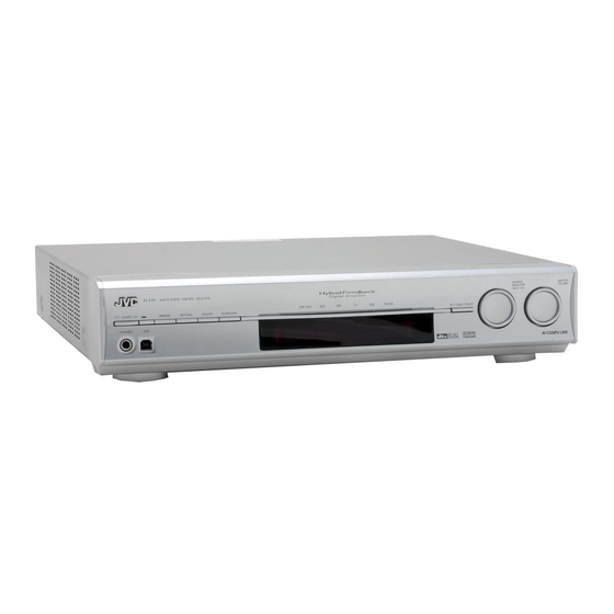
JVC RX-D201S Service Manual
Audio/video control receiver
Hide thumbs
Also See for RX-D201S:
- Instructions manual (87 pages) ,
- Service manual (63 pages) ,
- Instructions manual (47 pages)
Table of Contents
Advertisement
Quick Links
SERVICE MANUAL
AUDIO/VIDEO CONTROL RECEIVER
5
2005
MB364
RX-D201S,RX-D202B
Lead free solder used in the board (material : Sn-Ag-Cu, melting point : 219 Centigrade)
1
PRECAUTION. . . . . . . . . . . . . . . . . . . . . . . . . . . . . . . . . . . . . . . . . . . . . . . . . . . . . . . . . . . . . . . . . . . . . . . . . 1-3
2
SPECIFIC SERVICE INSTRUCTIONS . . . . . . . . . . . . . . . . . . . . . . . . . . . . . . . . . . . . . . . . . . . . . . . . . . . . . . 1-6
3
DISASSEMBLY . . . . . . . . . . . . . . . . . . . . . . . . . . . . . . . . . . . . . . . . . . . . . . . . . . . . . . . . . . . . . . . . . . . . . . . 1-7
4
ADJUSTMENT . . . . . . . . . . . . . . . . . . . . . . . . . . . . . . . . . . . . . . . . . . . . . . . . . . . . . . . . . . . . . . . . . . . . . . . 1-19
5
TROUBLESHOOTING . . . . . . . . . . . . . . . . . . . . . . . . . . . . . . . . . . . . . . . . . . . . . . . . . . . . . . . . . . . . . . . . . 1-19
TABLE OF CONTENTS
COPYRIGHT © 2005 Victor Company of Japan, Limited
RX-D201S
Area suffix
J ---------------------------- U.S.A.
RX-D202B
Area suffix
J ---------------------------- U.S.A.
C ------------------------- Canada
No.MB364
2005/5
Advertisement
Table of Contents

Related Manuals for JVC RX-D201S


Summary of Contents for JVC RX-D201S
-
Page 1: Table Of Contents
SERVICE MANUAL AUDIO/VIDEO CONTROL RECEIVER MB364 2005 RX-D201S,RX-D202B RX-D201S Area suffix J ---------------------------- U.S.A. RX-D202B Area suffix J ---------------------------- U.S.A. C ------------------------- Canada Lead free solder used in the board (material : Sn-Ag-Cu, melting point : 219 Centigrade) TABLE OF CONTENTS PRECAUTION. - Page 2 SPECIFICATION Amplifier Ω Output Power At stereo operation Front channels 100 W per channel, min. RMS, driven into 6 at 40 Hz to 20 kHz with no more than 0.8% total harmonic distor- tion. Ω At surround operation Front channels 100 W per channel, min.
-
Page 3: Precaution
SECTION 1 PRECAUTION Safety Precautions (1) This design of this product contains special hardware and voltmeter. many circuits and components specially for safety purpos- Move the resistor connection to each exposed metal es. For continued protection, no changes should be made part, particularly any exposed metal part having a return to the original design unless authorized in writing by the path to the chassis, and measure the AC voltage across... - Page 4 Importance administering point on the safety Primary board (Forward side) Main amplifier board (Forward side) F102 F101 Caution: For continued protection against risk of fire, replace only with same type 2 A/125 V for F101, 2 A/125 V for F102, 6.3 A/125 V for F103. This symbol specifies type of fast operating fuse.
- Page 5 Caution after repairs There are two power supply as the second power supply of the transformer. One is a power supply for power IC(3pin), and another is a power supply for the control(5pin). +B for power IC +B for control section (3pins) (5pins) There are two power supply as the second power supply of the transformer.
-
Page 6: Specific Service Instructions
SECTION 2 SPECIFIC SERVICE INSTRUCTIONS This service manual does not describe SPECIFIC SERVICE INSTRUCTIONS. 1-6 (No.MB364) -
Page 7: Disassembly
SECTION 3 DISASSEMBLY Main body section 3.1.1 Removing the top cover (See Figs.1 and 2) (1) From the both sides of the main body, remove the four screws A attaching the top cover. (See Fig.1) Top cover (2) From the back side of the main body, remove the six screws B attaching the top cover. - Page 8 3.1.2 Removing the front panel assembly (See Figs.3 and 4) • Remove the top cover. (1) From the top side of the main body, remove the tie bands Front panel assembly bundling the wires. (See Fig.3.) Reference: OSD connect 2 board After reassembling, bundle the wires with the new tie Main amplifier board bands as before.
- Page 9 3.1.3 Removing the rear panel (See Fig.5) • Remove the top cover. (1) From the back side of the main body, remove the strain re- Strain relief lief from the rear panel in the direction of the arrow and re- Rear panel move the power cord.
- Page 10 3.1.7 Removing the DSP board (See Fig.7) • Remove the top cover. (1) From the back side of the main body, remove the three Wire holder board screws K attaching the DSP board to the rear panel. (2) Remove the screw M attaching the DSP board. (3) From the top side of the main body, remove the two screws N attaching the wire holder board and move the wire holder board with the wires in the direction of the arrow.
- Page 11 3.1.9 Removing the power transformer (See Fig.9) • Remove the top cover. (1) From the top side of the main body, remove the tie bands bundling the wires. Trans primary Reference: board After reassembling, bundle the wires with the new tie Wire holder bands as before.
-
Page 12: No.mb364)1
3.1.12 Removing the DCDC control board (See Fig.10) • Remove the top cover. From the top side of the main body, disconnect the DCDC control board from the main amplifier board in an upward direction while DCDC control board releasing the claw g of the connector CN152 on the main ampli- fier board. - Page 13 3.1.15 Removing the fan motor (See Fig.12.) • Remove the top cover. (1) From the top side of the main body, remove the tie band Main amplifier board bundling the wires. CN103 Reference: After reassembling, bundle the wires with a new tie band as before.
- Page 14 3.1.17 Removing the DSP connect board (See Fig.14) • Remove the top cover, rear panel, tuner, compulink board and DSP board. CN530 Disconnect the DSP connect board from the input board in an up- OSD connect 1 board Tie band CN540 ward direction while releasing the claw k of the connector CN502...
- Page 15 3.1.20 Removing the master clock board (See Fig.16) • Remove the top cover, tuner, DSP board, PWM modulation 1 board, PWM modulation 2 board and OSD connect 1 board. Heat sink (1) Remove the two screws U with a short driver and remove Transistor hold the transistor hold from the joints n of the heat sink.
- Page 16 3.1.21 Removing the main amplifier board (See Figs.17 and 18) • Remove the top cover, tuner, DSP board, DCDC control board, PWM modulation 1 board, PWM modulation 2 board, OSD Main amplifier board CN106 connect 1 board and master clock board. (1) Disconnect the wire from the connector CN261 on the...
- Page 17 3.1.22 Removing the regulator board (See Fig.19) • Remove the top cover, tuner, DSP board, DCDC control board, PWM modulation 1 board, PWM modulation 2 board, OSD Main amplifier board connect 1 board, master clock board and main amplifier board. Regulator board (1) From the forward side of the main amplifier board, discon- nect the wire from the connector CN105.
- Page 18 Front panel assembly section • Remove the front panel assembly. (See "3.1.2 Removing the front panel assembly".) 3.2.1 Removing the JOG board (See Figs.1 and 2) (1) From the inside of the front panel assembly, remove the four screws A attaching the JOG board. (See Fig.1.) Front panel assembly (2) Take out the JOG board while lifting it from the front panel CN913...
-
Page 19: Adjustment
SECTION 4 ADJUSTMENT This service manual does not describe ADJUSTMENT. SECTION 5 TROUBLESHOOTING This service manual does not describe TROUBLESHOOTING. (No.MB364)1-19... - Page 20 Victor Company of Japan, Limited AV & MULTIMEDIA COMPANY AUDIO/VIDEO SYSTEMS CATEGORY 10-1,1chome,Ohwatari-machi,Maebashi-city,371-8543,Japan (No.MB364) Printed in Japan...
- Page 21 SCHEMATIC DIAGRAMS AUDIO / VIDEO CONTROL RECEIVER RX-D201S,RX-D202B CD-ROM No.SML200505 RX-D201S Area suffix J ---------------------------- U.S.A. RX-D202B Area suffix J ---------------------------- U.S.A. C ------------------------- Canada Lead free solder used in the board (material : Sn-Ag-Cu, melting point : 219 Centigrade)
- Page 22 In regard with component parts appearing on the silk-screen printed side (parts side) of the PWB diagrams, the parts that are printed over with black such as the resistor ( ), diode ( ) and ICP ( ) or identified by the " " mark nearby are critical for safety.
- Page 23 < M E M O >...
-
Page 24: Block Diagram
Block diagram Audio/Video signal input and Master clock section Regulator, D system control section M_CLOCK FREQ_CTRL IC211 to IC214 FR_RELAY IC530 Y OUT Master clock GEN. -B, -B+12V C_RELAY Y SEL. Q444,Q445 SURR_RELAY M_CLOCK SBK_RELAY -B+12V REG FREQ_CTRL IC531 PB OUT PROTECT PB SEL. - Page 25 ulator, DC-DC converter and digital power amplifier section AMP_B AMP_B+12V PROTECT Q281 to Q286 PROTECTOR CTRL Lout_HP Rout_HP PWM modulator section FL,FR A.NFB_FL D.NFB_FL A.NFB_FR FRONT_L IC251 D.NFB_FR IC201 FRONT_R IC351 Speaker terminal section MODULATER A.NFB_FL,D.NFB_FL A.NFB_FR,D.NFB_FR Lout Rout A.NFB_C FRONT Cout D.NFB_C...
- Page 26 Standard schematic diagrams Primary section LVA10579-13 LVA10579-12 LVA10 PW157 PW156 CN211 CN211 QGA3901F2-03 QGA390 PW155 PW154 PW153 PW152 CN206 CN206 PW151 TH.FUSE FC113 F103 FC103 PW104 PW103 QNG0020-001Z QNG0020-001Z B142 QUY158-150Y R1002 LIVE/ 3.3M MAINS C1002 0.22 PLUG NEUTRAL/ CN120 C1001 QGA7901C1-02 RY+9V...
- Page 27 US/UJ LVA10579-13 LVA10579-12 LVA10579-6 PW57 PW157 FC115 FC105 QNG0020-001Z QNG0020-001Z PW56 PW156 PW113 PW55 CN211 127V QGA3901F2-03 QSW0812-001 PW155 PW54 110V PW53 PW154 PW52 VS101 TH.FUSE PW153 PW152 CN206 127V PW151 FC113 F103 FC103 PW104 PW103 QNG0020-001Z QNG0020-001Z F104 R1002 LIVE/ 3.3M FC104...
- Page 28 Regulator and DC-DC converter section FROM CN206 OF LVA10579-13 FROM FW121 OF (SHEET 1) (SHEET LVA10578-1 C N 1 0 6 Q G A 3 9 0 1 C 1 - 0 8 R 1 0 4 R 1 0 5 D + 5 V _ M i U N F U N F...
- Page 29 ROM FW121 OF LVA10579-5 (SHEET 1) C N 1 0 1 Q G A 2 0 0 1 C 1 - 0 4 (SHEET 4) C 1 1 0 3 0 . 1 / 1 0 0 D 1 1 0 1 D 1 1 0 5 3 0 P R A 2 0 - F C N .
- Page 30 PWM modulator and master clock section LVA10578-2 C1332 R1333 R333 C332 4.7k 4.7k C1331 R1331 C331 R331 100/16 R1332 100/16 R332 100k 100k R334 R1334 R335 C307 R1335 0.0022 C1307 R1310 0.0022 R310 R311 R1311 2.2k 2.2k Q301 SURROUND_R C309 KTA1268/GL/-T R305 R1305...
- Page 31 LVA10578-3 C1332 R1333 4.7k R1332 100k R1334 R1335 C1307 R1310 0.0022 LVA10579-8 R1311 MasterClock Block 2.2k C1309 100p IC211 SN74HCU04ANS-X R1314 100k C241 LowV& Thermal Warning R241 R243 C1324 IC302 SN74LVC3G04T-X C242 C243 C244 C245 470p 470p 470p 470p R1214 100k X241 X242...
- Page 32 Digital power amplifier and speaker terminal section LVA10578-1 R269 4.7k C273 A.NFB_FL FRONT_L D251 220/50 1SS133-T2 R254 IC251 C271 D.NFB_FL IRS20124S-X R264 0.1/100 R268 R258 D261 6.8k (1/4W) C264 C270 Q251 ISET1 C253 0.001 0.001 KTA1504/YG/-X 0.33 DT/SD R261 R251 C266 C254 QQL77AK-220...
- Page 33 C283 10/50 Q282 KRA102M-T Q284 KTA1268/GL/-T R283 C282 C281 47/16 Q285 KTC3199/GL/-T RX-D201,D202 ONLY LVA10579-11 EP201 QNZ0136-001Z ST291 QNB0016-001 C291 C292 220p 220p FRONT EP202 QNZ0136-001Z R1291 RY291 (1/4W) C293 0.022 QSK0127-001 D291 1SS133-T2 C393 0.022 R291 (2W) Lout_HP Rout_HP C391 C392 220p...
- Page 34 DBS_R R6505 330p 330p R6506 C581 10/16 C6509 C6510 330p 330p VCRREC_L VCRREC_R Q522 Q521 R6507 C6507 C6508 R6508 2SC3576-JVC-T 2SC3576-JVC-T 330p 330p VCR OUT R6509 R6510 VCR_L VCR_R IC502 R6511 C6511 C6512 R6512 BD3843FS-X C522 330p 330p 560p VCR IN...
- Page 35 CN503 R6576 R6594 CN509 +12V(RELAY) D.GND C1552 R1592 FR_RELAY FR_RELAY R1593 C_RELAY C_RELAY 0.001 R1594 SURR_RELAY SURR_RELAY SBK_RELAY R1595 SBK_RELAY R1573 D505 1N4448WS-X 1N4448WS-X R1571 RC_SDA 1N4448WS-X 1N4448WS-X RC_SCL RC_SDA S_MUTE RC_WP R1572 SBWR_MUTE 7.5k IC507 BR24L01AF-W-X DSP_READY R6591 DBS_S/CIN DSP_CLOCK R6592 VCR_S/CIN...
- Page 36 Audio / Video signal input section J,C,US,UP,UF,UJ,A LVA10577-1 Q4502 KTA1267/YG/-T C4501 C4502 C4503 QNN0681-001 0.1/16 0.1/16 0.1/16 VCR IN IC530 IC531 IC532 R4541 R4542 R4543 R4504 C4582 C4580 C4581 10/50 C4507 10/50 4.7/50 C4508 Q450 KRA120S DVR/DVD IN R4544 R4545 R4546 C4585 10/50...
- Page 37 (SHEET 5) (SHEET 5) SC_OUT SY_OUT RX-D301,D302 J,C ONLY R5568 2.2k R5569 2.2k R5565 2.2k R5570 Q4502 KTA1267/YG/-T R5566 Q5521 KTC3199/GL 2.2k R5567 C5558 100/10 R4504 C5536 C5518 0.01 Q4503 C5578 (SHEET 5) KRA120S-X C5513 X5502 QAX0880-001Z 4.43MHzX'tal DAC2 C5515 M-X'tal Y OUT C5509...
- Page 38 Volume section LVA10577-3 LVA10584-3 CN521 DSP_R DSP_L DSP_SW DSP_SR DSP_SL DSP_C DSP_SBR DSP_SBL CN513 OUT_LEVEL S_MUTE SBWR_MUTE DVD_SW DVD_SR DVD_SL DVD_C C537 C538 IC508 10/50 10/50 BD3812F QGA2501F1-14 A.GND C1504 560p C1502 A.GND D.GND -7.0V A.GND 6.9V A.GND C1503 SBWFR OUT DVD_SW A.GND DVD_SR...
- Page 39 C551 10/50 R1503 R1505 R1529 0.6V C561 100k Q513 680p 2SC3576-JVC-T R1506 C562 0.6V R1530 680p 100k Q514 R1504 2SC3576-JVC-T C552 10/50 R1515 R1517 C555 4.7/50 0.6V Q517 R1513 100k 2SC3576-JVC-T R1583 R1585 C1581 Q525 4.7/50 R1581 100k CN522 2SC3576-JVC-T F.GND...
- Page 40 DSP and digital signal input terminal section LVA10577-5 LVA10584-5 R2007 12.9V C2013 R2022 LIN- TP11 C2005 C2001 R2003 R2930 R2013 C2019 4.7/25 DSP_IN_L R2932 R2011 2.5V IC601 2.5V 2.5V R2021 LIN+ NJM4565M-WE IC601 NJM4565M-WE (1/2) C2020 C2003 R2001 2.5V (2/2) R2018 100k C2007...
- Page 41 K2861 R2861 DIGITAL NQR0269-004X J681 QNN0481-001 C2881 0.01 C2871 R2943 DIGITAL C2862 R2944 3.3V C2832 UN682 R2872 TORX177 C2831 2.6V R2862 C2882 3.9k 0.01 RX-D301,D302 ONLY IC683 IC684 SN74AHC2G74T-X DIGITAL SN74LVC2G241T-X C2863 3.3V 3.3V UN683 R2873 TORX177 3.3V 2.6V 3.3V C2883 R2863 0.01...
- Page 42 User control keys, system control and FL display section C911 4.7/50 RA901 RA902 RA903 FL DISPLAY DI901 FROM CN351 OF LVA10578-1 (SHEET 4) LVA10577-4 CN905 EP901 LVA10584-4 HEADPHONE C962 J901 QNS0247-001 C960 330P C961 330P SEG13 -25.5V SEG13 SEG14 -23.8V SEG14 SEG15 -23.9V...
- Page 43 LVA10579-2 JS901 JS902 C910 4.7/50 RA901 C912 C913 C915 C914 CN913 PW903 CN903 R950 C931 R949 C932 R948 C933 R947 C934 -27.3V C926 C925 GRID14 330p 330p 4.8V CN952 4.8V VIDEO_S/C -27.3V HEADPHONE_DET R936 GRID15 0.9V DVD_MULTI_LED AV COMPULINK LED(DVD MULTI) 5.0V DVD_LED M_COMMAND...
-
Page 44: Printed Circuit Boards
Printed circuit boards Front board Lead free solder used in the board (material : Sn-Ag-Cu, melting point : 219 Centigrade) (DCDC control board) (Speaker terminal 1 board) D1172 R1163 CN461 D891 D1152 R1175 R1161 Q1176 C1172 D1151 Q1171 IC112 Q1172 R891 IC113 IC121... - Page 45 (Primary board) (Trans primary board) (Speaker terminal 2 board) CN209 FW451 Q1491 Q1291 Q891 Q291 R1391 D391 T102 C1293 C1291 C1292 C1392 C1393 C1391 FC104 FC114 RY101 RY491 FC113 FC103 R1002 R1001 J504 C575 CN524 (Subwoofer board) R926 R955 R956 R918 C929 C905...
- Page 46 Amplifier board Lead free solder used in the board (material : Sn-Ag-Cu, melting point : 219 Centigrade) (PWM modulation 2 board) R1208 R1233 R1206 C1203 R1231 (DSP connect board) Q1201 C1208 R1234 R1203 R1215 C1210 C1212 C1207 R1217 R1210 IC301 C1211 C1225 R1235...
- Page 47 (Main amplifier board) CN222 D1211 D411 CN402 D311 CN302 R1356 R1357 R1352 R1353 R1256 R1351 C1351 R1257 R1252 R1258 R1253 R1251 R358 R1358 C1251 R858 R861 R1261 C853 Q400 D861 C253 D1261 D261 D361 R261 C850 CN322 R400 R361 C1250 C250 C252 C852...
- Page 48 Input board Lead free solder used in the board (material : Sn-Ag-Cu, melting point : 219 Centigrade) Forward side (DSP board) R2671 R2681 R2683 R2590 R2592 R2585 R2168 R2285 R2682 R2684 C2816 R2586 C2586 R2589 R2166 C2168 C2287 R2591 R2172 R2287 R2169 C2585...
- Page 49 (OSD connect 2 board) (OSD connect 1 board) C556 R1521 IC504 C557 EP901 C551 Q513 R1505 X905 C559 CN961 R968 Q514 R969 R1506 C552 R972 C1504 R970 Q517 R1517 C944 C555 IC508 Q515 R1511 C553 C1503 C1502 Q516 R1512 R971 R967 C554 R1585...
- Page 50 Input board Lead free solder used in the board (material : Sn-Ag-Cu, melting point : 219 Centigrade) Reverse side (OSD connect 1 board) (OSD connect 2 board) C556 EP682 IC615 C557 EP901 C2449 R1522 C2349 R1523 R1552 C2550 C2549 C2282 R1503 R2449 CN961...
- Page 51 (DSP board) R2791 R2792 R2790 R2788 C2783 R2785 R2784 R2787 R2782 R2781 R2789 C2680 IC615 C2678 C2162 C2550 R2819 C2675 C2671 C2161 C2150 K2803 C2149 K2804 R2816 C2820 C2801 C2686 R2148 R2866 C2140 C2139 R2944 C2601 X671 R2873 R2863 C2831 C2703 R2625 R2706...
- Page 52 Victor Company of Japan, Limited AV & MULTIMEDIA COMPANY AUDIO/VIDEO SYSTEMS CATEGORY 10-1,1chome,Ohwatari-machi,Maebashi-city,371-8543,Japan Printed in Japan (No.MB364SCH)
-
Page 53: Parts List
PARTS LIST [ RX-D201S ] [ RX-D202B ] * All printed circuit boards and its assemblies are not available as service parts. RX-D201S Area suffix J ----------------------------- U.S.A. RX-D202B Area suffix J ----------------------------- U.S.A. C -------------------------- Canada - Contents - 3- 2 Exploded view of general assembly and parts list (Block No.M1) - Page 54 Exploded view of general assembly and parts list Block No. Master clock board Wire holder board Regulator board moudulation board FL board Main amplifier board OSD connect 2 board DCDC control board JOG board...
- Page 55 Speaker Subwoofer terminal 1 board board OSC connect 1 board moudulation 1 board Speaker terminal 2 board connect board Compulink board moudulation 2 board DSP board Input board primary board Trans primary board Trans secondary board...
- Page 56 Block No. [M]1][M][M] Symbol No. Part No. Part Name Description Local LV11052-016A FRONT PANEL D201SJ LV11052-017A FRONT PANEL D202BC,D202BJ LV43338-002A JVC MARK LV43622-002A FOOT (x2) LV35714-001A SOURCE INDICATO LV21918-001A LIGHT LENS D201SJ LV21918-002A LIGHT LENS D202BC,D202BJ LV30225-0P9A SPACER (x2)
- Page 57 Symbol No. Part No. Part Name Description Local QMPD380-200-JN POWER CORD(US/CA) 2m BLACK QZW0033-001 STRAIN RELIEF QYSBSGY3008EA TAP SCREW M3 x 8mm LV21925-002A TOP COVER D202BC,D202BJ LV21925-001A TOP COVER D201SJ QYSBSGY3008EA TAP SCREW M3 x 8mm(x6) QYSDSG3008NA TAP SCREW M3 x 8mm(x4) D201SJ...
-
Page 58: Electrical Parts List
Electrical parts list Front board Symbol No. Part No. Part Name Description Local Block No. [0][1] C249 NCB31CK-104X C CAPACITOR 0.1uF 16V K Symbol No. Part No. Part Name Description Local C291 QCBB1HK-221Y C CAPACITOR 220pF 50V K C292 QCBB1HK-221Y C CAPACITOR... -
Page 59: Amplifier Board
Symbol No. Part No. Part Name Description Local Symbol No. Part No. Part Name Description Local R342 NRSA63J-222X MG RESISTOR 2.2kΩ 1/16W J BK901 LV34673-001A FL HOLDER(L) R441 QRK126J-4R7X UNF C RESISTOR 4.7Ω 1/2W J BK902 LV34687-001A FL HOLDER(R) ... - Page 60 Symbol No. Part No. Part Name Description Local Symbol No. Part No. Part Name Description Local Q151 KRA102S-X DIGI TRANSISTOR D211 1SS133-T2 SI DIODE Q152 KRC102S-X DIGI TRANSISTOR D221 1SS133-T2 SI DIODE Q153 2SD2394/EF/ TRANSISTOR D222 MTZJ16B-T2 Z DIODE Q154 KRC102S-X...
- Page 61 Symbol No. Part No. Part Name Description Local Symbol No. Part No. Part Name Description Local C226 NCB31CK-104X C CAPACITOR 0.1uF 16V K C425 NCB31CK-104X C CAPACITOR 0.1uF 16V K C227 QEKC1CM-107Z E CAPACITOR 100uF 16V M C426 NCB31CK-104X C CAPACITOR 0.1uF 16V K...
- Page 62 Symbol No. Part No. Part Name Description Local Symbol No. Part No. Part Name Description Local C1111 NCB31HK-332X C CAPACITOR 3300pF 50V K C1370 NCB31HK-102X C CAPACITOR 1000pF 50V K C1112 NCB31HK-332X C CAPACITOR 3300pF 50V K C1371 NCZ1061-104X C CAPACITOR 0.1uF...
- Page 63 Symbol No. Part No. Part Name Description Local Symbol No. Part No. Part Name Description Local R204 NRSA63J-102X MG RESISTOR 1kΩ 1/16W J R352 NRSA63J-822X MG RESISTOR 8.2kΩ 1/16W J R205 NRSA63J-155X MG RESISTOR 1.5MΩ 1/16W J R353 NRSA63J-332X MG RESISTOR 3.3kΩ...
- Page 64 Symbol No. Part No. Part Name Description Local Symbol No. Part No. Part Name Description Local R852 NRSA63J-822X MG RESISTOR 8.2kΩ 1/16W J R1310 NRSA63J-105X MG RESISTOR 1MΩ 1/16W J R853 NRSA63J-332X MG RESISTOR 3.3kΩ 1/16W J R1311 NRSA63J-222X MG RESISTOR 2.2kΩ...
- Page 65 PCM2704DB-X CN413 QGA2501F1-02 CONNECTOR W-B (1-2) IC904 SN74AHC1G08V-X CN421 QJK002-031803-E SIN CR C-B WIRE CN422 QJK002-041404-E SIN TWIST WIRE Q501 2SC3576-JVC-T TRANSISTOR CN423 QJK002-021002-E SIN CR C-B WIRE Q502 2SC3576-JVC-T TRANSISTOR CN602 QGB2510K1-07 CONNECTOR B-B (1-7) Q503 KRA104S-X DIGI TRANSISTOR...
- Page 66 Symbol No. Part No. Part Name Description Local Symbol No. Part No. Part Name Description Local Q2421 2SD2114K/VW/-X TRANSISTOR C548 NCB31CK-104X C CAPACITOR 0.1uF 16V K Q2422 2SD2114K/VW/-X TRANSISTOR C549 QEKC1CM-476Z E CAPACITOR 47uF 16V M Q2501 2SD2114K/VW/-X TRANSISTOR C550 QEKC1CM-476Z...
- Page 67 Symbol No. Part No. Part Name Description Local Symbol No. Part No. Part Name Description Local C2229 QETN1HM-105Z E CAPACITOR 1uF 50V M C2632 NCF31CZ-104X C CAPACITOR 0.1uF 16V Z C2230 QETN1HM-105Z E CAPACITOR 1uF 50V M C2633 NCF31CZ-104X C CAPACITOR 0.1uF 16V Z...
- Page 68 Symbol No. Part No. Part Name Description Local Symbol No. Part No. Part Name Description Local C6505 NDC31HJ-331X C CAPACITOR 330pF 50V J R968 NRSA63J-152X MG RESISTOR 1.5kΩ 1/16W J C6506 NDC31HJ-331X C CAPACITOR 330pF 50V J R969 NRSA63J-152X MG RESISTOR 1.5kΩ...
- Page 69 Symbol No. Part No. Part Name Description Local Symbol No. Part No. Part Name Description Local R2021 NRSA63J-331X MG RESISTOR 330Ω 1/16W J R2321 NRSA63J-102X MG RESISTOR 1kΩ 1/16W J R2022 NRSA63J-331X MG RESISTOR 330Ω 1/16W J R2323 NRSA63J-102X MG RESISTOR 1kΩ...
- Page 70 Symbol No. Part No. Part Name Description Local Symbol No. Part No. Part Name Description Local R2631 NRSA63J-103X MG RESISTOR 10kΩ 1/16W J R2791 NRSA63J-392X MG RESISTOR 3.9kΩ 1/16W J R2632 NRSA63J-103X MG RESISTOR 10kΩ 1/16W J R2792 NRSA63J-392X MG RESISTOR 3.9kΩ...
- Page 71 Symbol No. Part No. Part Name Description Local Symbol No. Part No. Part Name Description Local R6547 NRSA63J-0R0X MG RESISTOR 0Ω 1/16W J J901 QNS0247-001 JACK R6548 NRSA63J-750X MG RESISTOR 75Ω 1/16W J J903 QNZ0522-001 USB CONNECTOR R6549 NRSA63J-680X MG RESISTOR 68Ω...
- Page 72 Packing materials and accessories parts list Block No. No additional / supplemental order of WARRANTY CARDs are available A1,A2, A4,A5, A7, A8 3-20...
- Page 73 Packing and Accessories Block No. [M][3][M][M] Symbol No. Part No. Part Name Description Local LVT1320-002A INST BOOK ENG,FRE D202BC LVT1320-001A INST BOOK D201SJ,D202BJ QAL0457-001 ANT.WIRE QAL0476-002 AM LOOP ANT BT-51034-2 REGISTRATION CARD D201SJ,D202BJ YU20333 SAFETY INST. RM-SRXD201J REMOCON ----------------- BATTERY (x2) -----------------...
Need help?
Do you have a question about the RX-D201S and is the answer not in the manual?
Questions and answers