Table of Contents
Advertisement
Advertisement
Table of Contents

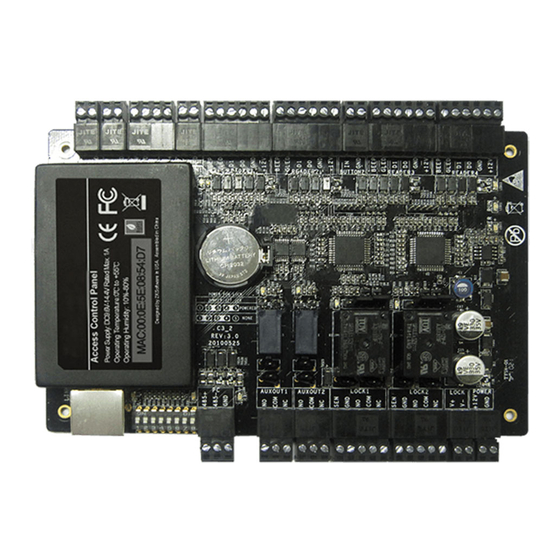
Summary of Contents for ZKaccess C3-200
- Page 1 www.zkteco.com...
-
Page 2: Table Of Contents
Safety Precautions Product Contents Product PIN Diagram LED indicators Product Dimension Installation of Panel with Casing Wire Legend Power Wiring Diagram WEIGAND Connection Exit button Connection Lock connection Door Sensor Connection Aux. Input Connection Aux. Output Connection Ethernet Connection RS485 Connection DIP switch settings Electrical Specifications Troubleshooting... -
Page 3: Safety Precautions
Safety Precautions The list below is to keep user’s safety and prevent any loss. Please read carefully before installation. Do not place the device next to Do not place a magnet near the Do not install the device in a heating equipment product. - Page 4 Safety Precautions The list below is to keep user’s safety and prevent any loss. Please read carefully before installation. Do not drop the device. Do not disassemble, repair or Do not use the device for any alter the device. other purpose than specified. Contact your nearest dealer in Do not damage the device In cleaning, do not splash water...
-
Page 5: Product Contents
Product Contents Basic Contents Wall mounting screws – 2 pcs. Wall Plugs– 2 pcs. Surge Suppressing Diode– 4 pcs. Software CD C3 installation guide screw driver – 2 pcs. C3-200... - Page 6 Product Contents Optional accessories RS485 convertor Weigand Card Reader Prox Card K1-1 Exit Button Door Sensor Alarm C3 Metal Case Card enroller...
-
Page 7: Product Pin Diagram
Product PIN Diagram SD Card Slot LED indicators LINK LED Aux Input 1 Ethernet Port LED solid green indicates Aux Input 4 LINK TCP/IP communication is ACT LED (Green) normal Reserved DIP Switch #1 Door Exit Flashing LED indicates data Button communication is in (Yellow) -
Page 8: Product Dimension
Product Dimension C3-200 106mm (4.17in.) Dimension(L*W):203.2× 10⁶ (mm) 6.30 ×4.17 (inches) 160mm (6.30in.) C3-Casing 330mm 330mm (13.0in.) (13.0in.) 90.5mm (3.56in.) Dimensions(L*W*H): 400 *90.5*330 (mm) 15.7× 13.0× 3.56 (inches) 400mm (15.7in.) -
Page 9: Installation Of Panel With Casing
Installation of Panel & Case Metal Case Power Supply Box Lock Hole C3 Panel Heat dissipation Hole Cable Conduit Backup Battery Thread Hole Wires need to be passed through Mounting the case on the wall this conduit... -
Page 10: Wire Legend
Wire Legend #2 K1-1 Exit Switch Detector Infrared sensors #1Exit Switch #1Card Reader #2 Card Reader 12V DC Power Floodlight Normal Open Lock LAN Cable RS485 Convertor Alarm Normal Close Lock Power Supply... -
Page 11: Power Wiring Diagram
Power wiring diagram Without Backup Battery C3-200 110-220V Switching power supply With Backup Battery C3-200 110-220V Backup Battery Switching power supply... -
Page 12: Weigand Connection
Weigand Connection Beeper Green LED Weigand D1 Weigand D0 DC+(6-14V) Weigand Card Reader Exit Button Connection DV12V(+) DV12V(-) ZK ABK Exit Button Notice: separate power supply K1-1 Exit Switch... -
Page 13: Lock Connection
Lock Connection Built-in Power Supply For Normally Open Lock Sensor Sensor 12V DC FR107 12V DC Built-in Power Supply For Normally Close Lock Sensor Sensor 12V DC FR107 12V DC... -
Page 14: Important Notes
Lock Connection Switching Wet Contact to Dry Contact Steps: Important Notes: Default setting C3-200 is set to supply lock power by default from external power supply , If you want to use built-in C3-200 4 Lock Relays Select one Relay power supply , you must do the following: 1. -
Page 15: Aux. Input Connection
Aux. I/O connection Aux. Input Connection 12V DC Aux. output Connection 12V DC... -
Page 16: Ethernet Connection
C3-200 signal connection. Direct connection To connect C3-200 with a PC directly, connect both devices with a straight network cable. As the C3-200 supports auto MDI/MDIX , it is not necessary to use a crossover type cable. CR10 Card Issuer... -
Page 17: Rs485 Connection
RS485 Connection #63 C3-200 RS485- RS485+ #1 C3-200 Important Notes Do's and Dont's for RS 485 connection 1. RS485 communication wires should be shielded or twisted pair calble. RS485 communication wires should be connected in a bus cascade instead of in a star form, to achieve a better shielding effect by reducing signal reflection during communications. -
Page 18: Dip Switch Settings
1. If you forget the C3 IP address or the device does not work 1. Number 8 is for setting the RS485 termination resistance. Putting the normally, you can use the number 7 terminal to restore C3-200 to switch to ON position is equivalent to parallel connection of a 120ohm factory default settings. -
Page 19: Electrical Specifications
Electrical Specifications Min. Typ. Max. Notes Working power supply Voltage(V) 14.4 Use regulated DC power adaptor only Current(A) Electronic lock relay output Switching voltage(V) Use regulated DC power adaptor only Switching Current(A) Auxiliary relay output Switching voltage(V) Use regulated DC power adaptor only Switching Current(A) 1.25 Switch Aux. -
Page 20: Troubleshooting
Card plus password 4. Can we integrate IP Camera and NVR Currently ZKACCESS software supports ZKAccess’ IP Cameras and NVR You can associate a camera to the door and setup a linkage for the same. 5. Can C3 panel support FR1200 fingerprint reader ? ... -
Page 21: Specifications
Specifications Communication RS485, TCP/IP Baud Rate for RS485 9600-115200 Power Supply 12V DC, 3A Card Holders Capacity 30,000 Log Events Capacity 100,000 LED Indicator Indication for communication, power, status and prox card 32-113 °F (0-45 °C) Environment Operating Humidity 20% to 80% Number of doors controlled Four Door (four door one way two door two way) - Page 22 Attached PC 485 Setting table Switch Setting Switch Setting Place Address Place Address Address No. Address No.
- Page 23 ZK USA office: 201 Circle Drive North, Suite 116 Piscataway, NJ 08854, USA Tel: +1 732-412-6007 Copyright 2013 ZKAccess Inc. All right reserved. Fax +1 732-412-6008 ZKTeco May, at any time and without notice , Make changes or sales@zkaccess.com improvements to the product and services offered and/or cease zkaccess.com...


Need help?
Do you have a question about the C3-200 and is the answer not in the manual?
Questions and answers