Sony GDM-C520 Service Manual
Trinitron series
Hide thumbs
Also See for GDM-C520:
- Operating instructions manual (91 pages) ,
- Limited warranty (2 pages)
Table of Contents
Advertisement
Quick Links
HISTORY INFORMATION FOR THE FOLLOWING MANUAL:
SERVICE MANUAL
ORIGINAL MANUAL ISSUE DATE: 12/2002
ALL REVISIONS AND UPDATES TO THE ORIGINAL MANUAL ARE APPENDED TO THE END OF THE PDF FILE.
REVISION DATE
12/2002
12/2002
3/2003
9-978-999-03
REVISION TYPE
SUBJECT
No revisions or updates are applicable at this time.
Correction - 1
Corrected critical items - Replaced Exploded View pages 34 & 35.
Supplement - 1
Added US Model
Added 5-5. Packing Materials (For GDM-C520K US Model Only) page 36-B
GDM-C520/C520K
21CR1
Design and specifications are subject to change without notice.
TRINITRON
COLOR MONITOR
®
AEP Model
Chassis No: SCC-L49B-A
CHASSIS
Advertisement
Table of Contents

Related Manuals for Sony GDM-C520


Summary of Contents for Sony GDM-C520
- Page 1 HISTORY INFORMATION FOR THE FOLLOWING MANUAL: GDM-C520/C520K SERVICE MANUAL AEP Model Chassis No: SCC-L49B-A 21CR1 CHASSIS ORIGINAL MANUAL ISSUE DATE: 12/2002 ALL REVISIONS AND UPDATES TO THE ORIGINAL MANUAL ARE APPENDED TO THE END OF THE PDF FILE. REVISION DATE...
- Page 2 Self Diagnosis Supported model GDM-C520/C520K SERVICE MANUAL AEP Model Chassis No: SCC-L49B-A 21CR1 CHASSIS GDM-C520K SPECIFICATIONS Picture tube 0.24 mm aperture grill pitch (center) Power Consumption 135 W 21 inches measured diagonally (with no USB devices connected) 90-degree deflection FD Trinitron...
-
Page 3: Table Of Contents
4-5. Semiconductors..........................31 SECTION 5: EXPLODED VIEW ........................... 33 5-1. Chassis............................33 5-2. Picture Tube ..........................34 5-3. Packing Materials (For GDM-C520 Only)..................35 5-4. Packing Materials (For GDM-C520K Only) ................... 36 SECTION 6: ELECTRICAL PARTS LIST......................37 — 3 —... -
Page 4: Power Management
GDM-C520/C520K POWER MANAGEMENT The power saving mode complies with the VESA Display Power Management Signaling standard. Each state of power management shall be activated by the host computer terminating the appropriate sync signals. Blanking the video must precede termination of the sync signals. The elapsed time counter shall also be controlled by the host computer. -
Page 5: Timing Specification
GDM-C520/C520K TIMING SPECIFICATION MODE AT PRODUCTION MODE 1 MODE 2 MODE 3 MODE 4 RESOLUTION 640 X 480 1600 X 1200 1920 X 1440 1920 X 1440 CLOCK 25.175 MHz 229.500 MHz 341.000 MHz 297.000 MHz --HORIZONTAL-- H-FREQ 31.469 kHz 106.250 kHz... -
Page 6: Warnings And Cautions
Les composants identifies par une trame et par une marque ! sur les schemas de principe, les vues explosees et les listes de pieces sont d’une importance critique pour la securite du fonctionnement. Ne les remplacer que par des composants Sony dont le numero de piece est indique dans le present manuel ou dans des supplements publies par Sony. -
Page 7: Safety Check-Out
GDM-C520/C520K SAFETY CHECK-OUT After correcting the original service problem, perform the following Leakage Test The AC leakage from any exposed metal part to earth ground and from safety checks before releasing the set to the customer: all exposed metal parts to any exposed metal part having a return to chassis, must not exceed 0.5 mA (500 microamperes). -
Page 8: Section 1: Disassembly
GDM-C520/C520K SECTION 1: DISASSEMBLY 1-1. CABINET REMOVAL Push in the tip of a screwdriver about 10mm to unlock the claw. Cabinet assembly Cabinet assembly Two claws Bezel Bezel Push the upper side of the cabinet assembly in the direction of arrow... -
Page 9: Service Position
GDM-C520/C520K 1-2. SERVICE POSITION Remove the D board. Remove the Video block assembly. Install the Adaptor board (XT MOUNT) (A-1391-123-A). Lay the Video block assembly. Video block assembly D board Install the video block assembly. Video block assembly Put a box which is about 15cm in height under the D board to fix it. -
Page 10: A1 Board (C Block) Removal
GDM-C520/C520K 1-3. A1 BOARD (C BLOCK) REMOVAL A1 board (C BLOCK) CN318 CN315 1-4. A1 BOARD REMOVAL Video case Screw (+BVTP 3 X 8) A1 board Four screws (+BVTP 3 x 8) CN315 Four screws (HEX) Video shield Two screws... -
Page 11: Bezel Assembly And H2 Board Removal
GDM-C520/C520K 1-5. BEZEL ASSEMBLY AND H2 BOARD REMOVAL Four tapping screws (5) Before removing the bezel assembly, secure the picture tube by attaching two screws to the picture tube shield at the positions shown with an arrow (diagonal two places) to prevent the picture tube from falling. -
Page 12: D Board Removal
GDM-C520/C520K 1-6. D BOARD REMOVAL Two screws (+BVTP 3 x 10) Video block assembly CN315 Rear plate assembly Five screws (+BVTP 3 x 10) A1 board CN1601 (C block) CN1600 Connector (4P) CN1103 CN1003 Two screws (+BVTT 4 x 8) -
Page 13: Picture Tube Removal
GDM-C520/C520K A1 board (C block) 1-7. PICTURE TUBE REMOVAL Anode cap Neck assembly Picture tube ANODE CAP REMOVAL WARNING: High voltage remains in the CRT even after the power is disconnected. To avoid electric shock, discharge CRT before attempting to remove the anode cap. -
Page 14: Harness Location
GDM-C520/C520K 1-8. HARNESS LOCATION H2 board CN1401 CN1400 Magnetic sensor CN1500 Picture tube L2 board CN1602 CN1600 CN1601 CN501 CN904 D board N board CN1103 CN604 CN1102 CN601 CN312 CN311 AC inlet (3P) CN315 CN320 A1 board CN318 CN319 — 14 —... -
Page 15: Section 2: Safety Related Adjustments
GDM-C520/C520K SECTION 2: SAFETY RELATED ADJUSTMENTS When replacing parts shown in the table below, the following 2-1. HV REGULATOR CIRCUIT CHECK operational checks must be performed as a safety precaution against X-ray emissions from the unit. Turn the RV901 slowly, and adjust so that high voltage is in the specified range. -
Page 16: Section 3: Adjustments
GDM-C520/C520K SECTION 3: ADJUSTMENTS Connect the communication cable of the connector located on the D Board on the monitor. Run the service software and then follow the instructions. 3-702-691-01 1-690-391-21 A-1500-819-A Connector Attachment Interface Unit IBM at Computer BUS CONNECTOR... -
Page 17: Convergence Rough Adjustment
GDM-C520/C520K 3-3. CONVERGENCE ROUGH 16. Adjust the vertical angle of the DY to make the top and bottom pins equal (a = b). The horizontal angle is not changed (straight). Settle ADJUSTMENT DY upright without leaning, and insert wedges firmly so that the DY does not move. -
Page 18: Vertical And Horizontal Position And Size Specification
GDM-C520/C520K 3-5. VERTICAL AND HORIZONTAL POSITION AND SIZE SPECIFICATION 4 : 3 MODE 1.8 mm 1.8 mm 3-6. FOCUS ADJUSTMENT Adjust Focus (V) and Focus (H) for optimum focus. Focus (V) Focus (H) — 18 —... -
Page 19: Section 4: Diagrams
GDM-C520/C520K SECTION 4: DIAGRAMS The components identified by shading and symbol are critical for safety. Replace only with part number specified. 4-1. CIRCUIT BOARDS LOCATION The symbol indicates a fast operating fuse and is displayed on the component side of the board. Replace only with fuse of the same rating as marked. -
Page 20: Block Diagrams
GDM-C520/C520K 4-3. BLOCK DIAGRAMS A1 BLOCK DIAGRAM, H2 BLOCK DIAGRAM, AND L2 BLOCK DIAGRAM CN309 HD15 IC008 IC001 IC002 INPUT SELECT RGB PRE-AMP RGB AMP CN315 CN318 V901 R OUT R IN R OUT R IN R OUT PICTURE TUBE... -
Page 21: Da Block Diagram And N Block Diagram
GDM-C520/C520K DA BLOCK DIAGRAM AND N BLOCK DIAGRAM (DPU) IC1001 CN1001 IC1101 LB DET P42/AN10 CN1101 IK SIGMA P41/AN09 H.DF HDF1 P86/SDA1 DDC SDA1 REFDC DCC2 P87/SCL1 DDC SCL1 CN1003 P21/A1/A17 DDC GND1 HD OUT HDOUT DDC SDA2 P84/SDA2 P54/AN04... -
Page 22: D Block Diagram
GDM-C520/C520K D BLOCK DIAGRAM PH610 +15V DEFLECTION , HDF, VDF, D610 AC IN T601 S601 IC640 CN602 F601 AC RECT :LFT +B DETECT ERROR AMP HV, POWER SUPPLY AC L AC N IC610 PFI IC620 REG OUT MAIN CONVERTER VG (H) -
Page 23: Schematics And Supporting Information
GDM-C520/C520K 4-4. SCHEMATICS AND SUPPORTING INFORMATION H2 BOARD SCHEMATIC DIAGRAM �� �� ����������� �� �� �� �� �� �� �� �� �� �� �� �� �� �� ��� �� � CN1401 � R1422 C1404 � 0.01 R1423 +12V Q1402 C1403 �... -
Page 24: D Board Schematic Diagram
GDM-C520/C520K D BOARD SCHEMATIC DIAGRAM �� �� ����������� �� �� �� �� �� �� �� �� �� �� �� �� �� �� ��� �� ��� �� ��� �� ��� �� ��� �� ��� �� ��� �� ��� �� ��� ��... - Page 25 GDM-C520/C520K [Deflection, HDF, VDF, HV, Power Supply] D BOARD LOCATOR LIST � � � � � � � � � �� �� �� DIODE DIODE TRANSISTOR D401 D901 Q501 D405 D906 Q502 � D501 D907 Q503 D502 D909 F-10 Q504...
-
Page 26: Da Board Schematic Diagram
GDM-C520/C520K DA BOARD SCHEMATIC DIAGRAM �� �� ����������� �� �� �� �� �� �� �� �� �� �� �� �� �� �� ��� �� ��� �� ��� �� ��� �� ��� �� ��� �� ��� �� [DSP] � H BLK... -
Page 27: N Board Schematic Diagram
GDM-C520/C520K N BOARD SCHEMATIC DIAGRAM �� �� ����������� �� �� �� �� �� �� �� �� �� �� �� �� �� �� ��� �� ��� �� ��� �� ��� �� ��� �� ��� �� ��� �� CN1003 [Micro] :S-MICRO(L) �... -
Page 28: L2 Board Schematic Diagram
GDM-C520/C520K L2 BOARD SCHEMATIC DIAGRAM �� �� ����������� �� �� �� �� �� �� �� �� �� �� �� �� �� �� ��� �� ��� �� ��� �� ��� �� ��� �� ��� �� ��� �� LCC-NS(+) � [CY, LCC]... -
Page 29: A1 Board Schematic Diagram
GDM-C520/C520K A1 BOARD SCHEMATIC DIAGRAM �� �� ����������� �� �� �� �� �� �� �� �� �� �� �� �� �� �� ��� �� ��� �� ��� �� ��� �� ��� �� ��� �� ��� �� CN315 CN316 J001 SG002... - Page 30 GDM-C520/C520K [Video] �� ����� ������� ���� �� ����� �� ������� ���� ����� ����� ����� ����� ����� �� ��� ���� ��� ���� ��� ���� ��� ���� ���� ��� ����� ��� � ��� � ���� � ����� � ��� ���� ��� �����...
-
Page 31: Semiconductors
GDM-C520/C520K 4-5. SEMICONDUCTORS CXD9563Q LM2412AT NJM78L05UA-TE1 SN74AHCT04NSR BA00AST-V5 LM2412T LA6500-FA 1 TOP VIEW 1 TOP VIEW 14pin SOP 64pin QFP STK391-120 NJM7812FA FA13842P MB88141PF-ER BA3953T-V5 SEB3-LF4 1 TOP VIEW 1 TOP VIEW 8pin DIP 10pin 24 pin SOP TC7SU04FU (TE85R) - Page 32 GDM-C520/C520K SEMICONDUCTORS (CONT.) DTA124ESA D4SB60L RM11A 2SC2362K-G DTZ10B DTA124ESA-TP D4SBL40 RM11C 2SC2362KG-AA DTZ13B DTC114ESA D4SBS4 MA111-(K8).S0 DTC114ESA-TP D4SBS4-F MA111-TX CATHODE DTC143XSA UDZ-TE-17-13B DTC143XSA-TP UDZ-TE-17-3.9B 2SC2459-GR-TPE4 UDZS-TE17-10B 2SC2784 UDZS-TE17-5.1B Ð UDZS-TE17-5.6B LETTER SIDE UDZS-TE17-9.1B E C B ANODE 1SS357-TPH3 Ð SML79423C-TP15...
-
Page 33: Section 5: Exploded View
GDM-C520/C520K SECTION 5: EXPLODED VIEW Components not identified by a part number or The component parts of an assembly are indicated by Items marked with an asterisk are not stocked since description are not stocked because they are seldom the reference numbers in the far right column of the parts they are seldom required for routine service. -
Page 34: Picture Tube
GDM-C520/C520K NOTE: The components identified by shading and mark are critical for safety. NOTE: Les composants identifies per un trame et une marque sont critiques Replace only with part number specified. pour la securite. Ne les remplacer que par une piece portant le numero specifie. -
Page 35: Packing Materials (For Gdm-C520 Only)
NOTE: Les composants identifies per un trame et une marque sont critiques Replace only with part number specified. pour la securite. Ne les remplacer que par une piece portant le numero specifie. 5-3. PACKING MATERIALS (FOR GDM-C520 ONLY) REF. NO. PART NO. DESCRIPTION... -
Page 36: Packing Materials (For Gdm-C520K Only)
GDM-C520/C520K NOTE: The components identified by shading and mark are critical for safety. NOTE: Les composants identifies per un trame et une marque sont critiques Replace only with part number specified. pour la securite. Ne les remplacer que par une piece portant le numero specifie. -
Page 37: Section 6: Electrical Parts List
The components in this manual identified by the following RESISTORS • All resistors are in ohms symbol: • F : nonflammable • All variable and adjustable resistors have characteristic curve B, unless otherwise noted. Items marked with an asterisk are not stocked since they are seldom required for routine service. - Page 38 GDM-C520/C520K NOTE: Les composants identifies per un trame et une NOTE: The components identified by shading marque sont critiques pour la securite. Ne les mark are critical for safety. Replace only remplacer que par une piece portant le numero specifie.
- Page 39 GDM-C520/C520K REF. NO. PART NO. DESCRIPTION VALUES REF. NO. PART NO. DESCRIPTION VALUES C641 1-107-792-11 CERAMIC 100pF C727 1-163-038-91 CERAMIC CHIP 0.1µF C642 1-136-189-00 MYLAR 0.1µF 250V C730 1-163-009-91 CERAMIC CHIP 0.001µF 10% C732 1-163-021-91 CERAMIC CHIP 0.01µF C643 1-107-792-11...
- Page 40 GDM-C520/C520K NOTE: Les composants identifies per un trame et une NOTE: The components identified by shading marque sont critiques pour la securite. Ne les mark are critical for safety. Replace only remplacer que par une piece portant le numero specifie.
- Page 41 GDM-C520/C520K NOTE: Les composants identifies per un trame et une NOTE: The components identified by shading marque sont critiques pour la securite. Ne les mark are critical for safety. Replace only remplacer que par une piece portant le numero specifie.
- Page 42 GDM-C520/C520K REF. NO. PART NO. DESCRIPTION VALUES REF. NO. PART NO. DESCRIPTION VALUES Q641 8-729-052-29 TRANSISTOR 2SK2876-01MR-F122 R516 1-216-667-11 METAL CHIP 4.7K 0.50% 1/10W Q652 8-729-029-66 TRANSISTOR DTC114ESA R517 1-216-691-11 METAL CHIP 0.50% 1/10W Q701 8-729-800-32 TRANSISTOR 2SC2362K-G R518 1-216-033-00...
- Page 43 GDM-C520/C520K REF. NO. PART NO. DESCRIPTION VALUES REF. NO. PART NO. DESCRIPTION VALUES R573 1-216-057-00 METAL CHIP 2.2K 1/10W R640 1-249-420-11 CARBON 1.8K 1/4W R574 1-216-295-00 SHORT CHIP 1/8W R641 1-216-675-11 METAL CHIP 0.50% 1/10W R642 1-216-001-00 METAL CHIP 1/10W...
- Page 44 GDM-C520/C520K REF. NO. PART NO. DESCRIPTION VALUES REF. NO. PART NO. DESCRIPTION VALUES R718 1-215-866-11 METAL OXIDE R908 1-249-429-11 CARBON 1/4W R719 1-216-373-11 METAL OXIDE R909 1-219-727-11 METAL R911 1-249-401-11 CARBON 1/4W R721 1-216-675-91 METAL CHIP 0.50% 1/10W R912 1-216-049-00...
- Page 45 A component identified by this NOTE: The components identified by shading mark are critical for safety. Replace only with part number specified. REF. NO. PART NO. DESCRIPTION VALUES REF. NO. PART NO. DESCRIPTION VALUES...
- Page 46 GDM-C520/C520K DA N REF. NO. PART NO. DESCRIPTION VALUES REF. NO. PART NO. DESCRIPTION VALUES DIODE R1139 1-216-691-11 METAL CHIP 0.50% 1/10W R1141 1-216-025-00 METAL CHIP 1/10W D1104 8-719-027-76 DIODE 1SS357-TPH3 R1142 1-216-295-91 SHORT CHIP D1105 8-719-067-40 DIODE STZ6.8N-T146 D1106...
- Page 47 GDM-C520/C520K N L2 REF. NO. PART NO. DESCRIPTION VALUES REF. NO. PART NO. DESCRIPTION VALUES FERRITE BEAD RB1006 1-233-576-11 RES, CHIP NETWORK 100 RB1007 1-233-576-11 RES, CHIP NETWORK 100 FB1001 1-543-963-22 FERRITE 0µH RB1009 1-233-576-11 RES, CHIP NETWORK 100 FB1005...
- Page 48 GDM-C520/C520K L2 A1 REF. NO. PART NO. DESCRIPTION VALUES REF. NO. PART NO. DESCRIPTION VALUES FB1602 1-412-911-11 FERRITE 0µH R1650 1-249-382-11 CARBON 1/4W FB1603 1-412-911-11 FERRITE 0µH R1651 1-249-382-11 CARBON 1/4W FB1604 1-412-911-11 FERRITE 0µH R1652 1-249-382-11 CARBON 1/4W R1653...
- Page 49 GDM-C520/C520K REF. NO. PART NO. DESCRIPTION VALUES REF. NO. PART NO. DESCRIPTION VALUES C040 1-163-021-91 CERAMIC CHIP 0.01µF C305 1-164-004-11 CERAMIC CHIP 0.1µF C042 1-115-339-11 CERAMIC CHIP 0.1µF C306 1-137-857-21 MYLAR 0.47µF 250V C043 1-164-004-11 CERAMIC CHIP 0.1µF C045 1-164-004-11 CERAMIC CHIP 0.1µF...
- Page 50 GDM-C520/C520K NOTE: Les composants identifies per un trame et une NOTE: The components identified by shading marque sont critiques pour la securite. Ne les mark are critical for safety. Replace only remplacer que par une piece portant le numero specifie.
- Page 51 GDM-C520/C520K REF. NO. PART NO. DESCRIPTION VALUES REF. NO. PART NO. DESCRIPTION VALUES Q004 8-729-025-28 TRANSISTOR 2SK1828 R048 1-216-691-11 METAL CHIP 0.50% 1/10W Q005 8-729-025-28 TRANSISTOR 2SK1828 R049 1-216-691-11 METAL CHIP 0.50% 1/10W Q101 8-729-120-28 TRANSISTOR 2SC1623-L5L6 R051 1-218-776-11 METAL CHIP 0.50% 1/10W...
- Page 52 0.50% 1/10W R308 1-216-667-11 METAL CHIP 4.7K 0.50% 1/10W R309 1-218-776-11 METAL CHIP 0.50% 1/10W R310 1-216-039-00 METAL CHIP 1/10W Sony Corporation English Sony Technology Center 2002LJ74WEB-1 Technical Services Printed in USA 9-978-999-03 Service Promotion Department © 2002.12 — 52 —...
- Page 53 D BOARD SCHEMATIC DIAGRAM ROTATION — CN701 R731 Q502 :CHIP KTC3876S-Y-RTK TO DA BOARD H DRV BUFF C734 R734 +12V CN1101 R738 R503 IC701 R501 6.8k B:CHIP LA6510 :CHIP +15V :CHIP CN502 D.TILT :CHIP C500 C559 — 220p R733 CH:CHIP R732 H.DF H.DF...
- Page 54 GDM-C520/C520K D BOARD IC VOLTAGE LIST IC401 IC620 IC654 IC901 volt volt volt volt 15.0 12.0 15.0 12.0 -13.4 12.0 -15.0 IC680 volt 14.3 -0.1 D518 RB441Q-40T-77 TO N BOARD C554 R522 CN1001 1000p B:CHIP :CHIP IC501 15.1 CN1104 IIC SDA...
- Page 55 :MPS D610 1/4W R904 D4SB60L R565 C904 C905 R564 R563 C906 D613 2.2k 470p R620 R693 100p :CHIP CH:CHIP RM11A 1/2W B:CHIP CH:CHIP 1/4W R675 T620 R692 — L611 2.2M IC620 D650 R615 1/2W 1/4W IC610 6.8k MCZ3001D D4SBL40 R691 R647 MZ1532 REG OUT...
- Page 56 R905 D921 C906 1SS119 :CHIP 100p +12V CH:CHIP CN1103 FB1005 FB1000 :S-MICRO :CHIP D917 +12V UDZS-TE17-9.1B WAKE UP KEY SCAN KEY SCAN Q702 R753 LED1 2SC2784-E LED1 :FPRD H DF OUT LED2 C911 LED2 D BOARD TRANSISTOR LIST C910 680p R739 FB1002 220p...
- Page 57 4-094-173-11(1) Color Reference System Quick Setup Guide Guide de démarrage rapide Guía de inicio rápido Kurzanleitung GDM-C520...
-
Page 59: Quick Start Guide
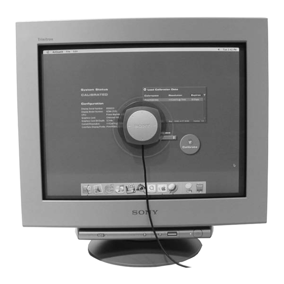
Note: Before connecting your GDM-C520 display, turn off your computer and unplug its power cable. Connect the GDM-C520 display's power cord to the display, and plug the cord into a nearby outlet. Press the power button on the front of the display to verify that the display powers up; then, press the power button again to power down the display before moving to Step 2. - Page 60 USB hub. Note: Make sure that the sensor can be placed easily over the center of your display screen, without stretching the sensor's cord. Attaching the Display Hood to your GDM-C520 Display Hook and loop tabs Unfold the hood.
-
Page 61: Troubleshooting Tips
Troubleshooting Tips Display Has No Power If the display power indicator is off and no image appears on the display, check the following: Ensure that the power cable is fully inserted into both the display's power port and a working electrical outlet. Test the electrical outlet by plugging in a working electrical device, such as a lamp. - Page 62 Make sure that your color settings are set to "millions" or at least 16-bit color. Make sure your display is set to "Professional" mode. To do this, press the "Picture Effect" button on the front of your GDM-C520 display until the on-screen display shows the text "Professional".
- Page 63 Raccordez le cordon d’alimentation du moniteur GDM-C520 au moniteur et branchez-le sur une prise de courant proche. Appuyez sur le bouton d’alimentation situé à l’avant du moniteur pour vérifier que celui-ci se met bien sous tension, puis appuyez de nouveau sur le bouton d’alimentation pour mettre le moniteur hors tension avant de passer à...
- Page 64 USB. Remarque: Assurez-vous que le capteur peut être placé facilement sur le centre du moniteur, sans étirer le cordon du capteur. Fixation du protecteur d’écran sur le moniteur GDM-C520 Encoches de crochets et de boucles Dépliez le protecteur d’écran.
- Page 65 Conseils de dépannage Le moniteur n’est pas alimenté Si le voyant d’alimentation du moniteur est éteint et qu’aucune image ne s’affiche à l’écran, vérifiez les points suivants: Assurez-vous que le câble d’alimentation est complètement inséré dans le port d’alimentation du moniteur et dans une prise secteur en état de fonctionnement.
- Page 66 CD Artisan Color Reference System. Si l’aide fournie dans le manuel d’utilisateur contenu sur le CD n’est pas suffisante, vous pouvez contacter Sony via l’URL suivante : http://www.sony.com/displays/support, ou par téléphone au : 1-866-256-9392.
- Page 67 Nota: Antes de conectar el monitor GDM-C520, apague el ordenador y desenchufe el cable de alimentación del mismo. Conecte el cable de alimentación del monitor GDM-C520 a este último y enchufe el cable a una toma de corriente próxima. Pulse el botón de encendido de la parte frontal del monitor para comprobar que éste se enciende; a continuación, pulse de nuevo el botón de encendido para apagar el monitor antes de proceder con el paso 2.
- Page 68 USB. Nota: Asegúrese de que el sensor puede colocarse sin problemas en el centro de la pantalla del monitor sin estirar el cable del sensor. Colocación de la visera en el monitor GDM-C520 Pestañas de enganche Despliegue la visera.
- Page 69 Sugerencias para la solución de problemas El monitor no recibe alimentación Si el indicador de alimentación del monitor está apagado y no aparece ninguna imagen en la pantalla, compruebe lo siguiente: Asegúrese de que el cable de alimentación está completamente insertado en el puerto de alimentación del monitor y en una toma de corriente que funcione.
- Page 70 Si necesita ayuda en la instalación del monitor o en la calibración del sistema, consulte el manual del usuario incluido en el CD del sistema de Color Reference. Si a pesar de ello sigue precisando ayuda, póngase en contacto con Sony por teléfono llamando al número 1-866-256-9392 o bien visite...
- Page 71 Hinweis: Bevor Sie den Bildschirm GDM-C520 anschließen, schalten Sie den Computer aus und ziehen den Netzstecker aus der Steckdose. Schließen Sie das Netzkabel des Bildschirms GDM-C520 an den Bildschirm an und stecken Sie den Stecker des Netzkabels in eine Steckdose in der Nähe.
- Page 72 Hinweis: Stellen Sie sicher, dass der Sensor problemlos über der Mitte des Bildschirms aufgestellt werden kann, ohne dass das Kabel des Sensors gespannt wird. Anbringen der Bildschirmhaube am Bildschirm GDM-C520 Fixierlaschen Falten Sie die Haube auseinander. Bringen Sie die Fixierlaschen wie in der Abbildung oben dargestellt an der Unterseite der Bildschirmhaube an.
- Page 73 Störungsbehebung Bildschirm wird nicht mit Strom versorgt Wenn die Netzanzeige des Bildschirms nicht leuchtet und kein Bild auf dem Bildschirm erscheint, überprüfen Sie bitte Folgendes: Sehen Sie nach, ob das Netzkabel vollständig in den Netzanschluss am Bildschirm und in eine funktionstüchtige Netzsteckdose eingesteckt ist.
- Page 74 Wenn Sie weitere Informationen zum Konfigurieren des Bildschirms oder Kalibrieren des Systems benötigen, schlagen Sie bitte im Benutzerhandbuch auf der Artisan Color Reference System-CD nach. Wenn Sie darüber hinaus Unterstützung brauchen, wenden Sie sich an Sony unter http://www.sony.com/displays/support oder telefonisch unter 1-866-256-9392.
- Page 76 Sony Corporation Printed in USA...
-
Page 77: Schematic Diagrams
PRINTING THE SERVICE MANUAL The PDF of this service manual is not designed to be printed from cover to cover. The pages vary in size, and must therefore be printed in sections based on page dimensions. NON-SCHEMATIC PAGES Data that does NOT INCLUDE schematic diagrams are formatted to 8.5 x 11 inches and can be printed on standard letter-size and/or A4-sized paper. SCHEMATIC DIAGRAMS The schematic diagram pages are provided in two ways, full size and tiled. - Page 78 ON-SCREEN SEARCH OPTION All of the text within the service manual PDF is content searchable. This means that you can enter any text, word, phrase or reference number that appears in the manual, and the PDF software will search, fi nd and move the cursor to the location where you requested text fi rst appears. This feature can be particularly useful in locating components on a specifi...
- Page 79 SCREW (M4) (EXT TOOTH WASHER) 1-782-784-32 CORD SET, POWER 1-782-784-32 CORD SET, POWER Design and specifications are subject to change without notice. TRINITRON COLOR MONITOR ® Sony Corporation English Sony Technology Center 2002LJ74WEB-1 Technical Services Printed in USA Service Promotion Department © 2002.12 9-978-999-91...
- Page 80 Self Diagnosis Supported model GDM-C520/C520K SERVICE MANUAL AEP Model US Model Chassis No: SCC-L49B-A 21CR1 CHASSIS SUPPLEMENT- 1 SUBJECT: ADDED US MODEL, ADDED PACKING MATERIALS FOR US MODEL Correct the service manual as shown. File this Supplement with the service manual.
- Page 81 CUSHION, LOWER 4-094-208-01 CARTON, INDIVIDUAL 4-041-255-23 BAG, PROTECTION X-4040-802-2 CASE ASSY, SENSOR 1-824-656-12 CABLE ASSY (DIGITAL CABLE) 4-091-105-02 HOOD Sony Corporation English Sony Technology Center 2003CJ74WEB-1 Technical Services Printed in USA Service Promotion Department © 2003.3 9-978-999-81 — 36-B —...
Need help?
Do you have a question about the GDM-C520 and is the answer not in the manual?
Questions and answers