Table of Contents
Advertisement
Rev. 1.2
Assembly Instructions
Spray Valve SMS-02
Article Number:
NOTE
Please read the Assembly Instructions carefully before first using the incomplete device and
strictly adhere to the instructions!
The incomplete device may only be worked with and worked on by persons who are familiar
with the assembly instructions and the current regulations for industrial safety and accident
prevention.
Always keep this translated version of the "Original Assembly Instructions" at the incomplete
Assembly Instructions - Spray Valve SMS-02
S02-....
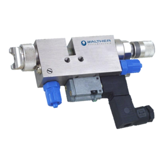
Picture: Spray Valve SMS-02 with flat air cap and raster-needle lock
device! The instructions have to be available anytime!
Walther Systemtechnik GmbH – D 76726 Germersheim
Telefon: +49 (0)7274-7022-0 Telefax: +49 (0)7274-7022-91
http://www.walther-2000.de – info@walther-2000.de
Page 1 of 34
Advertisement
Table of Contents

Related Manuals for Walther SMS-02


Summary of Contents for Walther SMS-02
- Page 1 Assembly Instructions Spray Valve SMS-02 Article Number: S02-…. Picture: Spray Valve SMS-02 with flat air cap and raster-needle lock NOTE Please read the Assembly Instructions carefully before first using the incomplete device and strictly adhere to the instructions! The incomplete device may only be worked with and worked on by persons who are familiar with the assembly instructions and the current regulations for industrial safety and accident prevention.
-
Page 2: Table Of Contents
Assembly Instructions - Spray Valve SMS-02 Rev. 1.2 Page 2 of 34 Table of Contents Page EC DECLARATION OF INCORPORATION ........................4 INTRODUCTION ..............................5 ......................5 ARGET ROUP OF THE SSEMBLY NSTRUCTIONS ............................5 IST OF IGNS AND YMBOLS SAFETY................................ - Page 3 Spare Part List for SMS-02 (Standard) ....................21 10.4 SMS-02 (R ) ................. 22 PARE RAWINGS ASTER EEDLE ETECTION 10.4.1 Spare Part List for SMS-02 (Raster-Needle Detection) ................23 10.5 .......................... 24 RTICLE UMBERS FOR 10.6 ........................... 25 RTICLE UMBERS FOR OZZLES 10.7...
-
Page 4: Ec Declaration Of Incorporation
Assembly Instructions - Spray Valve SMS-02 Rev. 1.2 Page 4 of 34 EC Declaration of Incorporation in accordance with EU Machinery Directive 2006/42/EU, dated 17 May 2006, Appendix II B We herewith confirm that the below mentioned incomplete device meets the basic requirements for safety and health as stated in EU Machinery Directive 2006/42/EU for its design and construction as well as for the configuration released by us on the market. -
Page 5: Introduction
/ electronic residual energies. 2.3 Warranty and Liability According to the conditions laid down by the German Engineering Association (VDMA), Walther Sys- temtechnik GmbH has a guarantee of 12 months under normal European operating conditions on its own parts (spare parts are excluded);... -
Page 6: Correct Use
Assembly Instructions - Spray Valve SMS-02 Rev. 1.2 Page 6 of 34 2.4 Correct Use This device is a needle valve and will be used for processing materials which can be sprayed in continuous or intermitting operation. Under no circumstances shall aggressive media such as acids, alkaline solutions, detergents, chemicals or others be sprayed. -
Page 7: Transport
4 Description of Function The spray valves of SMS-02 series are suitable for the application of liquid up to viscous media, such as grease, oil, separating agents, colors or glues. One of the major characteristics of SMS-02 series is the integrated spray air valve with which you can adjust the post-spray duration for cleaning the nozzles. -
Page 8: Technical Data
Assembly Instructions - Spray Valve SMS-02 Rev. 1.2 Page 8 of 34 4.2 Technical Data General Data Size with flat-jet air cap [mm] 130 x 80 x 22 Size with round-jet air cap [mm] 127 x 80 x 22 Weight [g] ca. -
Page 9: Total View / Description
Assembly Instructions - Spray Valve SMS-02 Rev. 1.2 Page 9 of 34 5.2 Total View / Description Basic casing Nozzle with air cap and retainer ring Raster needle lock 5/2-way magnetic valve Material connection Connection for atomizer air Connection for control air 2x Fastening thread M5 5.3 Adjusting the Device... -
Page 10: Sms-02 With Raster-Needle Detection
Assembly Instructions - Spray Valve SMS-02 Rev. 1.2 Page 10 of 34 5.4 SMS-02 with Raster-Needle Detection Optionally, you can use a raster-needle lock with a pre-installed, inductive proximity switch. It will release a signal when the needle piston with the needle is open. This will help you in digitally monitoring the status „nozzle open“. -
Page 11: Installation Diagram For Color-Marking Systems
Spray valves of the SMS-02 series generally operates with a control pressure of 5 - 6 bar. The atomizer pressure has to be lower than the material pressure in order to avoid a repulse of the material. Atomized air pressure and material pressure should be closely correlated. -
Page 12: Operating Elements
Assembly Instructions - Spray Valve SMS-02 Rev. 1.2 Page 12 of 34 If the pause time is a multiple of the spray time, the valve must be sprayed free in a separate location or the spray valve should be operated several times to optimize the application. -
Page 13: Maintenance And Repair
7 Maintenance and Repair 7.1 General Information The spray valves of the SMS-02 series are high-quality precision devices which will not fail if treated correctly and will operate almost maintenance-free. All mobile parts should be regularly oiled and also the threads should be greased when the nozzles are cleaned or exchanged. -
Page 14: Exchanging The Sealing Bush (6.0.0)
Assembly Instructions - Spray Valve SMS-02 Rev. 1.2 Page 14 of 34 7.6 Exchanging the Sealing Bush (6.0.0) Unscrew raster-needle lock completely (9.0.3) Remove air cap (1.1.0) with retainer ring (3.1.0) Unscrew nozzle (2.1.0) Carefully push needle (7.0.0) from the nozzle side to the back ... -
Page 15: Spare Parts
Assembly Instructions - Spray Valve SMS-02 Rev. 1.2 Page 15 of 34 After longer system standstills (e.g. 2-3 weeks), the complete system will be cleaned before re-start. If necessary, the material hoses and if applicable, also the inlays of the pressure tank have to be re- placed. -
Page 16: Troubleshooting
Page 16 of 34 8 Troubleshooting 8.1 General Information IMPORTANT First check all supply lines for connection and serviceability. In case of serious problems that cannot be resolved, please contact the Walther Systemtechnik GmbH customer service. 8.2 Failures: Fault Possible Cause... -
Page 17: Spray Image/ Type Of Defect
Assembly Instructions - Spray Valve SMS-02 Rev. 1.2 Page 17 of 34 8.3 Spray Image/ Type of defect SPRAY IMAGE PROBLEM CAUSE ACTION Normal Spray Image (Flat jet) Normal Spray Image (Round jet) Soiled Spray image shaped air cap too much... -
Page 18: Taking Out Of Service
Assembly Instructions - Spray Valve SMS-02 Rev. 1.2 Page 18 of 34 9 Taking out of Service 9.1 Short Interruption A short interruption (15 min or more) has to be followed by a fine spraying. IMPORTANT Please follow the Operating Manual! 9.2 Long-term Interruption... -
Page 19: Appendix
Assembly Instructions - Spray Valve SMS-02 Rev. 1.2 Page 19 of 34 10 Appendix 10.1 Dimensioned Drawing (Flat jet) 10.2 Dimensioned Drawing (Round jet) Walther Systemtechnik GmbH – D 76726 Germersheim Telefon: +49 (0)7274-7022-0 Telefax: +49 (0)7274-7022-91 http://www.walther-2000.de – info@walther-2000.de... -
Page 20: Spare Parts Drawing Sms-02 (Standard)
Assembly Instructions - Spray Valve SMS-02 Rev. 1.2 Page 20 of 34 10.3 Spare Parts Drawing SMS-02 (Standard) IMPORTANT Air control valve and return check valve are available only as complete! Walther Systemtechnik GmbH – D 76726 Germersheim Telefon: +49 (0)7274-7022-0 Telefax: +49 (0)7274-7022-91... -
Page 21: Spare Part List For Sms-02 (Standard)
Assembly Instructions - Spray Valve SMS-02 Rev. 1.2 Page 21 of 34 10.3.1 Spare Part List for SMS-02 (Standard) Pos. Article-No. Description 1.1.0 Air cap 2.1.0 Nozzle 3.1.0 97410028 Retainer ring 4.1.0 97510030 Main body 5.0.0 979504.000 Material wear-and-tear set complete 5.0.0... -
Page 22: Spare Part Drawings Sms-02 (Raster-Needle Detection)
Assembly Instructions - Spray Valve SMS-02 Rev. 1.2 Page 22 of 34 10.4 Spare Part Drawings SMS-02 (Raster-Needle Detection) IMPORTANT Air control valve and return check valve are available only as complete! Walther Systemtechnik GmbH – D 76726 Germersheim Telefon: +49 (0)7274-7022-0 Telefax: +49 (0)7274-7022-91... -
Page 23: Spare Part List For Sms-02 (Raster-Needle Detection)
Assembly Instructions - Spray Valve SMS-02 Rev. 1.2 Page 23 of 34 10.4.1 Spare Part List for SMS-02 (Raster-Needle Detection) Pos. Article-No. Description 1.1.0 Air cap 2.1.0 Nozzle 3.1.0 97410028 Retainer ring 4.1.0 97510590 Main body 5.0.0 979504.000 Material wear-and-tear set complete 5.0.0... -
Page 24: Article Numbers For Air Caps
Assembly Instructions - Spray Valve SMS-02 Rev. 1.2 Page 24 of 34 10.5 Article Numbers for Air Caps 1.1.0 Air cap, Flat jet, Standard, 45° (Ø20x14.5mm) Article-No. Description 97310038 Air cap, Flat jet, 0.2-1.0mm 97310039 Air cap, Flat jet, 1.2-1.5mm 97310231 Air cap, Flat jet, 1.8-2.0mm... -
Page 25: Article Numbers For Nozzles
Assembly Instructions - Spray Valve SMS-02 Rev. 1.2 Page 25 of 34 1.1.0 Air cap, Round jet, Standard, 15° (Ø20x11mm) Article-No. Description 97310034 Air cap, Round jet, 0.2-1.0mm 97310035 Air cap, Round jet, 1.2-1.5mm 97310080 Air cap, Round jet, 1.8-2.0mm 97310091 Air cap, Round jet, 2.5mm... - Page 26 Assembly Instructions - Spray Valve SMS-02 Rev. 1.2 Page 26 of 34 2.1.0 Nozzle, KLS, stainless steel (Ø12x17.2mm) Article-No. Description 97210119 Nozzle, KLS, 0.2mm 97210120 Nozzle, KLS, 0.3mm 97210121 Nozzle, KLS, 0.5mm 97210122 Nozzle, KLS, 0.8mm 97210123 Nozzle, KLS, 1.0mm 97210124 Nozzle, KLS, 1.2mm...
-
Page 27: Article Numbers For Nozzle Needles
Assembly Instructions - Spray Valve SMS-02 Rev. 1.2 Page 27 of 34 10.7 Article Numbers for Nozzle Needles 7.0.0 Nozzle needle complete, Standard, Marking, Special spin (Ø3x72.5mm) Article-No. Description 97112508 Nozzle needle, Standard, 0.2/0.3mm 97110471 Nozzle needle, Standard, 0.5mm 97111251 Nozzle needle, Standard, 0.8mm... -
Page 28: Article Numbers For Valves
Assembly Instructions - Spray Valve SMS-02 Rev. 1.2 Page 28 of 34 10.8 Article Numbers for Valves 11.0.0 Air Control Valve Article-No. Description 97800016 Air control valve for atomizer air pressure > 1,8 bar 97800132 Air control valve for atomizer air pressure < 1,8 bar 17.0.0... -
Page 29: Article Numbers For Other Parts
Assembly Instructions - Spray Valve SMS-02 Rev. 1.2 Page 29 of 34 Threaded joint for connection „Material M“ 21.2.0 Article-No. Description 975165100656 Threaded joint G1/8 (for hose 6mm) 11.118-6 Threaded joint G1/8 (for hose 6mm) 11.118-8 Threaded joint G1/8 (for hose 8mm) -
Page 30: Wear-And-Tear Parts
Assembly Instructions - Spray Valve SMS-02 Rev. 1.2 Page 30 of 34 10.11 Wear-and-Tear Parts Material wear-and-tear set complete for SMS-02 (Standard and Needle query) Consisting of: # Pos. 5.1.0 (Variseal) # Pos. 5.3.0 (O-ring) # Pos. 5.4.0 (protection sleeve) # Pos. -
Page 31: Accessories
Assembly Instructions - Spray Valve SMS-02 Rev. 1.2 Page 31 of 34 10.12 Accessories Figure Article Number Description Nozzle Extension 97xxxxxx (see also Product Catalog ACCESSORIES) 97410042 Retainer ring hexagonal 97410059 Retainer ring stainless steel Hot Plate 979565.001 (see also Product Catalog ACCESSORIES) - Page 32 Assembly Instructions - Spray Valve SMS-02 Rev. 1.2 Page 32 of 34 Needle Detection The mounting of the needle setection will be made factory-side. It will be integrated in the raster needle lock (Pos. 9.0 Spare Part List). If ordered as spare part, please note that a complete raster needle lock will be delivered as the initiator has to be set at the factory and also glued in.
-
Page 33: Description Pneumatic Needle-Stroke Adjustment 97800037
Assembly Instructions - Spray Valve SMS-02 Rev. 1.2 Page 33 of 34 10.13 Description Pneumatic Needle-Stroke Adjustment 97800037 Description of Function The pneumatic Needle Stroke Adjustment (PNA) is used for a remote-controlled change between two nee- dle-stroke settings. The front regulating screw (1; see pic.) determines the minimum needle stroke of the spraying device for a PNA with applied pressure. - Page 34 Assembly Instructions - Spray Valve SMS-02 Rev. 1.2 Page 34 of 34 Pos. Article No. Description 97610172 Raster head 97610170 Regulating hollow spindle 97820000 Pressure spring 97320022 Cylinder pin DIN 6325 97320196 Regulating button 97710021 Piston complete 97320145 Piston rod...
Need help?
Do you have a question about the SMS-02 and is the answer not in the manual?
Questions and answers