Table of Contents

Subscribe to Our Youtube Channel
Related Manuals for Galil DMC-1510


Summary of Contents for Galil DMC-1510
- Page 1 USER MANUAL DMC-1500 Manual Rev. 2.0xf By Galil Motion Control, Inc. Galil Motion Control, Inc. 270 Technology Way Rocklin, California 95765 Phone: (916) 626-0101 Fax: (916) 626-0102 Internet Address: support@galilmc.com URL: www.galilmc.com Rev 05-06...
- Page 2 WARNING: Machinery in motion can be dangerous! It is the responsibility of the user to design effective error handling and safety protection as part of the machine. Galil shall not be liable or responsible for any incidental or consequential damages.
- Page 3 Firmware Updates New feature for Rev 2.0h April 1998: Feature Description 1. CMDERR enhanced to support multitasking: If CMDERR occurs on thread 1,2 or 3, thread will be holted. Thread can be re-started with XQ _ED2, _ED1, 1 for retry XQ _ED3, _ED1, 1 for next instruction 2.
- Page 4 Feature Description 1. Operand ‘&’ and ‘|’ for conditional statements Allows for multiple conditional statements in jump routines IE. (A>=3) & (B<55) | (C=78) New feature for Rev 2.0 March 1996. (This revision is also designated DMC-1500-18). DAC resolution increased to 16-bits. Step motor control method improved.
- Page 5 (KPXZ=10 is invalid. Only one or all axes can be specified at a time). New commands added July 1993 Rev 1.2: Command Description Gives available variables Give available labels @COM[n] 2's complement function New commands added March 1993: Rev 1.2 Command Description Segment counter in LM, VM and CM modes...
-
Page 7: Table Of Contents
............ 9 Step 4. Connect AC Power to the Controller .............. 9 Step 5. Install Communications Software ..............9 Step 6. Establish Communications with Galil Software..........10 Step 7. Connect Amplifiers and Encoders..............11 Step 8a. Connect Standard Servo Motors..............13 Step 8b. - Page 8 Baud Rate Selection ....................34 Daisy-Chaining......................35 Daisy Chain Example: ....................35 Synchronizing Sample Clocks...................36 Controller Response to DATA ....................36 Galil Software Tools and Libraries..................36 Chapter 5 Command Basics Introduction..........................37 Command Syntax........................37 Coordinated Motion with more than 1 axis ...............38 Program Syntax ......................38 Controller Response to DATA ....................38...
- Page 9 Chapter 6 Programming Motion Overview ..........................41 Independent Axis Positioning....................41 Command Summary - Independent Axis ..............42 Operand Summary - Independent Axis ..............42 Independent Jogging........................ 44 Command Summary - Jogging .................. 44 Operand Summary - Independent Axis ..............44 Linear Interpolation Mode.......................
- Page 10 Commenting Programs ....................82 Executing Programs & Multitasking ..................83 Debugging Programs .......................84 Debugging Programs .......................86 Commands.........................86 Operands........................86 Program Flow Commands .......................87 Event Triggers & Trippoints ..................87 DMC-1500 Event Triggers..................88 Event Trigger Examples: ...................88 Conditional Jumps .....................91 Subroutines........................94 Stack Manipulation....................94 Auto-Start Routine.....................95 Automatic Subroutines for Monitoring Conditions...........95 Mathematical and Functional Expressions...
- Page 11 Backlash Compensation by Sampled Dual-Loop............ 123 Chapter 8 Hardware & Software Protection Introduction ........................... 126 Hardware Protection ......................126 Output Protection Lines................... 126 Input Protection Lines ..................... 126 Software Protection ....................... 127 Programmable Position Limits ................127 Off-On-Error ......................127 Automatic Error Routine ..................
- Page 12 JD4 - 20 pin IDC - Amplifiers.................154 JD6 - Daughterboard Connector (60 pin)..............154 Cable Connections for DMC-1500 ..................154 Standard RS-232 Specifications ................154 DMC-1500 Serial Cable Specifications..............155 Pin-Out Description for DMC-1500 ..................157 Configuration Description for DMC-1500 ................159 Jumpers........................159 Address Configuration Jumpers ................159 Front Panel Baud Rate Switches ................159...
-
Page 13: Chapter 1 Overview
Chapter 1 Overview Introduction The DMC-1500 Series are packaged motion controllers designed for stand-alone operation. Features include coordinated motion profiling, uncommitted inputs and outputs, non-volatile memory for stand-alone operation and RS232/RS422 communication. Extended performance capability over the previous generation of controllers includes: fast 8 MHz encoder input frequency, precise 16-bit motor command output DAC, +/-2 billion counts total travel per move, faster sample rate, and multitasking of up to four programs. -
Page 14: Overview Of Motor Types
Standard servo motors with +/- 10 volt command signals Step motors with step and direction signals Other actuators such as hydraulics - For more information, contact Galil. The user can configure each axis for any combination of motor types, providing maximum flexibility. -
Page 15: Microcomputer Section
Microcomputer Section The main processing unit of the DMC-1500 is a specialized 32-bit Motorola 68340 Series Microcomputer with 256K RAM, 64 K EPROM and 128 K bytes EEPROM. The RAM provides memory for variables, array elements and application programs. The EPROM stores the firmware of the DMC-1500. -
Page 16: Motor
A motor converts current into torque which produces motion. Each axis of motion requires a motor sized properly to move the load at the desired speed and acceleration. Galil's Motion Component Selector software can help you calculate motor size and drive size requirements. Contact Galil at 800- 377-6329 if you would like this product. - Page 17 error light for each axis will also turn on at this stage. A reset is required to restore the DMC-1500 to normal operation. Consult the factory for a Return Materials Authorization (RMA) Number if your DMC-1500 is damaged. Chapter 1 Overview • 5 DMC-1500...
- Page 18 THIS PAGE LEFT BLANK INTENTIONALLY 6 • Chapter 1 Overview DMC-1500...
-
Page 19: Chapter 2 Getting Started
Power Amplifiers for motors Power Supply for Amplifiers PC (Personal Computer with RS232 port) Software from Galil (Optional - but strongly recommended for first time users) Communication Disk (COMMdisk) -AND - WSDK-16 Servo Design Software for Windows 3.1, and 3.11 for Workgroups... -
Page 20: Installing The Dmc-1500
Before setting up the motion control system, the user must determine the desired motor configuration. The DMC-1500 can control any combination of standard servo motors, and stepper motors. Other types of actuators, such as hydraulics can also be controlled, please consult Galil. The following configuration information is necessary to determine the proper motor configuration:... -
Page 21: Step 3. Configure Dip Switches On The Dmc-1500
After you have installed the DMC-1500 controller and turned the power on to your computer, you should install software that enables communication between the controller and PC. There are several ways to do this. The easiest way is to use the communication disks available from Galil (COMMDISK VOL1 FOR DOS AND VOL2 FOR WINDOWS). -
Page 22: Step 6. Establish Communications With Galil Software
Registry.) Use the Add button to add a new entry to the Registry. You will need to supply the Galil Controller type. For any address changes to take effect, a model number must be entered. If you are changing an existing controller, this field will already have an entry. -
Page 23: Step 7. Connect Amplifiers And Encoders
If you are not properly communicating with the controller, the program will pause for 3-15 seconds. The top of the screen will display the message “Status: not connected with Galil motion controller” and the following error will appear: “STOP - Unable to establish communication with the Galil controller. - Page 24 If you are not sure about the potential of the ground levels, connect the two ground signals (amplifier ground and earth) by a 10 KΩ resistor and measure the voltage across the resistor. Only if the voltage is zero, connect the two ground signals directly. The amplifier enable signal is used by the controller to disable the motor.
-
Page 25: Step 8A. Connect Standard Servo Motors
Step by step directions on servo system setup are also included on the WSDK (Windows Servo Design Kit) software offered by Galil. See section on WSDK for more details. Step A. Check the Polarity of the Feedback Loop It is assumed that the motor and amplifier are connected together and that the encoder is operating correctly (Step B). - Page 26 TL 1 <CR> Note: Once the correct polarity of the feedback loop has been determined, the torque limit should, in general, be increased to the default value of 9.99. The servo will not operate properly if the torque limit is below the normal operating range. See description of TL in the command reference.
- Page 27 (Typically Red Connector) Figure 2-2 - System Connections with the AMP-1100Amplifier. Note: this figure shows a Galil Motor and Encoder which uses a flat ribbon cable to connect to the AMP-1100 unit. Chapter 2 Getting Started • 15...
-
Page 28: Step 8B. Connect Step Motors
ICM-1100 Pin 2 Screw Terminals Pin 1 Encoder Wire Connections +5V (103) Encoder: ICM-1100: GND (104) Channel A(+) XI+ (81) XI- (82) Channel B(+) XB+ (79) XB- (80) Channel A- XA- (78) XA+ (77) Channel B- Encoder Wires Index Pulse Index Pulse - (Typically Red Connector) DC Servo Motor... -
Page 29: Step 9. Tune The Servo System
Adjusting the tuning parameters is required when using servo motors. The system compensation provides fast and accurate response. The following presentation suggests a simple and easy way for compensation. More advanced design methods are available with software design tools from Galil, such as the Servo Design Kit (SDK software ) The filter has three parameters: the damping, KD;... -
Page 30: Design Examples
For a more detailed description of the operation of the PID filter and/or servo system theory, see Chapter 10 - Theory of Operation. Design Examples Here are a few examples for tuning and using your controller. These examples have remarks next to each command - these remarks must not be included in the actual program. -
Page 31: Example 3 - Multiple Axes
Example 3 - Multiple Axes Objective: Move the four axes independently. Instruction Interpretation PR 500,1000,600,-400 Distances of X,Y,Z,W SP 10000,12000,20000,10000 Slew speeds of X,Y,Z,W AC 100000,10000,100000,100000 Accelerations of X,Y,Z,W DC 80000,40000,30000,50000 Decelerations of X,Y,Z,W BG XZ Start X and Z motion BG YW Start Y and W motion Example 4 - Independent Moves... -
Page 32: Example 6 - Absolute Position
TE X Tell error - X axis only TE Y Tell error - Y axis only TE Z Tell error - Z axis only TE W Tell error - W axis only Example 6 - Absolute Position Objective: Command motion by specifying the absolute position. Instruction Interpretation DP 0,2000... -
Page 33: Example 9 - Interrogation
Increase the torque level gradually by instructions such as Instruction Interpretation TL 1.0 Increase torque limit to 1 volt. TL 9.98 Increase torque limit to maximum, 9.98 Volts. The maximum level of 10 volts provides the full output torque. Example 9 - Interrogation The values of the parameters may be interrogated. -
Page 34: Example 12 - Motion Programs With Loops
Example 12 - Motion Programs with Loops Motion programs may include conditional jumps as shown below. Instruction Interpretation Label DP 0 Define current position as zero V1=1000 Set initial value of V1 #Loop Label for loop PA V1 Move X motor V1 counts BG X Start X motion AM X... -
Page 35: Example 15 - Linear Interpolation
SP 2000 Set speed Move X Wait until move is complete WT 500 Wait 500 ms V1 = _TPX Determine distance to zero PR -V1/2 Command X move 1/2 the distance Start X motion After X moved WT 500 Wait 500 ms Report the value of V1 JP #C, V1=0 Exit if position=0... - Page 36 CR 2000,90,-180 Circular segment VS 1000 Vector speed VA 50000 Vector acceleration VD 50000 Vector deceleration End vector sequence Start motion (-4000,4000) (0,4000) R=2000 (-4000,0) (0,0) local zero Figure 2-4 Motion Path for Example 16 24 • Chapter 2 Getting Started DMC-1500...
-
Page 37: Chapter 3 Connecting Hardware
Chapter 3 Connecting Hardware Overview The DMC-1500 provides optoisolated digital inputs for forward limit, reverse limit, home, and abort signals. The controller also has 8 optoisolated, uncommitted inputs (for general use) as well as 8 TTL outputs and 7 analog inputs configured for voltages between +/- 10 volts. Controllers with 5 or more axes have an additional 8 TTL level inputs and 8 TTL level outputs. -
Page 38: Home Switch Input
Home Switch Input The Home inputs are designed to provide mechanical reference points for a motion control application. A transition in the state of a Home input alerts the controller that a particular reference point has been reached by a moving part in the motion control system. A reference point can be a point in space or an encoder index pulse. -
Page 39: Uncommitted Digital Inputs
All motion programs that are currently running are terminated when a transition in the Abort input is detected. For information on setting the Off-On-Error function, see the Command Reference, OE. NOTE: The error LED does not light up when the Abort Input is active. Uncommitted Digital Inputs The DMC-1500 has 8 uncommitted opto-isolated inputs. -
Page 40: Using An Isolated Power Supply
IN9-IN16 INCOM FLE,RLE,HOMEE LSCOM FLF,RLF,HOMEF FLG,RLG,HOMEG FLH,RLH,HOMEH A logic zero is generated when at least 1mA of current flows from the common signal to the input. A positive voltage (with respect to the input) must be supplied at the common. This can be accomplished by connecting a voltage in the range of +5V to +28V into INCOM of the input circuitry from a separate power supply LSCOM... -
Page 41: Bypassing The Opto-Isolation
Ω 1 mA < V supply/(R + 2.2K ) < 15 mA (For Voltages > +28V) LSCOM 2.2K Isolated Supply Figure 3-2. Connecting a single Limit or Home Switch to an Isolated Supply NOTE: As stated in Chapter 2, the wiring is simplified when using the ICM-1100 or AMP-11x0 interface board. -
Page 42: Changing Optoisolated Inputs From Active Low To Active High
LSCOM Figure 3-3 - Connecting Limit switches to the internal 5V supply Changing Optoisolated Inputs From Active Low to Active High Some users may prefer that the optoisolated inputs be active high. For example, the user may wish to have the inputs be activated with a logic one signal. The limit, home and latch inputs can be configured through software to be active high or low with the CN command. -
Page 43: Ttl Inputs
10 KΩ. The analog inputs are specified as AN[x] where x is a number 1 thru 7. Galil can supply the DMC-1500 with a 16-bit A/D converter as an option. Chapter 3 Connecting Hardware • 31... -
Page 44: Ttl Outputs
TTL Outputs The DMC-1500 provides eight general use outputs and an error signal output. The general use outputs are TTL and are accessible by connections to OUT1 thru OUT8. These outputs can be turned On and Off with the commands, SB (Set Bit), CB (Clear Bit), OB (Output Bit), and OP (Output Port). -
Page 45: Chapter 4 Communication
Chapter 4 Communication Introduction The DMC-1500 has two RS232 ports. The main port is the data set and the auxiliary port is the data term. The main port can be configured through the switches on the front panel, and the auxiliary port can be configured with the software command CC. -
Page 46: Rs422 - Auxiliary Port {P2
3 Receive Data - input 8 Receive+ input 4 RTS - input 9 RTS+ input 5 Ground *RS422 - Auxiliary Port {P2} 1 CTS - input 6 CTS+ input 2 Receive Data - input 7 Receive+ input 3 Transmit Data - output 8 Transmit+ output 4 RTS - output 9 RTS+ output... -
Page 47: Daisy-Chaining
p - Echo - 0=Off; 1=On; Valid only if r=0 Note, for the handshake of the auxiliary port, the roles for the RTS and CTS lines are reversed. Example: CC 1200,0,0,1 Configure auxiliary communication port for 1200 baud, no handshake, general port mode and echo turned on. -
Page 48: Synchronizing Sample Clocks
API (Application Programming Interface) software is available from Galil. The API software is written in C and is included in the Galil COMM disks. They can be used for development under DOS and Windows environments (16 and 32 bit Windows). With the API's, the user can incorporate already existing library functions directly into a C program. -
Page 49: Chapter 5 Command Basics
DMC-1500 command interpreter. Note: If you are using a Galil terminal program, commands will not be processed until an <enter> command is given. This allows the user to separate many commands on a single line and not begin execution until the user gives the <enter>... -
Page 50: Coordinated Motion With More Than 1 Axis
PRX=1000 Specify a position relative movement for the X axis of 1000 ACY=200000 Specify acceleration for the Y axis as 200000 Instead of data, some commands request action to occur on an axis or group of axes. For example, ST XY stops motion on both the X and Y axes. -
Page 51: Interrogating The Controller
?TC1 <enter> Tell Code command 1 Unrecognized command Returned response There are many reasons for receiving an invalid command response. The most common reasons are: unrecognized command (such as typographical entry or lower case), command given at improper time (such as during motion), or a command out of range (such as exceeding maximum speed). A complete list of all error codes can be found with the description of the TC command in the Command Reference Manual. -
Page 52: Additional Interrogation Methods
Additional Interrogation Methods. Most commands can be interrogated by using a question mark. For information specific to a particular axis, type the command followed by a ? for each axis requested. PR ?,?,?,? Request X,Y,Z,W values PR ,? Request Y value only The controller can also be interrogated with operands. -
Page 53: Chapter 6 Programming Motion
These modes are discussed in the following sections. The DMC-1510 is a single axis controller and uses X-axis motion only. Likewise, the DMC-1520 uses X and Y, the DMC-1530 uses X,Y and Z, and the DMC-1540 uses X,Y,Z and W. The DMC- 1550 uses A,B,C,D, and E. -
Page 54: Command Summary - Independent Axis
Command Summary - Independent Axis COMMAND DESCRIPTION PR X,Y,Z,W Specifies relative distance PA x,y,z,w Specifies absolute position SP x,y,z,w Specifies slew speed AC x,y,z,w Specifies acceleration rate DC x,y,z,w Specifies deceleration rate BG XYZW Starts motion ST XYZW Stops motion before end of move IP x,y,z,w Changes position target IT x,y,z,w... - Page 55 Example - Multiple Move Sequence Required Motion Profiles: X-Axis 500 counts Position 10000 count/sec Speed 500000 counts/sec 2 Acceleration Y-Axis 1000 counts Position 15000 count/sec Speed 500000 counts/sec 2 Acceleration Z-Axis 100 counts Position 5000 counts/sec Speed 500000 counts/sec Acceleration This example will specify a relative position movement on X, Y and Z axes.
-
Page 56: Independent Jogging
Notes on fig 6.1: The X and Y axis have a ‘trapezoidal’ velocity profile, while the Z axis has a ‘triangular’ velocity profile. The X and Y axes accelerate to the specified speed, move at this constant speed, and then decelerate such that the final position agrees with the command position, PR. The Z axis accelerates, but before the specified speed is achieved, must begin deceleration such that the axis will stop at the commanded position. -
Page 57: Linear Interpolation Mode
Example - Jog in X Only Jog X motor at 50000count/s. After X motor is at its jog speed, begin jogging Z in reverse direction at 25000 count/s. AC 20000,,20000 Specify X,Z acceleration of 20000 cts/sec DC 20000,,20000 Specify X,Z deceleration of 20000 cts/sec JG 50000,,-25000 Specify jog speed and direction for X and Z axis BG XY... -
Page 58: Specifying Vector Acceleration, Deceleration And Speed
The Linear End (LE) command must be used to specify the end of a linear move sequence. This command tells the controller to decelerate to a stop following the last LI command. If an LE command is not given, an Abort AB1 must be used to abort the motion sequence. It is the responsibility of the user to keep enough LI segments in the DMC-1500 sequence buffer to ensure continuous motion. -
Page 59: Command Summary - Linear Interpolation
AV 4000 Set trippoint to wait until vector distance of 4000 is reached VS 1000 Change vector speed AV 5000 Set trippoint to wait until vector distance of 5000 is reached VS 4000 Change vector speed Program end Specifying Vector Speed for Each Segment The instruction VS has an immediate effect and, therefore, must be given at the required time. -
Page 60: Operand Summary - Linear Interpolation
Linear End- Required at end of LI command sequence Returns the length of the vector (resets after 2147483647) Trippoint for After Sequence complete AV n Trippoint for After Relative Vector Distance, n S curve smoothing constant for vector moves Operand Summary - Linear Interpolation OPERAND DESCRIPTION Return distance traveled... - Page 61 The resulting profile is shown in Figure 6.2. 30000 27000 POSITION W 3000 4000 36000 40000 POSITION Z FEEDRATE TIME (sec) VELOCITY Z-AXIS TIME (sec) VELOCITY W-AXIS TIME (sec) Figure 6.2 - Linear Interpolation Example - Multiple Moves This example makes a coordinated linear move in the XY plane. The Arrays VX and VY are used to store 750 incremental distances which are filled by the program #LOAD.
-
Page 62: Vector Mode: Linear And Circular Interpolation Motion
#LOAD Load Program DM VX [750],VY [750] Define Array COUNT=10 Initialize Counter N=10 Initialize position increment #LOOP LOOP VX [COUNT]=N Fill Array VX VY [COUNT]=N Fill Array VY N=N+10 Increment position COUNT=COUNT+1 Increment counter JP #LOOP,COUNT<750 Loop if array not full Label LM XY Specify linear mode for XY... -
Page 63: Specifying Vector Acceleration, Deceleration And Speed
The command, VP xy specifies the coordinates of the end points of the vector movement with respect to the starting point. Non-sequential axes do not require comma delineation. The command, CR r,q,d define a circular arc with a radius r, starting angle of q, and a traversed angle d. The notation for q is that zero corresponds to the positive horizontal direction, and for both q and d, the counter-clockwise (CCW) rotation is positive. - Page 64 Both cases assign a vector speed of n count/s to the corresponding motion segment. Changing Feedrate: The command VR n allows the feedrate, VS, to be scaled between 0 and 10 with a resolution of .0001. This command takes effect immediately and causes VS scaled. VR also applies when the vector speed is specified with the ‘<’...
-
Page 65: Command Summary - Vector Mode Motion
AM XYZ When the move is complete Engage knife WT50 Wait 50 msec for the knife to engage Do the circular cut After the coordinated move is complete Disengage knife MG "ALL DONE" End program Command Summary - Vector Mode Motion COMMAND DESCRIPTION VM m,n... -
Page 66: Electronic Gearing
Example: Traverse the path shown in Fig. 6.3. Feedrate is 20000 counts/sec. Plane of motion is XY Instruction Interpretation VM XY Specify motion plane VS 20000 Specify vector speed VA 1000000 Specify vector acceleration VD 1000000 Specify vector deceleration VP -4000,0 Segment AB CR 1500,270,-180 Segment BC... -
Page 67: Command Summary - Electronic Gearing
The command GAX or GAY or GAZ or GAW (or GAA or GAB or GAC or GAD or GAE or GAF or GAG or GAH for DMC-1580) specifies the master axis. There may only be one master. GR x,y,z,w specifies the gear ratios for the slaves where the ratio may be a number between +/-127.9999 with a fractional resolution of .0001. - Page 68 Example - Simple Master Slave Master axis moves 10000 counts at slew speed of 100000 counts/sec. Y is defined as the master. X,Z,W are geared to master at ratios of 5,-.5 and 10 respectively. Instruction Interpretation Specify master axes as Y GR 5,,-.5,10 Set gear ratios PR ,10000...
-
Page 69: Electronic Cam
Define master axis as X GR,2 Set gear ratio 2:1 for Y PR,300 Specify correction distance SP,5000 Specify correction speed AC,100000 Specify correction acceleration DC,100000 Specify correction deceleration Start correction Electronic Cam The electronic cam is a motion control mode which enables the periodic synchronization of several axes of motion. - Page 70 EM 6000,1500 Step 3. Specify the master interval and starting point. Next we need to construct the ECAM table. The table is specified at uniform intervals of master positions. Up to 256 intervals are allowed. The size of the master interval and the starting point are specified by the instruction: EP m,n where m is the interval width in counts, and n is the starting point.
- Page 71 where n=1 enables ECAM mode and n=0 disables ECAM mode. Step 6. Engage the slave motion To engage the slave motion, use the instruction EG x,y,z,w where x,y,z,w are the master positions at which the corresponding slaves must be engaged. If the value of any parameter is outside the range of one cycle, the cam engages immediately.
- Page 72 the equation: Y = 0.5 * X + 100 sin (0.18 * X) where X is the master, with a cycle of 2000 counts. The cam table can be constructed manually, point by point, or automatically by a program. The following program includes the set-up.
-
Page 73: Command Summary - Ecam Mode
Command Summary - ECAM Mode command description EA ABCDEFG or H Specify ECAM master axis EB n (n = 0 or 1) Enable ECAM EG a,b,c,d,e,f,g,h ECAM go - Specifies position for engaging ECAM EM a,b,c,d,e,f,g,h Specify cam cycle EP m,n Specifies cam table interval and starting point EQ a,b,c,d,e,f,g,h Quit ECAM... - Page 74 EQ2000,2000 Disengage X and Y when Master = 2000 MF,, 2000 Wait until the Master goes to 2000 ST Z Stop the Z axis motion EB 0 Exit the ECAM mode End of the program The above example shows how the ECAM program is structured and how the commands can be given to the controller.
-
Page 75: Contour Mode
Contour Mode The DMC-1500 also provides a contouring mode. This mode allows any arbitrary position curve to be prescribed for 1 to 8 axes. This is ideal for following computer generated paths such as parabolic, spherical or user-defined profiles. The path is not limited to straight line and arc segments and the path length may be infinite. -
Page 76: Additional Commands
POSITION (COUNTS) TIME (ms) SEGMENT 1 SEGMENT 2 SEGMENT 3 Figure 6.4 - The Required Trajectory Additional Commands The command, WC, is used as a trippoint "When Complete". This allows the DMC-1500 to use the next increment only when it is finished with the previous one. Zero parameters for DT followed by zero parameters for CD exit the contour mode. - Page 77 General Velocity Profiles The Contour Mode is ideal for generating any arbitrary velocity profiles. The velocity profile can be specified as a mathematical function or as a collection of points. The design includes two parts: Generating an array with data points and running the program. Generating an Array - An Example Consider the velocity and position profiles shown in Fig.
-
Page 78: Teach (Record And Play-Back)
the difference between the positions is computed and is stored in the array DIF. Finally the motors are run in the contour mode. Contour Mode Example Instruction Interpretation #POINTS Program defines X points DM POS[16] Allocate memory DM DIF[15] Set initial conditions, C is index T is time in ms V1=50*T V2=3*T... -
Page 79: Stepper Motor Operation
DM C[n] Dimension array RA C[] Specify array for automatic record (up to 8 arrays) RD _TPX Specify data for capturing (such as _TPX or _TPZ) RC n,m Specify capture time interval where n is 2n msec, m is number of records to be captured RC? or _RC Returns a 1 if recording Record and Playback Example:... -
Page 80: Specifying Stepper Motor Operation
Specifying Stepper Motor Operation In order to command stepper motor operation, the appropriate stepper mode jumpers must be installed. See chapter 2 for this installation. Stepper motor operation is specified by the command MT. The argument for MT is as follows: 2 specifies a stepper motor with active low step output pulses -2 specifies a stepper motor with active high step output pulses 2.5 specifies a stepper motor with active low step output pulses and reversed direction... -
Page 81: Using An Encoder With Stepper Motors
of the buffer. The command, DP sets the value of the step count register as well as the value of the reference position. For example, DP 0, defines the reference position of the X axis to be zero. Stepper Smoothing Filter Output Motion Profiler Output Buffer... -
Page 82: Dual Loop (Auxiliary Encoder)
Contains the value of the main encoder Dual Loop (Auxiliary Encoder) The DMC-1500 provides an interface for a second encoder for each axis except for axes configured for stepper motor operation. When used, the second encoder is typically mounted on the motor or the load, but may be mounted in any position. - Page 83 Continuous dual loop Sampled dual loop To illustrate the problem, consider a situation in which the coupling between the motor and the load has a backlash. To compensate for the backlash, position encoders are mounted on both the motor and the load.
-
Page 84: Command Summary - Using The Auxiliary Encoder
Start motion #Correct Correction loop Wait for motion completion V1=10000-_DEX Find linear encoder error V2=-_TEX/4+V1 Compensate for motor error JP#END,@ABS[V2]<2 Exit if error is small PR V2*4 Correction move Start correction JP#CORRECT Repeat #END Command Summary - Using the Auxiliary Encoder COMMAND DESCRIPTION Configure Encoder Type... - Page 85 The smoothing function is specified by the following commands: IT x,y,z,w Independent time constant VT n Vector time constant The command, IT, is used for smoothing independent moves of the type JG, PR, PA and the command, VT, is used to smooth vector moves of the type VM and LM. The smoothing parameters, x,y,z,w and n are numbers between 0 and 1 and determine the degree of filtering.
-
Page 86: Using The Ks Command (Step Motor Smoothing)
Figure 6.6 - Trapezoidal velocity and smooth velocity profiles Using the KS Command (Step Motor Smoothing): When operating with step motors, motion smoothing can be accomplished with the command, KS. The KS command smoothes the frequency of step motor pulses. Similar to the commands, IT and VT, this produces a smooth velocity profile. - Page 87 Example 1 - Using Home Command Instruction Interpretation #HOME Label AC 1000000 Acceleration Rate DC 1000000 Deceleration Rate SP 5000 Speed for Home Search HM X Home X BG X Begin Motion AM X After Complete MG "AT HOME" Send Message Example 2 - Using Find Edge Command Instruction Interpretation...
- Page 88 Figure 6.7 - Motion intervals in the Home sequence 76 • Chapter 6 Programming Motion DMC-1500...
-
Page 89: High Speed Position Capture (The Latch Function)
High Speed Position Capture (The Latch Function) Often it is desirable to capture the position precisely for registration applications. The DMC-1500 provides a position latch feature. This feature allows the position of X,Y,Z or W to be captured within 25 microseconds of an external low input signal. The general inputs 1 through 4, and 9 through 12 correspond to each axis. - Page 90 THIS PAGE LEFT BLANK INTENTIONALLY 78 • Chapter 6 Programming Motion DMC-1500...
-
Page 91: Chapter 7 Application Programming
1500 editor or remotely using another editor and then downloading the program into the controller. (Galil's Terminal and SDK software provides an editor and UPLOAD and DOWNLOAD utilities). The DMC-1500 provides a line Editor for entering and modifying programs. The Edit mode is entered with the ED instruction. -
Page 92: Edit Mode Commands
Line numbers appear as 000,001,002 and so on. Program commands are entered following the line numbers. Multiple commands may be given on a single line as long as the total number of characters doesn't exceed the limits given above. While in the Edit Mode, the programmer has access to special instructions for saving, inserting and deleting program lines. -
Page 93: Program Format
Program Format A DMC-1500 program consists of DMC-1500 instructions combined to solve a machine control application. Action instructions, such as starting and stopping motion, are combined with Program Flow instructions to form the complete program. Program Flow instructions evaluate real-time conditions, such as elapsed time or motion complete, and alter program flow accordingly. -
Page 94: Commenting Programs
Commenting Programs There are two methods for commenting programs. The first method uses the NO command and allows for comments to be embedded into Galil programs. The second method used the REM statement and requires the use of Galil software. -
Page 95: Executing Programs & Multitasking
#PATH REM 2-D CIRCULAR PATH VMXY REM VECTOR MOTION ON X AND Y VS 10000 REM VECTOR SPEED IS 10000 VP -4000,0 REM BOTTOM LINE CR 1500,270,-180 REM HALF CIRCLE MOTION VP 0,3000 REM TOP LINE CR 1500,90,-180 REM HALF CIRCLE MOTION REM END VECTOR SEQUENCE REM BEGIN SEQUENCE MOTION REM END OF PROGRAM... -
Page 96: Debugging Programs
Multitasking Example: Producing Waveform on Output 1 Independent of a Move. Instruction Interpretation #TASK1 Task1 label Initialize reference time Clear Output 1 #LOOP1 Loop1 label AT 10 Wait 10 msec from reference time Set Output 1 AT -40 Wait 40 msec from reference time, then initialize reference Clear Output 1 JP #LOOP1 Repeat Loop1... - Page 97 Error Code Command When there is a program error, the DMC-1500 halts the program execution at the point where the error occurs. To display the last line number of program execution, issue the command, MG _ED. The user can obtain information about the type of error condition that occurred by using the command, TC1.
-
Page 98: Debugging Programs
The command, DM ?, will return the number of array elements currently available. The command, DA ?, will return the number of arrays currently available. For example, a standard DMC-1510 will have a maximum of 8000 array elements in up to 30 arrays. If an array of 100 elements is defined, the command DM ? will return the value 1500 and the command DA ? will return 13. -
Page 99: Program Flow Commands
The operand _DM returns the number of available array elements. Debugging Example: The following program has an error. It attempts to specify a relative movement while the X-axis is already in motion. When the program is executed, the controller stops at line 003. The user can then query the controller using the command, TC1. -
Page 100: Dmc-1500 Event Triggers
DMC-1500 Event Triggers Command Function AM X Y Z W or S Halts program execution until motion is complete on the specified axes or motion sequence(s). AM with no parameter (A B C D E F G H) tests for motion complete on all axes. This command is useful for separating motion sequences in a program. - Page 101 Instruction Interpretation #TWOMOVE Label PR 2000 Position Command Begin Motion Wait for Motion Complete PR 4000 Next Position Move Begin 2nd move End program Event Trigger - Set Output after Distance Set output bit 1 after a distance of 1000 counts from the start of the move. The accuracy of the trippoint is the speed multiplied by the sample period.
- Page 102 Instruction Interpretation #INPUT Program Label AI-1 Wait for input 1 low PR 10000 Position command Begin motion End program Event Trigger - Set Output When At Speed Instruction Interpretation #ATSPEED Program Label JG 50000 Specify jog speed AC 10000 Acceleration rate Begin motion Wait for at slew speed 50000 Set output 1...
-
Page 103: Conditional Jumps
Event Trigger - Multiple Move with Wait This example makes multiple relative distance moves by waiting for each to be complete before executing new moves. Instruction Interpretation #MOVES Label PR 12000 Distance SP 20000 Speed AC 100000 Acceleration Start Motion AD 10000 Wait a distance of 10,000 counts SP 5000... - Page 104 Using the JP Command: The JP command will cause the controller to execute commands at the location specified by the label or line number if the condition of the jump statement is satisfied. If no condition is specified, program execution will automatically jump to the specified line. If the condition is not satisfied, the controller will continue to execute the next commands in the program sequence.
- Page 105 In this example, this statement will cause the program to jump to the label #TEST if V1 is less than V2 and V3 is less than V4. To illustrate this further, consider this same example with an additional condition: JP #TEST, ((V1<V2) & (V3<V4)) | (V5<V6) This statement will cause the program to jump to the label #TEST under two conditions;...
-
Page 106: Subroutines
Logical Operators: OPERATOR DESCRIPTION < less than > greater than equal to <= less than or equal to >= greater than or equal to <> not equal Subroutines A subroutine is a group of instructions beginning with a label and ending with an end command (EN). Subroutines are called from the main program with the jump subroutine instruction JS, followed by a label or line number, and conditional statement. -
Page 107: Auto-Start Routine
Auto-Start Routine The DMC-1500 has a special label for automatic program execution. A program which has been saved into the controllers non-volatile memory can be automatically executed upon power up or reset by beginning the program with the label #AUTO. The program must be saved into non-volatile memory using the command, BP. - Page 108 NOTE: The #LIMSWI will continue to be executed until the limit switch is cleared (goes high). Example - Position Error Instruction Interpretation #LOOP Dummy Program JP #LOOP;EN Loop #POSERR Position Error Routine V1=_TEX Read Position Error MG "EXCESS POSITION ERROR" Print Message MG "ERROR=",V1= Print Error...
- Page 109 (greater than 8 million), the #CMDERR routine will be executed prompting the operator to enter a new number. Example - Communication Interrupt A DMC-1510 is used to move the X axis back and forth from 0 to 10000. This motion can be paused, resumed and stopped via input from an auxiliary port terminal. Instruction...
-
Page 110: Mathematical And Functional Expressions
JP #LOOP Continually loop to make back and forth motion End main program #COMINT Interrupt Routine Clear interrupt JP #STOP,P2CH="0" Check for S (stop motion) JP #PAUSE,P2CH="1" Check for P (pause motion) JP #RESUME,P2CH="2" Check for R (resume motion) EN1,1 Do nothing #STOP Routine for stopping motion... -
Page 111: Bit-Wise Operators
Bit-Wise Operators The mathematical operators & and | are bit-wise operators. The operator, &, is a Logical And. The operator, |, is a Logical Or. These operators allow for bit-wise operations on any valid DMC-1500 numeric operand, including variables, array elements, numeric values, functions, keywords, and arithmetic expressions. -
Page 112: Functions
To illustrate further, if the user types in the string “TESTME” at the input prompt, the controller will respond with the following: Response from command MG LEN6 {S1} Response from command MG LEN5 {S1} Response from command MG LEN4 {S1} Response from command MG LEN3 {S1} Response from command MG LEN2 {S1} Response from command MG LEN1 {S1}... -
Page 113: Assigning Values To Variables
Examples - Valid Variable Names POSX POS1 SPEEDZ Examples - Invalid Variable Names Variable Problem REALLONGNAME Cannot have more than 8 characters Cannot begin variable name with a number SPEED Z Cannot have spaces in the name Assigning Values to Variables: Assigned values can be numbers, internal variables and keywords, functions, controller parameters and strings;... -
Page 114: Operands
Example - Using Variables for Joystick The example below reads the voltage of an X-Y joystick and assigns it to variables VX and VY to drive the motors at proportional velocities, where 10 Volts = 3000 rpm = 200000 c/sec Speed/Analog input = 200000/10 = 20000. -
Page 115: Special Operands (Keywords)
Special Operands (Keywords) The DMC-1500 provides a few operands which give access to internal variables that are not accessible by standard DMC-1500 commands. Keyword Function _BGn *Is equal to a 1 if motion on axis ‘n’ is complete, otherwise equal to 0. *Is equal to the number of arrays available *Is equal to the number of available labels for programming *Is equal to the available array memory... -
Page 116: Assignment Of Array Entries
Example - Using the Command, DM Instruction Interpretation DM POSX[7] Defines an array names POSX with seven entries DM SPEED[100] Defines an array named speed with 100 entries DM POSX[0] Frees array space Assignment of Array Entries Like variables, each array element can be assigned a value. Assigned values can be numbers or returned values from instructions, functions and keywords. -
Page 117: Automatic Data Capture Into Arrays
Uploading and Downloading Arrays to On Board Memory Arrays may be uploaded and downloaded using the QU and QD commands. QU array[],start,end,delim QD array[],start,end where array is an array name such as A[]. Start is the first element of array (default=0) End is the last element of array (default=last element) Delim specifies whether the array data is separated by a comma (delim=1) or a carriage return (delim=0). -
Page 118: Operand Summary - Automatic Data Capture
_TSX Switches (only bit 0-4 valid) _SCX Stop code _NOX Status bits _TTX Torque (reports digital value +/-8097) Note: X may be replaced by Y,Z or W for capturing data on other axes, or A,B,C,D,E,F,G,H for DMC-1580. Operand Summary - Automatic Data Capture Operand Description Returns a 0 or 1 where, 0 denotes not recording, 1 specifies recording in progress... -
Page 119: Input Of Data (Numeric And String)
Input of Data (Numeric and String) Input of Data The command, IN, is used to prompt the user to input numeric or string data. Using the IN command, the user may specify a message prompt by placing a message in quotations. When the controller executes an IN command, the controller will wait for the input of data. -
Page 120: Operator Data Entry Mode
Operator Data Entry Mode The Operator Data Entry Mode permits data to be entered at anytime. In this mode, the input will not be interpreted as DMC commands and input such as ST or JG will not be recognized as commands. In this mode, the DMC-1500 provides a buffer for receiving characters. - Page 121 Don't interrupt Port 2 Interrupt on <enter> Port 2 Interrupt on any character Port 2 Clear any characters in buffer Disable operator data mode for P1 Enable operator data mode for P1 The #COMINT label is used for the communication interrupt. For example, the DMC-1500 can be configured to interrupt on any character received on Port 2.
-
Page 122: Output Of Data (Numeric And String)
ZS1;CI2;JP#PRINT Jump to Print #B;JS#NUM SPEEDY=VAL New Y speed ZS1;CI2;JP#PRINT Jump to Print #C;ST;AMX;CI-1 Stop motion on S MG{^8}, "THE END" ZS;EN,1 End-Re-enable interrupt #NUM Routine for entering new jog speed MG "ENTER",PICH{S},"AXIS SPEED" {N} Prompt for value #NUMLOOP; CI-1 Check for enter #NMLP Routine to check input from terminal... -
Page 123: Specifying The Serial Port For Messages
In addition to variables, functions and commands, responses can be used in the message command. For example: MG "Analog input is", @AN[1] MG "The Gain of X is", _GNX Specifying the Serial Port for Messages: By default, messages will be sent through port 1, the main serial port. The serial port can be specified with the specifier, {P1} for the main serial port and {P2} for auxiliary serial port. -
Page 124: Using The Mg Command To Configure Terminals
Using the MG Command to Configure Terminals The MG command can be used to configure a terminal. Any ASCII character can be sent by using the format {^n} where n is any integer between 1 and 255. Example: MG {^07} {^255} sends the ASCII characters represented by 7 and 255 to the bus. - Page 125 Using the PF Command to Format Response from Interrogation Commands The command, PF, can change format of the values returned by theses interrogation commands: BL ? LE ? DE ? PA ? DP ? PR ? EM ? TN ? FL ? VE ? IP ?
-
Page 126: Formatting Variables And Array Elements
Tell Position Interrogation Command -9, 5, 0, 7 Response from Interrogation Command (Without Leading Zeros) Local Formatting of Response of Interrogation Commands The response of interrogation commands may be formatted locally. To format locally, use the command, {Fn.m} or {$n.m} on the same line as the interrogation command. The symbol F specifies that the response should be returned in decimal format and $ specifies hexadecimal. -
Page 127: Converting To User Units
Instruction Interpretation V1=10 Assign V1 Return V1 0000000010.0000 Response from controller with default format V1={F4.2} Specify local format 0010.00 Response from controller with new format V1={$4.2} Specify hex format $000A.00 Response from controller in hexadecimal format V1="ALPHA" Assign string "ALPHA" to V1 V1={S4} Specify string format first 4 characters ALPH... -
Page 128: Digital Inputs
Example - Using Set Bit and Clear Bit Commands (SB, CB) Instruction Interpretation Sets bit 6 of output port Clears bit 4 of output port Clear bit 9 of output port on DMC-1580 The Output Bit (OB) instruction is useful for setting or clearing outputs depending on the value of a variable, array, input or expression. -
Page 129: Input Interrupt Function
Example - Using Inputs to control program flow: Instruction Interpretation JP #A,@IN[1]=0 Jump to A if input 1 is low JP #B,@IN[2]=1 Jump to B if input 2 is high AI 7 Wait until input 7 is high AI -6 Wait until input 6 is low Example - Start Motion on Switch Motor X must turn at 4000 counts/sec when the user flips a panel switch to on. -
Page 130: Analog Inputs
MG "Interrupt occurred" Display message ST XY Stops motion on X and Y axes #LOOP Loop until Interrupt cleared JP #LOOP,@IN[1]=0 JG 15000,10000 Specify new speeds WT 300 Wait 300 milliseconds BG XY Begin motion on X and Y axes Return from Interrupt subroutine Analog Inputs The DMC-1500 provides seven analog inputs. -
Page 131: Example Applications
VE=VP-_TPX Find position error VEL=VE*20 Compute velocity JG VEL Change velocity JP #Loop Change velocity Example Applications Wire Cutter An operator activates a start switch. This causes a motor to advance the wire a distance of 10". When the motion stops, the controller generates an output signal which activates the cutter. Allowing 100 ms for the cutting completes the cycle. -
Page 132: X-Y Table Controller
START PULSE I1 MOTOR VELOCITY OUTPUT PULSE output TIME INTERVALS move wait ready move Figure 7.1 - Motor Velocity and the Associated input/output signals X-Y Table Controller An X-Y-Z system must cut the pattern shown in Fig. 7.2. The X-Y table moves the plate while the Z- axis raises and lowers the cutting tool. - Page 133 Further assume that the Z must move 2" at a linear speed of 2" per second. The required motion is performed by the following instructions: Instruction Interpretation Label VM XY Circular interpolation for XY VP 160000,160000 Positions End Vector Motion VS 200000 Vector Speed VA 1544000...
-
Page 134: Speed Control By Joystick
Figure 7.2 - Motor Velocity and the Associated input/output signals Speed Control by Joystick The speed of a motor is controlled by a joystick. The joystick produces a signal in the range between - 10V and +10V. The objective is to drive the motor at a speed proportional to the input voltage. Assume that a full voltage of 10 Volts must produce a motor speed of 3000 rpm with an encoder resolution of 1000 lines or 4000 count/rev. -
Page 135: Position Control By Joystick
VEL=VIN*20000 Set variable, VEL to multiple of variable of VIN JG VEL Update jog speed to value of variable VEL JP #B Loop back to label, #B Position Control by Joystick This system requires the position of the motor to be proportional to the joystick angle. Furthermore, the ratio between the two positions must be programmable. - Page 136 The dual-loop approach requires the resolution of the rotary sensor to be equal or better than that of the linear system. Assuming that the pitch of the lead screw is 2.5mm (approximately 10 turns per inch), a rotary encoder of 2500 lines per turn or 10,000 count per revolution results in a rotary resolution of 0.25 micron.
- Page 137 THIS PAGE LEFT BLANK INTENTIONALLY Chapter 7 Application Programming • 125 DMC-1500...
-
Page 138: Chapter 8 Hardware & Software Protection
Since the DMC-1500 is an integral part of the machine, the engineer should design his overall system with protection against a possible component failure on the DMC-1500. Galil shall not be liable or responsible for any incidental or consequential damages. -
Page 139: Software Protection
Reverse Limit Switch - Low input inhibits motion in reverse direction. If the motor is moving in the reverse direction when the limit switch is activated, the motion will decelerate and stop. In addition, if the motor is moving in the reverse direction, the controller will automatically jump to the limit switch subroutine, #LIMSWI (if such a routine has been written by the user). -
Page 140: Automatic Error Routine
The abort command is given The abort input is activated with a low signal. Note: If the motors are disabled while they are moving, they may ‘coast’ to a stop because they are no longer under servo control. To re-enable the system, use the Reset (RS) or Servo Here (SH) command. Examples - Using Off-On-Error OE 1,1,1,1 Enable off-on-error for X,Y,Z and W... - Page 141 V2=_LRX Check if reverse limit JP#LF,V1=0 Jump to #LF if forward JP#LR,V2=0 Jump to #LR if reverse JP#END Jump to end MG "FORWARD LIMIT" Send message STX;AMX Stop motion PR-1000;BGX;AMX Move in reverse JP#END MG "REVERSE LIMIT" Send message STX;AMX Stop motion PR1000;BGX;AMX Move forward...
-
Page 142: Chapter 9 Troubleshooting
Chapter 9 Troubleshooting Overview The following discussion may help you get your system to work. Potential problems have been divided into groups as follows: 1. Installation 2. Communication 3. Stability and Compensation 4. Operation The various symptoms along with the cause and the remedy are described in the following tables. Installation Symptom Cause... -
Page 143: Communication
Hardware handshaking is not Set Hardware HSHK DIP switch enabled (Must be enabled to use Galil Software) Serial Cable is not correct Use serial cable supplied by Galil or Check pinouts for cable (see appendix) -
Page 144: Chapter 10 Theory Of Operation
Chapter 10 Theory of Operation Overview The following discussion covers the operation of motion control systems. A typical servo control system consists of the elements shown in Fig 10.1. COMPUTER CONTROLLER DRIVER ENCODER MOTOR Figure 10.1 - Elements of Servo Systems The operation of such a system can be divided into three levels, as illustrated in Fig. - Page 145 LEVEL MOTION PROGRAMMING MOTION PROFILING CLOSED-LOOP CONTROL Figure 10.2 - Levels of Control Functions The three levels of control may be viewed as different levels of management. The top manager, the motion program, may specify the following instruction, for example. PR 6000,4000 SP 20000,20000 AC 200000,00000...
-
Page 146: Operation Of Closed-Loop Systems
X VELOCITY Y VELOCITY X POSITION Y POSITION TIME Figure 10.3 - Velocity and Position Profiles Operation of Closed-Loop Systems To understand the operation of a servo system, we may compare it to a familiar closed-loop operation, adjusting the water temperature in the shower. One control objective is to keep the temperature at a comfortable level, say 90 degrees F. -
Page 147: System Modeling
The analogy between adjusting the water temperature and closing the position loop carries further. We have all learned the hard way, that the hot water faucet should be turned at the "right" rate. If you turn it too slowly, the temperature response will be slow, causing discomfort. Such a slow reaction is called overdamped response. -
Page 148: Motor-Amplifier
CONTROLLER DIGITAL Σ MOTOR FILTER ENCODER Figure 10.4 - Functional Elements of a Servo Control System Motor-Amplifier The motor amplifier may be configured in three modes: 1. Voltage Drive 2. Current Drive 3. Velocity Loop The operation and modeling in the three modes is as follows: Voltage Drive The amplifier is a voltage source with a gain of Kv [V/V]. - Page 149 Then the corresponding time constants are T m = 0.04 sec T e = 0.002 sec Assuming that the amplifier gain is Kv = 4, the resulting transfer function is P/V = 40/[s(0.04s+1)(0.002s+1)] Current Drive The current drive generates a current I, which is proportional to the input voltage, V, with a gain of Ka.
-
Page 150: Encoder
VOLTAGE SOURCE +1)(ST CURRENT SOURCE VELOCITY LOOP Figure 10.6 - Mathematical model of the motor and amplifier in three operational modes Encoder The encoder generates N pulses per revolution. It outputs two signals, Channel A and B, which are in quadrature. -
Page 151: Dac
The DAC or D-to-A converter converts a 16-bit number to an analog voltage. The input range of the numbers is 65536 and the output voltage range is +/-10V or 20V. Therefore, the effective gain of the DAC is K= 20/65536 = 0.0003 [V/count] Digital Filter The digital filter has a transfer function of D(z) = K(z-A)/z + Cz/z-1 and a sampling time of T. -
Page 152: System Analysis
System Analysis To analyze the system, we start with a block diagram model of the system elements. The analysis procedure is illustrated in terms of the following example. Consider a position control system with the DMC-1500 controller and the following parameters: K t = 0.1 Nm/A Torque constant... - Page 153 FILTER MOTOR 2000 Σ 50+0.980s 0.0003 S+2000 ENCODER Figure 10.7 - Mathematical model of the control system The open loop transfer function, A(s), is the product of all the elements in the loop. A = 390,000 (s+51)/[s 2 (s+2000)] To analyze the system stability, determine the crossover frequency, ω c at which A(j ω c ) equals one.
-
Page 154: System Design And Compensation
α = Arg[A(j200)] = tan -1 (200/51)-180° -tan -1 (200/2000) α = 76° - 180° - 6° = -110° Finally, the phase margin, PM, equals PM = 180° + α = 70° As long as PM is positive, the system is stable. However, for a well damped system, PM should be between 30 degrees and 45 degrees. - Page 155 G(s) = P + sD The next step is to combine all the system elements, with the exception of G(s), into one function, L(s). L(s) = M(s) K a K d K f H(s) = 0.3175*10 7 /[s 2 (s+2000)] Then the open loop transfer function, A(s), is A(s) = L(s) G(s) Now, determine the magnitude and phase of L(s) at the frequency ω...
- Page 156 D(z) = 4 • KP + 4 • KD(1-z -1 ) where KP = P/4 KD = D/ (4 • T) Assuming a sampling period of T=1ms, the parameters of the digital filter are: KP = 20.6 KD = 68.6 The DMC-1500 can be programmed with the instruction: KP 20.6 KD 68.6...
- Page 157 THIS PAGE LEFT BLANK INTENTIONALLY Chapter 10 Theory of Operation • 145 DMC-1500...
-
Page 158: Appendices
Appendices Electrical Specifications Servo Control ACMD Amplifier +/-10 Volts analog signal. Resolution 16-bit DAC or .0003 Volts. 3 mA Command: maximum A+,A-,B+,B-,IDX+,IDX- TTL compatible, but can accept up to +/-12 Volts. Quadrature phase on Encoder and Auxiliary CHA,CHB. Can accept single-ended (A+,B+ only) or differential (A+,A- ,B+,B-). -
Page 159: Power
Power 750 mA +12V 40 mA -12V 40mA Performance Specifications DMC-1510 -- 250 μsec Minimum Servo Loop Update Time: DMC-1520 -- 375 μsec DMC-1530 -- 500 μsec DMC-1540 – 500 μsec DMC-1550 – 625 μsec DMC-1560 – 750 μsec DMC-1570 – 875 μsec DMC-1580 –... -
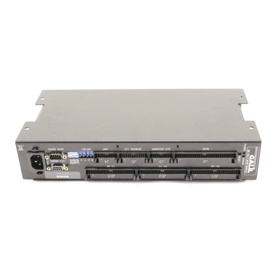
Page 160: Card Level Layout
Card Level Layout 148 • Appendices DMC-1500... -
Page 161: Connectors For Dmc-1500 Main Board
Connectors for DMC-1500 Main Board J2 - Main (60 pin IDC) 1 Ground 2 5 Volts 3 Error 4 Reset 5 Limit Common (LSCOM) 6 Forward Limit - X 7 Reverse Limit - X 8 Home - X 9 Forward Limit - Y 10 Reverse Limit - Y 11 Home - Y 12 Forward Limit - Z... -
Page 162: J5 - General I/O (26 Pin Idc)
J5 - General I/O (26 pin IDC) 1 Analog 1 2 Analog 2 3 Analog 3 4 Analog 4 5 Analog 5 6 Analog 6 7 Analog 7 8 Ground 9 5 Volts 10 Output 1 11 Output 2 12 Output 3 13 Output 4 14 Output 5 15 Output 6... -
Page 163: J4 - Driver (20 Pin Idc)
17 Amp enable W 18 PWM W/STEP W 19 Sign W/DIR W 20 Ground J6 - Daughter Board Connector (60 pin ) For use only with a Galil daughter board. J7 - 10 pin For test only. Appendices • 151 DMC-1500... -
Page 164: Connectors For Auxiliary Board (Axes E,F,G,H)
Connectors for Auxiliary Board (Axes E,F,G,H) JD2 - Main (60 pin IDC) 1 Ground 2 5 Volts 3 N.C. 4 N.C. 5 Limit Common 6 Forward Limit - E 7 Reverse Limit - E 8 Home - E 9 Forward Limit - F 10 Reverse Limit - F 11 Home F 12 Forward Limit - G... -
Page 165: Jd5 - I/O (26 Pin Idc)
JD5 - I/O (26 pin IDC) 1 Input 17 (TTL) 2 Input 18 (TTL) 3 Input 19 (TTL) 4 Input 20 (TTL) 5 Input 21 (TTL) 6 Input 22 (TTL) 7 Input 23 (TTL) 8 Ground 9 5 Volts 10 Output 9 11 Output 10 12 Output 11 13 Output 12... -
Page 166: Jd4 - 20 Pin Idc - Amplifiers
JD4 - 20 pin IDC - Amplifiers 1 Motor Command E 2 Amp enable E 3 PWM E/Step E 4 Sign E/Dir E 5 NC 6 Motor Command F 7 Amp enable F 8 PWM F/Step F 9 Sign F/Dir F 10 NC 11 Motor Command G 12 Amp enable G... -
Page 167: Dmc-1500 Serial Cable Specifications
+Receive Current Loop Data Data Terminal Ready Ring Indicator -Receive Current Loop Return 9 Pin Serial Connector Table describes the pinout for standard serial ports found on most computers. PIN NUMBER FUNCTION Carrier Detect Receive Data Transmit Data Data Terminal Ready Signal Ground Data Set Ready Request to Send... - Page 168 Computer 9 pin to DMC-1500 Main Port Cable (9 pin) 9 PIN (FEMALE - COMPUTER) 9 PIN (FEMALE - CONTROLLER) 1 (Carrier Detect) 2 (Receive Data) 3 (Transmit Data) 4 (Data Terminal Ready) 5 (Signal Ground) Controller Ground Computer 25 pin to DMC-1500 Auxiliary Port Cable (9 pin) 25 PIN (MALE - TERMINAL) 9 PIN (MALE - CONTROLLER) 20 (Data Terminal Ready)
-
Page 169: Pin-Out Description For Dmc-1500
Pin-Out Description for DMC-1500 Outputs Analog Motor Command +/- 10 Volt range signal for driving amplifier. In servo mode, motor command output is updated at the controller sample rate. In the motor off mode, this output is held at the OF command level. Amp Enable Signal to disable and enable an amplifier. - Page 170 Inputs Encoder, A+, B+ Position feedback from incremental encoder with two channels in quadrature, CHA and CHB. The encoder may be analog or TTL. Any resolution encoder may be used as long as the maximum frequency does not exceed 8,000,000 quadrature states/sec. The controller performs quadrature decoding of the encoder signals resulting in a resolution of quadrature counts (4 x encoder cycles).
-
Page 171: Configuration Description For Dmc-1500
Configuration Description for DMC-1500 Jumpers LABEL FUNCTION (IF JUMPERED) For each axis, the SM jumper selects the SM magnitude mode for servo motors or selects stepper motors. If you are using a stepper motor for an axis, you must jumper SM for that axis. The analog motor command is not valid with SM jumpered. -
Page 172: Adjustment Pots
Z offset Used to null ACMD offset for Z axis W offset Used to null ACMD offset for W axis Note: These adjustments are made at the Galil factory and should need adjustment under most applications. 160 • Appendices DMC-1500... -
Page 173: Accessories And Options
Accessories and Options DMC-1510 Single Axis Controller DMC-1520 Two-Axis Controller DMC-1530 Three-Axis Controller DMC-1540 Four-Axis Controller DMC-1550 Five-Axis Controller DMC-1560 Six-Axis Controller DMC-1570 Seven-Axis Controller DMC-1580 Eight-Axis Controller 16 Bit ADC Option ICM-1100* Interface board AMP-1110 Single axis amplifier AMP-1120... -
Page 174: Icm-1100 Interconnect Module
ICM-1100 Interconnect Module The ICM-1100 Interconnect Module provides easy connections between the DMC-1500 series controllers and other system elements, such as amplifiers, encoders, and external switches. The ICM- 1100 accepts each DMC-1500 ribbon cable (for J2, J3, J4 and J5) and breaks them into screw-type terminals. - Page 175 Rev A + B Rev C Label Description Terminal # Terminal # DIRW W direction for stepper Analog Input 1 Analog Input 2 Analog Input 3 Analog Input 4 Analog Input 5 Analog Input 6 Analog Input 7 Ground OUT1 Digital Output 1 OUT2 Digital Output 2...
- Page 176 XAB+ X Auxiliary encoder B+ Rev A + B Rev C Label Description Terminal # Terminal # XAA- X Auxiliary encoder A- XAA+ X Auxiliary encoder A+ Ground 5 Volts LSCOM Limit common FLSX X Forward limit RLSX X Reverse limit HOMEX X Home Input FLSY...
-
Page 177: J2 - Main (60 Pin Idc)
9 INDEX - 10 INDEX *CAUTION: The ICM-1100 10-pin connectors are designed for the N23 and N34 encoders from Galil. If you are using Galil's Motor-5-500, Motor-50-1000 or Motor-500-1000, you must cut encoder wires 5, 6, 7 and 9. Appendices • 165... -
Page 178: Icm-1100 Drawing
ICM-1100 Drawing 1 3 . 4 0 " 1 . 0 0 " 0 . 7 0 " 1 . 0 1 " 0 . 7 0 " 0 . 4 5 " 1 . 0 0 " 0 . 4 4 " 3 . -
Page 179: Amp-11X0 Mating Power Amplifiers
Gain 1 amp/volt TERM-1500 Operator Terminal Two types of terminals are offered from Galil; the handheld unit and the panel mount unit. Both have the same programming characteristics. Hand held unit is shown in the in the following: Appendices • 167... - Page 180 168 • Appendices DMC-1500...
- Page 181 The panel mount terminal is shown following: Features - For easy data entry to DMC-1500 motion controller - 4 line x 20 character Liquid Crystal Display - Full numeric keypad - Five programmable function keys - Available in Hand-held or Panel Mount - No external power supply required - Connects directly to RS232 port P2 via coiled cable Description...
- Page 182 Keypad Maps - Hand-Held 30 Keys: 5 keys across, 6 down Single Key Output F1 (22) F2 (23) F3 (24) F4 (25) F5 (26) CTRL SHIFT SPACE BKSPC ENTER Shift Key Output CTRL SHIFT CTRL Key Output (18) (16) (17) (19) "...
- Page 183 Keypad Map - Panel Mount -- 6 columns x 5 rows Single Key Output CTRL SHIFT SPACE BKSPC ENTER Shift Key Output CTRL SHIFT CTRL Key Output (18) (19) " (16) < > (17) CTRL SHIFT Note: Values in parentheses are ASCII decimal values. Key locations are represented by [m,n] where m is element column, n is element row.
- Page 184 Example: MG {P2}{^27},"H" Sends escape H to the terminal from port 2 Cursor Movement Commands ESC A Cursor Up ESC B Cursor Down ESC C Cursor Right ESC D Cursor Left Erasing Display ESC E Clear Display and Home ESC I Clear Display ESC J Cursor to End of Display...
- Page 185 In the above sequence, Pr is the row number and Pc is the column number of the target cursor location. These parameters are formed by adding hexadecimal 1F to the row and column numbers. Row and column numbers are absolute, with row 1, column 1 (Pr = H20, Pc = H20) representing the upper left corner of the display.
- Page 186 When using Port 2, use CC command to configure P2. Use male adapter. Example: CC 9600,0,0,1 Configures P2 MG{P2} "Hello There", V1{F2.1} Send message to P2 IN{P2} "Enter Value", NUM Prompts operator for value Example: CI 0,2,1;CC 9600,0,0,1 #A Interrupt on any key; Configure P2 MG {P2} "press F1 to start X"...
-
Page 187: Db-15072 Opto-22 Expansion Option
5. Ground 6. CTS - input 7. RTS - output 8. CTS - input 9. 5V or no connect or sample clock with jumpers NOTE: Out and in are referenced to the terminal. Ordering Information TERM-1500H-P2 Hand-held, female adapter TERM-1500P-P2 Panel Mount, female adapter DB-15072 OPTO-22 Expansion Option The DB-15072 is a version of the DMC-1500 that provides an interface to up to 72 OPTO 22 I/O modules. -
Page 188: Connector Description Of The Db-15072
Accessing the I/O of the DB-15072 The command, OP, may be used to set the state of output bits. The OP command has 2 parameters. The first parameter sets the values of the main output port of the controller (On a DB-15072 controller, this parameter would address outputs 1-8). - Page 189 JD1 Pinout Block Bit No. SBn,@IN[n] Signal Ground Ground Ground Ground Ground Ground Ground Ground Ground Ground Ground Ground Ground Ground Ground Ground Ground Ground Ground Ground Ground Ground Ground Ground 5 volts Ground JD2 Pinout (Note: All points are inputs on this cable) Block Bit No.
- Page 190 Block Bit No. SBn,@IN[n] Ground Ground Ground Ground Ground Ground Ground Ground Ground Ground Ground 5 volts Ground JD3 Pinout (Note: All points are inputs on this cable): Block Bit No. @IN[n] Ground Ground Ground Ground Ground Ground Ground Ground Ground Ground Ground...
-
Page 191: Coordinated Motion - Mathematical Analysis
Coordinated Motion - Mathematical Analysis The terms of coordinated motion are best explained in terms of the vector motion. The vector velocity, Vs, which is also known as the feed rate, is the vector sum of the velocities along the X and Y axes, Vx and Vy. - Page 192 The first line describes the straight line vector segment between points A and B. The next segment is a circular arc, which starts at an angle of 180° and traverses -90°. Finally, the third line describes the linear segment between points C and D. Note that the total length of the motion consists of the segments: Linear 10000 units...
- Page 193 The acceleration time, T a , is given by 100000 0 05 2000000 The slew time, Ts, is given by 35708 − − 0 05 0 307 100000 The total motion time, Tt, is given by = 0 407 The velocities along the X and Y axes are such that the direction of motion follows the specified path, yet the vector velocity fits the vector speed and acceleration requirements.
-
Page 194: Dmc-700/Dmc-1500 Comparison
time Figure 12.4 - Vector and Axes Velocities DMC-700/DMC-1500 Comparison Modes of Motion DMC-700 DMC-1500 Relative positioning Absolute positioning Velocity control Linear interpolation Up to 4 axes Up to 8 axes Circular interpolation Any 2 axes plus 3rd tangent Any 2 axes plus 3rd tangent Maximum number of segments in motion Infinite, continuous vector feed path... - Page 195 Specifications DMC-700 DMC-1500 2 x 10 6 counts/s 8 x 10 6 counts/s Maximum encoder frequency DAC resolution 12-bits 14-bits or 16-bits 8 x 10 6 2 x 10 9 Maximum move length Sample time 1 msec 0.5 msec (4 axes) Program memory 500 lines, 32 char 1000 lines, 80 char...
-
Page 196: List Of Other Publications
"Step by Step Design of Motion Control Systems" by Dr. Jacob Tal "Motion Control Applications" by Dr. Jacob Tal "Motion Control by Microprocessors" by Dr. Jacob Tal Contacting Us Galil Motion Control 3750 Atherton Road Rocklin, CA 95765 Phone: 916-626-0101 Fax: 916-626-0102 Internet address: support@galilmc.com URL: www.galilmc.com 184 •... -
Page 197: Warranty
The warranty period for controller boards is 1 year. The warranty period for all other products is 180 days. In the event of any defects in materials or workmanship, Galil Motion Control will, at its sole option, repair or replace the defective product covered by this warranty without charge. To obtain warranty... - Page 198 THIS PAGE LEFT BLANK INTENTIONALLY 186 • Appendices DMC-1500...
- Page 199 Bypassing Optoisolation 29 Capture Data Index Record 64, 67, 106, 109, 110 Circle 124 Circular Interpolation 1, 24, 50–53, 55, 108, 124 Clear Bit 119 Clear Sequence 45, 47, 51, 53 Clock 106 CMDERR 84, 98, 100 Command Syntax 37–38 Command Summary 40, 106, 108 Commanded Position 42–43, 55–56, 100, 108, 122, 137–39...
- Page 200 Digital Filter 144–45, 147–49 PID 14, 140, 144, 149 Tuning 1 Proportional Gain 140 Digital Input 25, 27, 103, 120 Stability 71, 127, 133–34 Digital Output 103, 119 Find Edge 26, 75 Clear Bit 119 Formatting 114, 115–18 Dip Switch Frequency 5, 146–48 Address 165, 166–67, 188 Function 26–27, 101–7, 124, 126...
- Page 201 Analog 103–5, 106, 114, 121–22, 126 Logical Operators 111 Digital 103, 120 Input Interrupt 84, 92, 98–99, 120–21 ININT 84, 98–99, 120–21 Masking Input of Data 110 Bit-Wise 95, 101 Inputs 1 Math Function Analog 25, 31, 151, 167 Absolute Value 96, 103, 130 Analog Inputs 1 Bit-Wise 95, 101 Encoder Input 1...
- Page 202 Home Input 26, 75, 106 Output Amplifier Enable 31–32, 129 Set Bit 119 ICM-1100 12, 25, 29, 30 Scaling Interconnect Module 7–8 Ellipse Scale 53 Motor Command 14, 21, 32, 144 S-Curve Output of Data 113 Motion Smoothing 1, 74 Clear Bit 119 SDK 81 Set Bit 119...
-
Page 203: Index • 195
Tell Position 36, 92, 105–7 Term-1500 33 Terminal 26, 29, 81, 104, 115 Theory 137 Damping 134, 140 Digital Filter 144–45, 147–49 Modeling 137, 140–41, 145 PID 14, 140, 144, 149 Stability 71, 127, 133–34, 140, 146 TIME 106–7 Clock 106 Time Interval 63–64, 67, 108 Timeout 10, 84, 91, 98, 99 MCTIME 84, 91, 98, 100...
Need help?
Do you have a question about the DMC-1510 and is the answer not in the manual?
Questions and answers