Table of Contents
Advertisement
Quick Links
Advertisement
Table of Contents

Related Manuals for Galil DMC-4040


Summary of Contents for Galil DMC-4040
- Page 1 USER MANUAL DMC-40x0 Manual Rev. 1.0f By Galil Motion Control, Inc. Galil Motion Control, Inc. 270 Technology Way Rocklin, California 95765 Phone: (916) 626-0101 Fax: (916) 626-0102 E-mail Address: support@galilmc.com URL: www.galilmc.com Rev 8/09...
- Page 2 Attention: Pertains to controllers with more than 4 axes. 4080 Please note that many examples are written for the DMC-4040 four-axes controller or the DMC-4080 eight axes controller. Users of the DMC-4030 3-axis controller, DMC-4020 2-axes controller or DMC-4010 1-axis controller should note that the DMC-4030 uses the axes denoted as XYZ, the DMC-4020 uses the axes denoted as XY, and the DMC-4010 uses the X-axis only.
-
Page 3: Table Of Contents
Step 3. Install the Communications Software ......14 Step 4. Connect 20-80VDC Power to the Controller ....15 Step 5. Establish Communications with Galil Software ... 15 Step 6. Determine the Axes to be Used for Sinusoidal Commutation ............17 Step 7. - Page 4 Example 3 - Multiple Axes ............26 Example 4 - Independent Moves ..........26 Example 5 - Position Interrogation ........... 26 Example 6 - Absolute Position ..........26 Example 7 - Velocity Control ........... 27 Example 8 - Operation Under Torque Limit ......27 Example 9 - Interrogation ............
- Page 5 GalilTools Communication Libraries ........65 ActiveX Toolkit ................ 66 DMCWin Programmers Toolkit ..........66 Galil Communications API with C/C++ ........67 Galil Communications API with Visual Basic ......67 DOS, and QNX tools ....................69 Chapter 5 Command Basics Introduction ........................70 Command Syntax - ASCII ....................
- Page 6 Multi-Axis Coordinated Move ..........108 Contour Mode ....................... 110 Specifying Contour Segments ........... 110 Additional Commands .............. 111 Command Summary - Contour Mode ........111 Stepper Motor Operation ....................115 Specifying Stepper Motor Operation ........115 Using an Encoder with Stepper Motors ........116 Command Summary - Stepper Motor Operation .....
- Page 7 Interrogation Commands ............162 Formatting Variables and Array Elements ....... 163 Converting to User Units ............164 Hardware I/O ........................ 164 Digital Outputs ................164 Digital Inputs ................165 The Auxiliary Encoder Inputs ........... 166 Input Interrupt Function ............166 Analog Inputs ................
- Page 8 Pin-Out Description for DMC-40x0 ................208 Configuring the Amplifier Enable Circuit ..............210 ICM-42000 and ICM-42100 ............. 210 DMC-4040 (Steps 1 and 2) ............210 DMC-4080 (Steps 1 and 2) ............212 DMC-4040 and DMC-4080 (Step 3) ........214 DMC-4040 (Steps 4 and 5) ............221 DMC-4080 (Steps 4 and 5) ............
- Page 9 Low Current Setting (LC Command) ........247 Step Drive Resolution Setting (YA command) ......247 ELO Input ................. 248 A4 – SDM-44140 (-D4140) Description ........................249 Electrical Specifications ....................250 Mating Connectors ..............250 Operation ........................251 Current Level Setup (AG Command) ........251 Low Current Setting (LC Command) ........
-
Page 10: Chapter 1 Overview
The DMC-40x0 is available with up to eight axes in a single stand alone unit. The DMC-4010, 4020, 4030, 4040 are one thru four axes controllers and the DMC-4050, 4060, 4070, 4080 are five thru eight axes controllers. All eight axes have the ability to use Galil’s integrated amplifiers or drivers and connections for integrating external devices. -
Page 11: Overview Of Motor Types
Chapter 2 describes the proper connection and procedure for using stepper motors. If encoders are available on the stepper motor, Galil’s Stepper Position Maintenance Mode may be used for automatic monitoring and correction of the stepper position. See Stepper Position Maintenance Mode (SPM) in Chapter 6 for more information. -
Page 12: Overview Of External Amplifiers
Overview of Galil Amplifiers and Drivers With the DMC-40x0 Galil offers a variety of Servo Amplifiers and Stepper Drivers that are integrated into the same enclosure as the controller. Using the Galil Amplifiers and Drivers provides a simple straightforward motion control solution in one box. -
Page 13: Dmc-40X0 Functional Elements
Motor Interface Galil’s GL-1800 custom, sub-micron gate array performs quadrature decoding of each encoder at up to 12 MHz. For standard servo operation, the controller generates a +/-10 volt analog signal (16 Bit DAC). For sinusoidal commutation operation, the controller uses two DACs to generate two +/-10 volt analog signals. For stepper motor operation, the controller generates a step and direction signal. -
Page 14: System Elements
Motor A motor converts current into torque which produces motion. Each axis of motion requires a motor sized properly to move the load at the required speed and acceleration. (Galil’s MotorSizer Web tool can help you with motor sizing: w ww.galilmc.com/support/motorsizer 3 3 2 H The motor may be a step or servo motor and can be brush-type or brushless, rotary or linear. -
Page 15: Encoder
AF in the command reference. To interface with other types of position sensors such as absolute encoders, Galil can customize the controller and command set. Please contact Galil to talk to one of our applications engineers about your particular system requirements. -
Page 16: Chapter 2 Getting Started
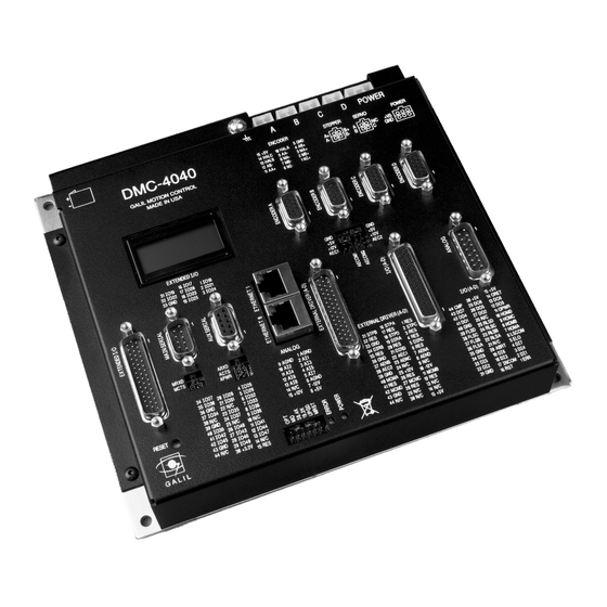
DMC-4040 Layout The following layouts assume either an ICM-42000(I000) or ICM-42100(I100) interconnect modules are installed. For layouts of systems with ICM-42200’s(I200) installed please contact Galil. Overall dimensions and footprint are identical, the only differences are in connector type and location. -
Page 17: Dmc-4080 Layout
DMC-4080 Layout Figure 2-2 - Outline of the of the DMC-4080 Chapter 2 Getting Started • 8 DMC-40x0 User Manual... -
Page 18: Dmc-40X0 Power Connections
Figure 2-3 – Connector locations for the DMC-40x0 Figure 2-4 – Power Connector used when controller is ordered without Galil Amplifiers *See Power connector information for specific amplifiers in the Integrated section of the Appendices. For more information on Connectors (mfg PN’s and diagrams) see the Power Connector Section in the Appendix. -
Page 19: Dmc-4040 Dimensions
DMC-4040 Dimensions Figure 2-5 – Dimensions of DMC-4040 Chapter 2 Getting Started • 10 DMC-40x0 User Manual... -
Page 20: Dmc-4080 Dimensions
DMC-4080 Dimensions Figure 2-6 Dimensions of DMC-4080 Chapter 2 Getting Started • 11 DMC-40x0 User Manual... -
Page 21: Elements You Need
Elements You Need For a complete system, Galil recommends the following elements: DMC-4010, 4020, 4030, or DMC-4040 Motion Controller DMC-4050, 4060, 4070 or DMC-4080 Motor Amplifiers (Integrated when using Galil amplifiers and drivers) Power Supply for Amplifiers and controller Brush or Brushless Servo motors with Optical Encoders or stepper motors. -
Page 22: Installing The Dmc-40X0
The second DAC for the sinusoidal signal will be the highest available DAC on the controller. For example: Using a DMC-4040, the command BAA will configure the A axis to be the main sinusoidal signal and the 'D' axis to be the second sinusoidal signal. -
Page 23: Step 2. Install Jumpers On The Dmc-40X0
EEPROM. EEPROM corruption should never occur, however, it is possible if there is a power fault during a firmware update. If EEPROM corruption occurs, your controller may not operate properly. In this case, install the UPGRD Jumper and use the update firmware function on the Galil Terminal to re-load the system firmware. -
Page 24: Step 4. Connect 20-80Vdc Power To The Controller
Step 4. Connect 20-80VDC Power to the Controller If the controller was ordered with Galil Amplifiers or Drivers, then power to the controller will be supplied through those power connectors. Otherwise the power will come through the connector on the side of the controller. See DMC-40x0 Power Connections. - Page 25 WSDK or under the “Tools” menu in the Galil Smart Terminal. Use the “New Controller” button to add a new entry to the Registry. You will need to supply the Galil Controller model (eg: DMC-40x0). Pressing the down arrow to the right of this field will reveal a menu of valid controller types.
-
Page 26: Step 6. Determine The Axes To Be Used For Sinusoidal Commutation
Please note that the serial port on the controller must be set for handshake mode for proper communication with Galil software. The user must also insure that a “straight-through” serial cable is being used (NOT a Null Modem cable), see appendix for pin-out of serial cable. -
Page 27: Step 7. Make Connections To Amplifier And Encoder
C axis will be the motor command G signal. Step 7. Make Connections to Amplifier and Encoder. If the system is run solely by Galil’s integrated amplifiers or drivers, skip this section, the amplifier is already connected to the controller. -
Page 28: Step 8A. Connect Standard Servo Motors
When ordered with ICM-42000’s or ICM-42100’s the AEN signal is configurable for axes 1-4 and axes 5-8. 4080 Ex – axes 1-4 could be ordered as 5V high amp enable, and axes 5-8 could be ordered as 12V low amp enable. - Page 29 10 volt signal generates the maximum required current. In the velocity mode, a command signal of 10 volts should run the motor at the maximum required speed. For Galil amplifiers, see Integrated . Step A. Check the Polarity of the Feedback Loop It is assumed that the motor and amplifier are connected together and that the encoder is operating correct (Step 7).
-
Page 30: Step 8B. Connect Sinusoidal Commutation Motors
Inverting the Loop Polarity When the polarity of the feedback is incorrect, the user must invert the loop polarity and this may be accomplished by several methods. If you are driving a brush-type DC motor, the simplest way is to invert the two motor wires (typically red and black). - Page 31 NOTE: When using Galil Windows software, the timeout must be set to a minimum of 10 seconds (time-out = 10000) when executing the BS command. This allows the software to retrieve all messages returned from the controller.
- Page 32 reset of the controller. If no Hall sensors are used, the controller will not be able to make this estimate and the commutation phase must be set before enabling the motor. To initialize the commutation without Hall effect sensor use the command, BZ. This function drives the motor to a position where the commutation phase is zero, and sets the phase to zero.
-
Page 33: Step 8C. Connect Step Motors
PID filter does not function and the position error is not generated. To connect step motors with the DMC-40x0 you must follow this procedure – If you have a Galil integrated stepper driver skip Step A, the step and direction lines are already connected to the driver: Step A. -
Page 34: Design Examples
Next you need to increase the value of KP gradually (maximum allowed is 1023.875). You can monitor the improvement in the response with the Tell Error instruction Proportion gain KP 10 <return> Tell error TE A <return> As the proportional gain is increased, the error decreases. Again, the system may vibrate if the gain is too high. -
Page 35: Example 3 - Multiple Axes
SP20000 Speed DC 100000 Deceleration AC 100000 Acceleration BG A Start Motion Example 3 - Multiple Axes Objective: Move the four axes independently. Instruction Interpretation PR 500,1000,600,-400 Distances of A,B,C,D SP 10000,12000,20000,10000 Slew speeds of A,B,C,D AC 10000,10000,10000,10000 Accelerations of A,B,C,D DC 80000,40000,30000,50000 Decelerations of A,B,C,D BG AC... -
Page 36: Example 7 - Velocity Control
DP 0,2000 Define the current positions of A,B as 0 and 2000 PA 7000,4000 Sets the desired absolute positions BG A Start A motion BG B Start B motion After both motions are complete, the A and B axes can be command back to zero: PA 0,0 Move to 0,0 BG AB... -
Page 37: Example 10 - Operation In The Buffer Mode
Start the program running If the ED command is issued from the Galil Windows terminal software (such as SmartTERM), the software will open a Windows based editor. From this editor a program can be entered, edited, downloaded and uploaded to the controller. -
Page 38: Example 13 - Motion Programs With Trippoints
WT 500 Wait 500 ms TP A Tell position A V1=V1+1000 Increase the value of V1 JP #LOOP,V1<10001 Repeat if V1<10001 After the above program is entered, quit the Editor Mode, <cntrl>Q. To start the motion, command: XQ #A Execute Program #A Example 13 - Motion Programs with Trippoints The motion programs may include trippoints as shown below. -
Page 39: Example 15 - Linear Interpolation
End of Program To start the program, command XQ #A Execute Program #A This program moves A to an initial position of 1000 and returns it to zero on increments of half the distance. Note, _TPA is an internal variable which returns the value of the A position. Internal variables may be created by preceding a DMC-40x0 instruction with an underscore, _. - Page 40 (-4000,4000) (0,4000) R=2000 (-4000,0) (0,0) local zero Figure 2-7 Motion Path for Circular Interpolation Example Chapter 2 Getting Started • 31 DMC-40x0 User Manual...
-
Page 41: Chapter 3 Connecting Hardware
Chapter 3 Connecting Hardware Overview The DMC-40x0 provides opto-isolated digital inputs for forward limit, reverse limit, home, and abort signals. The controller also has 8 opto-isolated, uncommitted inputs (for general use) as well as 8 high power opto- isolated outputs and 8 analog inputs configured for voltages between +/- 10 volts. Controllers with 5 or more axes have an additional 8 opto-isolated inputs and an additional 8 high 4080 power opto-isolated outputs. -
Page 42: Home Switch Input
Home Switch Input Homing inputs are designed to provide mechanical reference points for a motion control application. A transition in the state of a Home input alerts the controller that a particular reference point has been reached by a moving part in the motion control system. -
Page 43: Elo (Electronic Lock-Out) Input
Connecting the isolated ground to INCOM will configure the inputs for active high. If there is not an isolated available, the Galil 5V or 12V and GND may be used. It is recommended to use an isolated supply for the optoisolated inputs. - Page 44 The ELO, ABRT and RST pins are found on the I/O (A-D) D-Sub and are duplicated on the I/O (E-H) 4080 D-Sub. I.e. There is only one ELO, ABRT and RST input for an 8 axis controller. The common is the INCOM found on the I/O (A-D) D-Sub connector.
-
Page 45: Using An Isolated Power Supply
LSCOM Additional Limit 2.2kΩ Switches (Dependent on RPACK Number of Axes) FLSX RLSX HOMEX FLSY RLSY HOMY INCOM 2.2kΩ RPACK ABRT YLATCH ZLATCH WLATCH XLATCH Figure 3-1: The Optoisolated Inputs. Using an Isolated Power Supply To take full advantage of opto-isolation, an isolated power supply should be used to provide the voltage at the input common connection. -
Page 46: Bypassing The Opto-Isolation
External Resistor Needed for External Resistor Needed for Voltages > 28V Voltages > 28V LSCOM LSCOM 2.2K 2.2K FLSX FLSX Configuration to source current at the Configuration to sink current at the LSCOM terminal and sink current at LSCOM terminal and source current at switch inputs switch inputs Figure 3-2. -
Page 47: High Power Opto-Isolated Outputs
High Power Opto-Isolated Outputs The DMC-40x0 has different interconnect module options, this section will describe the 500mA optically isolated outputs that are used on the ICM-42x00. Electrical Specifications Output Common Max Voltage 30 VDC Output Common Min Voltage 12 VDC Max Drive Current per Output 0.5 A (not to exceed 3A for all 8 outputs) Wiring the Opto-Isolated Outputs... -
Page 48: Analog Inputs
Analog Inputs The DMC-40x0 has eight analog inputs configured for the range between -10V and 10V. The inputs are decoded by a 12-bit A/D decoder giving a voltage resolution of approximately .005V. A 16-bit ADC is available as an option (Ex. -
Page 49: Extended I/O Of The Dmc-40X0 Controller
Extended I/O of the DMC-40x0 Controller The DMC-40x0 controller offers 32 extended TTL I/O points which can be configured as inputs or outputs in 8 bit increments. Configuration is accomplished with command CO – see Extended I/O of the DMC-40x0 Controller The I/O points are accessed through the 44 pin D-Sub connector labeled EXTENDED I/O. -
Page 50: Amplifier Interface
If your amplifier requires a different configuration than the default 5V HAEN sinking it is highly recommended that the DMC-40x0 is ordered with the desired configuration. See the DMC-40x0 ordering information in the catalog ( ) or contact Galil for more information on ordering http://www.galilmc.com/catalog/cat40x0.pdf different configurations. - Page 51 Amplifier Enable Circuit Sinking Output Configuration (Pin 1 of LTV8441 in Pin 2 of Socket U4) Socket U4 TTL level Amp Enable signal AECOM2 from controller Pin 1 Amp Enable Output to Drive (SH = 5V, MO = 0V) of socket (AENn) RP2 (470 Ohm) RP6 (820 Ohm)
- Page 52 Amplifier Enable Circuit Sourcing Output Configuration (Pin 1 of LTV8441 in Pin 1 of Socket U4) Socket U4 TTL level Amp Enable signal AECOM2 from controller Pin 1 Pin 1 Amp Enable Output to Drive (SH = 5V, MO = 0V) of socket (AENn) RP2 (470 Ohm)
-
Page 53: Icm-42200 Amplifier Enable Circuit
ICM-42200 Amplifier Enable Circuit This section describes how to configure the ICM-42200 for different Amplifier Enable outputs. The ICM-42200 is designed to be used with external amplifiers. As a result, the amplifier enable circuit for each axis is individually configurable through jumper settings. The user can choose between High-Amp-Enable (HAEN), Low-Amp-Enable (LAEN), 5V logic, 12V logic, external voltage supplies up to 24V, sinking, or sourcing. - Page 54 Chapter 3 Connecting Hardware • 45 DMC-40x0 User Manual...
- Page 55 Chapter 3 Connecting Hardware • 46 DMC-40x0 User Manual...
- Page 56 Chapter 3 Connecting Hardware • 47 DMC-40x0 User Manual...
-
Page 57: Chapter 4 Software Tools And Communication
The following sections in this chapter are a description of the communications protocol, and a brief introduction to the software tools and communication techniques used by Galil. At the application level, GalilTools is the basic programs that the majority of users will need to communicate with the controller, to perform basic setup, and to develop application code (.DMC programs) that is downloaded to the controller. - Page 58 RS232 - Main Port {P1} DATATERM 1 No Connect 6 No Connect 2 Transmit Data - output 7 Clear To Send - input 3 Receive Data - input 8 Request To Send - output 4 No Connect 9 No connect 5 Ground RS232 - Auxiliary Port {P2} DATASET 1 No Connect...
-
Page 59: Configuration
Example: CC 19200,0,1,1 Configure auxiliary communication port for 19200 baud, no handshake, general port mode and echo turned on. RS-422 Configuration The DMC-40x0 can be ordered with the main and/or auxiliary port configured for RS-422 communication. RS-422 communication is a differentially driven serial communication protocol that should be used when long distance serial communication is required in an application. -
Page 60: Addressing
The second method to assign an IP address is to use the BOOT-P utility via the Ethernet connection. The BOOT-P functionality is only enabled when DH is set to 0. Either a BOOT-P server on the internal network or the Galil software may be used. -
Page 61: Communicating With Multiple Devices
The third level of Ethernet addressing is the UDP or TCP port number. The Galil board does not require a specific port number. The port number is established by the client or master each time it connects to the DMC-40x0 board. -
Page 62: Modbus
Command Reference. The third level of Modbus communication uses standard Galil commands. Once the slave has been configured, the commands that may be used are @IN[], @AN[], SB, CB, OB, and AO. For example, AO 2020,8.2 would tell I/O number 2020 to output 8.2 volts. -
Page 63: Modbus Examples
Modbus Examples Example #1 DMC-4040 connected as a Modbus master to a RIO-47120 via Modbus. The DMC-4040 will set or clear all 16 of the RIO’s digital outputs Begin by opening a connection to the RIO which in our example has IP address 192.168.1.120 (Issued to DMC-4040) IHB=192,168,1,120<502... -
Page 64: Data Record
Analog input 4 = 0xC0C33333 = -6.1V Example #3 DMC-4040 connected as a Modbus master to a hydraulic pump. The DMC-4040 will set the pump pressure by writing to an analog output on the pump located at Modbus address 30000 and consisting of 2 Modbus registers forming a 32 bit floating point value. - Page 65 Note: UB = Unsigned Byte (1), UW = Unsigned Word (2), SW = Signed Word (2), SL = Signed Long Word (4), UL = Unsigned Long Word (4) ADDR TYPE ITEM Byte of Header Byte of Header Byte of Header Byte of Header 04-05 sample number...
- Page 66 error code thread status – see bit field map below 52-55 (new) Amplifier Status 56-59 (new) Segment Count for Contour Mode 60-61 (new) Buffer space remaining – Contour Mode 62-63 segment count of coordinated move for S plane 64-65 coordinated move status for S plane – see bit field map below 66-69 distance traveled in coordinated move for S plane...
- Page 67 166-169 C axis position error 170-173 C axis auxiliary position 174-177 C axis velocity 178-181 (new size) C axis torque 182-183 SW or UW C axis analog input (new) C Hall Input Status Reserved 186-189 (new) C User defined variable (ZA) 190-191 D axis status –...
- Page 68 (new) F Hall Input Status Reserved 294-297 (new) F User defined variable (ZA) 298-299 G axis status – see bit field map below G axis switches – see bit field map below G axis stop code 302-305 G axis reference position 306-309 G axis motor position 310-313...
-
Page 69: Explanation Data Record Bit Fields
Explanation Data Record Bit Fields Header Information - Byte 0, 1 of Header: BIT 15 BIT 14 BIT 13 BIT 12 BIT 11 BIT 10 BIT 9 BIT 8 I Block T Block S Block Present Present Present in Data in Data in Data Record... -
Page 70: Notes Regarding Velocity And Torque Information
Axis Status (1 Word) BIT 15 BIT 14 BIT 13 BIT 12 BIT 11 BIT 10 BIT 9 BIT 8 Move in Mode of Mode of (FE) Home Phase Phase Mode of Progress Motion Motion Find (HM) in of HM of HM Motion PA or... -
Page 71: Unsolicited Messages Generated By Controller
The controller has a special command, CW, which can affect the format of unsolicited messages. This command is used by Galil Software to differentiate response from the command line and unsolicited messages. The command, CW1 causes the controller to set the high bit of ASCII characters to 1 of all unsolicited characters. This may cause characters to appear garbled to some terminals. -
Page 72: Galiltools (Windows And Linux)
GalilTools (Windows and Linux) GalilTools is Galil's set of software tools for current Galil controllers. It is highly recommended for all first-time purchases of Galil controllers as it provides easy set-up, tuning and analysis. GalilTools replaces the WSDK Tuning software with an improved user-interface, real-time scopes and communications utilities. - Page 73 Figure 4.1 - GalilTools Chapter 4 Software Tools and Communication • 64 DMC-40x0 User Manual...
-
Page 74: Creating Custom Software Interfaces
For Ethernet controllers, which support more than one connection, multiple objects may be used to communicate with the controller. An example of multiple objects is one Galil object containing a TCP handle to a DMC-40x0 for commands and responses, and one Galil object containing a UDP handle for unsolicited messages from the controller. -
Page 75: Activex Toolkit
Galil recommends the GalilTools Communication Library for all new applications. Galil's ActiveX Toolkit is useful for the programmer who wants to easily create a custom operator interface to a Galil controller. The ActiveX Toolkit includes a collection of ready-made ActiveX COM controls for use with Visual Basic, Visual C++, Delphi, LabVIEW and other ActiveX compatible programming tools. -
Page 76: Galil Communications Api With C/C
When programming in C/C++, the communications API can be used as included functions or through a class library. All Galil communications programs written in C must include the DMCCOM.H file and access the API functions through the declared routine calls. C++ programs can use the DMCCOM.H routines or use the class library defined in DMCWIN.H. - Page 77 This example code illustrates the use of DMCOpen() and DMCCommand(). A connection is made to controller #1 in the Galil registry upon launching the application. Then, the controller is sent the command ‘TPX’ whenever a command button is pressed. The response is then placed in a text box. When the application is closed, the controller is disconnected.
-
Page 78: Dos, And Qnx Tools
BASIC and C programs. Download DMCDOS at : h ttp://www.galilmc.com/support/download.html#dos 3 5 4 H Galil offers sample drivers for ISA and PCI cards for the QNX 4.24 operating system. We also offer drivers and utilities for QNX 6.2 for PCI only. Download at: h ttp://www.galilmc.com/support/download.html#linux... -
Page 79: Chapter 5 Command Basics
DMC-40x0 command interpreter. NOTE: If you are using a Galil terminal program, commands will not be processed until an <return> command is given. This allows the user to separate many commands on a single line and not begin execution until the user gives the <return>... -
Page 80: Coordinated Motion With More Than 1 Axis
PR 1000 Specify A only as 1000 PR ,2000 Specify B only as 2000 PR ,,3000 Specify C only as 3000 PR ,,,4000 Specify D only as 4000 PR 2000, 4000,6000, 8000 Specify A,B,C and D PR ,8000,,9000 Specify B and D only PR ?,?,?,? Request A,B,C,D values PR ,? -
Page 81: Command Syntax - Binary (Advanced)
One word (2 bytes per field) One long word (4 bytes) per field Galil real format (4 bytes integer and 2 bytes fraction) Byte 3 specifies whether the command applies to a coordinated move as follows: No coordinated motion movement Coordinated motion movement For example, the command STS designates motion to stop on a vector move, S coordinate system. -
Page 82: Binary Command Table
00 S is not active for PR 05 specifies bit 0 is active for A axis and bit 2 is active for C axis (2 03 E8 represents 1000 FE OC represents -500 Example The command ST XYZS would be : A1 00 01 07 where A1 is the command number for ST... -
Page 83: Controller Response To Data
reserved reserved reserved reserved reserved reserved reserved reserved reserved reserved reserved reserved reserved reserved reserved reserved reserved reserved reserved reserved reserved reserved reserved reserved reserved Controller Response to DATA The DMC-40x0 returns a : for valid commands and a ? for invalid commands. For example, if the command BG is sent in lower case, the DMC-40x0 will return a ?. -
Page 84: Summary Of Interrogation Commands
Summary of Interrogation Commands Report Command Position Report Latch ∧ ∧ Firmware Revision Information Stop Code Tell Status Tell Error Code Tell Dual Encoder Tell Error Tell Input Tell Position Trace Tell Switches Tell Torque Tell Velocity For example, the following example illustrates how to display the current position of the X axis: TP A <return>... -
Page 85: Chapter 6 Programming Motion
The DMC-4010 are single axis controllers and use X-axis motion only. Likewise, the DMC-4020 use X and Y, the DMC-4030 use X,Y, and Z, and the DMC-4040 use X,Y,Z, and W. The DMC-4050 use A,B,C,D, and E. The DMC-4060 use A,B,C,D,E, and F. The DMC-4070 use A,B,C,D,E,F, and G. The DMC-4080 use the axes A,B,C,D,E,F,G, and H. - Page 86 2-D motion path consisting of arc segments and linear Coordinated Motion segments, such as engraving or quilting. VS,VR VA,VD Third axis must remain tangent to 2-D motion path, such as Coordinated motion with tangent axis specified knife cutting. VS,VA,VD Electronic gearing where slave axes are scaled to master axis Electronic Gearing which can move in both directions.
-
Page 87: Independent Axis Positioning
Independent Axis Positioning In this mode, motion between the specified axes is independent, and each axis follows its own profile. The user specifies the desired absolute position (PA) or relative position (PR), slew speed (SP), acceleration ramp (AC), and deceleration ramp (DC), for each axis. On begin (BG), the DMC-40x0 profiler generates the corresponding trapezoidal or triangular velocity profile and position trajectory. - Page 88 _SPx Returns the speed for the axis specified by ‘x’ _PAx Returns current destination if ‘x’ axis is moving, otherwise returns the current commanded position if in a move. _PRx Returns current incremental distance specified for the ‘x’ axis Example - Absolute Position Movement PA 10000,20000 Specify absolute X,Y position AC 1000000,1000000...
-
Page 89: Independent Jogging
VELOCITY (COUNTS/SEC) X axis velocity profile 20000 Y axis velocity profile 15000 Z axis velocity profile 10000 5000 TIME (ms) Figure 6.1: Velocity Profiles of XYZ Notes on Figure 6.1: The X and Y axis have a ‘trapezoidal’ velocity profile, while the Z axis has a ‘triangular’ velocity profile. -
Page 90: Operand Summary - Independent Axis
Position Tracking The Galil controller may be placed in the position tracking mode to support changing the target of an absolute position move on the fly. New targets may be given in the same direction or the opposite direction of the current position target. - Page 91 To remain within a specified distance it would also need to constantly update the position target it is moving towards. Galil motion controllers support this type of motion with the position tracking mode. This mode will allow scheduled or random updates to the current position target on the fly. Based on the new target the controller will either continue in the direction it is heading, change the direction it is moving, or decelerate to a stop.
-
Page 92: Example - Motion 2
Figure 6.2: Position vs. Time (msec) Motion 1 Example - Motion 2: The previous step showed the plot if the motion continued all the way to 5000, however partway through the motion, the object that was being tracked changed direction, so the host program determined that the actual target position should be 2000 cts at that time. -
Page 93: Example Motion 4
Figure 6.4: Velocity vs. Time (msec) Motion 2 Example Motion 4 In this motion, the host program commands the controller to begin motion towards position 5000, changes the target to -2000, and then changes it again to 8000. Figure 6.5 shows the plot of position vs. time, Figure 6.6 plots velocity vs. -
Page 94: Trip Points
Figure 6.6: Velocity vs. Time Motion 4 Figure 6.7: Velocity cts/sec vs. Time (msec) with IT Note the controller treats the point where the velocity passes through zero as the end of one move, and the beginning of another move. IT is allowed, however it will introduce some time delay. Trip Points Most trip points are valid for use while in the position tracking mode. -
Page 95: Command Summary - Position Tracking Mode
Command Summary – Position Tracking Mode COMMAND DESCRIPTION AC n,n,n,n,n,n,n,n Acceleration settings for the specified axes AP n,n,n,n,n,n,n,n Trip point that holds up program execution until an absolute position has been reached DC n,n,n,n,n,n,n,n Deceleration settings for the specified axes MF n,n,n,n,n,n,n,n Trip point to hold up program execution until n number of counts have passed in the forward direction. - Page 96 Additional Commands The commands VS n, VA n, and VD n are used to specify the vector speed, acceleration and deceleration. The DMC-40x0 computes the vector speed based on the axes specified in the LM mode. For example, LM XYZ designates linear interpolation for the X,Y and Z axes.
-
Page 97: Command Summary - Linear Interpolation
LI 1000,1000 < 4000 Specify second linear segment with a vector speed of 4000 and end speed >1000 1000 LI 0,5000 < 4000 Specify third linear segment with a vector speed of 4000 and end speed 1000 >1000 End linear segments Begin motion sequence Program end Changing Feed Rate:... -
Page 98: Example - Linear Move
To illustrate the ability to interrogate the motion status, consider the first motion segment of our example, #LMOVE, where the X axis moves toward the point X=5000. Suppose that when X=3000, the controller is interrogated using the command ‘MG _AV’. The returned value will be 3000. The value of _CS, _VPX and _VPY will be zero. -
Page 99: Example - Multiple Moves
30000 27000 POSITION W 3000 4000 36000 40000 POSITION Z FEEDRATE TIME (sec) VELOCITY Z-AXIS TIME (sec) VELOCITY W-AXIS TIME (sec) Figure 6.8: Linear Interpolation Example - Multiple Moves This example makes a coordinated linear move in the XY plane. The Arrays VX and VY are used to store 750 incremental distances which are filled by the program #LOAD. -
Page 100: Vector Mode: Linear And Circular Interpolation Motion
Initialize position increment #LOOP LOOP VX [COUNT]=N Fill Array VX VY [COUNT]=N Fill Array VY N=N+10 Increment position COUNT=COUNT+1 Increment counter JP #LOOP,COUNT<750 Loop if array not full Label LM XY Specify linear mode for XY COUNT=0 Initialize array counter #LOOP2;JP#LOOP2,_LM=0 If sequence buffer full, wait JS#C,COUNT=500... -
Page 101: Additional Commands
This ‘local’ definition of zero does not affect the absolute coordinate system or subsequent coordinated motion sequences. The command, VP x,y specifies the coordinates of the end points of the vector movement with respect to the starting point. Non-sequential axis do not require comma delimitation. The command, CR r,q,d define a circular arc with a radius r, starting angle of q, and a traversed angle d. - Page 102 Compensating for Differences in Encoder Resolution: By default, the DMC-40x0 uses a scale factor of 1:1 for the encoder resolution when used in vector mode. If this is not the case, the command, ES can be used to scale the encoder counts. The ES command accepts two arguments which represent the number of counts for the two encoders used for vector motion.
-
Page 103: Command Summary - Coordinated Motion Sequence
Command Summary - Coordinated Motion Sequence COMMAND DESCRIPTION. VM m,n Specifies the axes for the planar motion where m and n represent the planar axes and p is the tangent axis. VP m,n Return coordinate of last point, where m=X,Y,Z or W. CR r,Θ, ±∆Θ... -
Page 104: Electronic Gearing
VP 0,3000 Segment CD CR 1500,90,-180 Segment DA End of sequence Begin Sequence The resulting motion starts at the point A and moves toward points B, C, D, A. Suppose that we interrogate the controller when the motion is halfway between the points A and B. The value of _AV is 2000 The value of _CS is 0 _VPX and _VPY contain the absolute coordinate of the point A... -
Page 105: Ramped Gearing
This can be a large shock to the system. For many applications it is acceptable to slowly ramp the engagement of gearing over a greater time frame. Galil allows the user to specify an interval of the master axis over which the gearing will be engaged. -
Page 106: Example - Electronic Gearing Over A Specified Interval
Figure 6.11: Velocity (cts/sec) vs. Time (msec) Ramped Gearing The slave axis for each figure is shown on the bottom portion of the figure; the master axis is shown on the top portion. The shock to the slave axis will be significantly less in Figure 6.11 than in Figure 6.10. The ramped gearing does have one consequence. -
Page 107: Command Summary - Electronic Gearing
Command Summary - Electronic Gearing COMMAND DESCRIPTION GA n Specifies master axes for gearing where: n = X,Y,Z or W or A,B,C,D,E,F,G,H for main encoder as master n = CX,CY,CZ, CW or CA, CB,CC,CD,CE,CF,CG,CH for commanded position. n = DX,DY,DZ or DW or DA, DB, DC, DD, DE, DF,DG,DH for auxiliary encoders n = S or T for gearing to coordinated motion. -
Page 108: Electronic Cam
GR,1 Set gear ratio for Y as 1:1 GM,1 Set gantry mode PR 3000 Command X motion BG X Start motion on X axis You may also perform profiled position corrections in the electronic gearing mode. Suppose, for example, that you need to advance the slave 10 counts. - Page 109 where x,y,z,w specify the cycle of the master and the total change of the slaves over one cycle. The cycle of the master is limited to 8,388,607 whereas the slave change per cycle is limited to 2,147,483,647. If the change is a negative number, the absolute value is specified. For the given example, the cycle of the master is 6000 counts and the change in the slave is 1500.
- Page 110 3000 2250 1500 2000 4000 6000 Master X Figure 6.12: Electronic Cam Example This disengages the slave axis at a specified master position. If the parameter is outside the master cycle, the stopping is instantaneous. To illustrate the complete process, consider the cam relationship described by the equation: Y = 0.5 * X + 100 sin (0.18 * X) where X is the master, with a cycle of 2000 counts.
- Page 111 INSTRUCTION INTERPRETATION #SETUP Label Select X as master EM 2000,1000 Cam cycles EP 20,0 Master position increments N = 0 Index #LOOP Loop to construct table from equation Note 3.6 = 0.18 * 20 P = N∗3.6 S = @SIN [P]*100 Define sine position Y = N*10+S Define slave position...
-
Page 112: Command Summary - Electronic Cam
Command Summary - Electronic CAM Command Description EA p Specifies master axes for electronic cam where: p = X,Y,Z or W or A,B,C,D,E,F,G,H for main encoder as master or M or N a for virtual axis master EB n Enables the ECAM EC n ECAM counter - sets the index into the ECAM table EG x,y,z,w... - Page 113 ET[9]=40,20 point in the ECAM table ET[10]=0,0 Starting point for next cycle EB 1 Enable ECAM mode JGZ=4000 Set Z to jog at 4000 EG 0,0 Engage both X and Y when Master = 0 Begin jog on Z axis #LOOP;JP#LOOP,V1=0 Loop until the variable is set EQ2000,2000...
-
Page 114: Pvt Mode
976us. This means that a “t” value of 1024 will yield one second of motion. The velocity value, “v” will always be in units of counts per second, regardless of the TM setting. PVT mode is not available in the “-FAST” version of the firmware. If this is required please consult Galil. Chapter 6 Programming Motion • 105... -
Page 115: Command Summary - Pvt
Command Summary – PVT COMMAND DESCRIPTION PVa = p,v,t Specifies the segment of axis 'a' for a incremental PVT segment of 'p' counts, an end speed of 'v' counts/sec in a total time of 't' samples. _PVa Contains the number of PV segments available in the PV buffer for a specified axes. Begin PVT mode _BTa Contaings the number PV segments that have executed... - Page 116 p(0 to .25) = 57 437.5 p(.25 to .5) = 151 p(.5 to .75) = 214 937.5 p(.75 to 1) = 245 1000 . 1 ( p(1 to 1.25) = 245 937.5 p(1.25 to 1.5) = 214 . 1 ( p(1.5 to 1.75) = 151 437.5 p(1.75 to 2) =57...
-
Page 117: Multi-Axis Coordinated Move
Actual Velocity and Position vs Time 1200 1400 1200 1000 1000 Velocity Position Time(Samples) Figure 6.15: Actual Velocity and Position vs Time of Parabolic Velocity Profile Multi-Axis Coordinated Move Many applications require moving two or more axes in a coordinated move yet still require smooth motion at the same time. - Page 118 The resultant DMC program is shown below. The position points are dictated by the application requirements and the velocities and times were chosen to create smooth yet quick motion. For example, in the second segment the B axis is slowed to 0 at the end of the move in anticipation of reversing direction during the next segment. INSTRUCTION INTERPRETATION #PVT...
-
Page 119: Contour Mode
Contour Mode The DMC-40x0 also provides a contouring mode. This mode allows any arbitrary position curve to be prescribed for 1 to 8 axes. This is ideal for following computer generated paths such as parabolic, spherical or user-defined profiles. The path is not limited to straight line and arc segments and the path length may be infinite. Specifying Contour Segments The Contour Mode is specified with the command, CM. -
Page 120: Additional Commands
POSITION (COUNTS) TIME (ms) SEGMENT 1 SEGMENT 2 SEGMENT 3 Figure 6.18: The Required Trajectory Additional Commands _CM gives the amount of space available in the contour buffer (511 maximum). Zero parameters for DT followed by zero parameters for CD exit the contour mode. If no new data record is found and the controller is still in the contour mode, the controller waits for new data. - Page 121 Α ω − π Β cos( Β Χ = − π sin( π Note: ω is the angular velocity; X is the position; and T is the variable, time, in milliseconds. In the given example, A=6000 and B=120, the position and velocity profiles are: X = 50T - (6000/2π) sin (2π...
- Page 122 The following array commands are used: DM C[n] Dimension array RA C[] Specify array for automatic record (up to 4 for DMC-4040) RD _TPX Specify data for capturing (such as _TPX or _TPZ) RC n,m Specify capture time interval where n is 2...
- Page 123 #PLAYBCK Begin Playback Specify contour mode Specify time increment Initialize array counter Loop counter CD DX[I]; I=I+1 Specify contour data I=I+1 Increment array counter JP #B,I<500 Loop until done CD 0=0 End countour buffer #Wait;JP#Wait,_CM<>511 Wait until path is done End program For additional information about automatic array capture, see C hapter 7, Arrays.
-
Page 124: Stepper Motor Operation
Stepper Motor Operation When configured for stepper motor operation, several commands are interpreted differently than from servo mode. The following describes operation with stepper motors. Specifying Stepper Motor Operation Stepper motor operation is specified by the command MT. The argument for MT is as follows: 2 specifies a stepper motor with active low step output pulses -2 specifies a stepper motor with active high step output pulses 2.5 specifies a stepper motor with active low step output pulses and reversed direction... -
Page 125: Using An Encoder With Stepper Motors
Stepper Smoothing Filter Output Motion Profiler Output Buffer (Adds a Delay) (To Stepper Driver) Reference Position (RP) Step Count Register (TD) Motion Complete Trippoint When used in stepper mode, the MC command will hold up execution of the proceeding commands until the controller has generated the same number of steps out of the step count register as specified in the commanded position. -
Page 126: Stepper Position Maintenance Mode (Spm)
Stepper Position Maintenance Mode (SPM) The Galil controller can be set into the Stepper Position Maintenance (SPM) mode to handle the event of stepper motor position error. The mode looks at position feedback from the main encoder and compares it to the commanded step pulses. - Page 127 QS is less than three full motor steps, the YS error status bit is automatically reset back to 1; indicating a cleared error. Example: SPM Mode Setup The following code demonstrates what is necessary to set up SPM mode for a full step drive, a half step drive, and a 1/64th microstepping drive for an axis with a 1.8 step motor and 4000 count/rev encoder.
- Page 128 Example: Error Correction The following code demonstrates what is necessary to set up SPM mode for the X axis, detect error, stop the motor, correct the error, and return to the main code. The drive is a full step drive, with a 1.8 step motor and 4000 count/rev encoder.
-
Page 129: Dual Loop (Auxiliary Encoder)
YC4000; Encoder resolution (counts per revolution) SHX; Enable axis WT50; Allow slight settle time YS1; Enable SPM mode #MOTION; Perform motion SP16384; Set the speed PR10000; Prepare mode of motion BGX; Begin motion JS#CORRECT; Move to correction #MOTION2 SP16384; Set the speed PR-10000;... -
Page 130: Backlash Compensation
Reverse quadrature Reversed quadrature Reverse pulse & direction Reversed pulse & direction For example, to configure the main encoder for reversed quadrature, m=2, and a second encoder of pulse and direction, n=4, the total is 6, and the command for the X axis is: CE 6 Additional Commands for the Auxiliary Encoder The command, DE x,y,z,w, can be used to define the position of the auxiliary encoders. -
Page 131: Motion Smoothing
Note: that the dual loop compensation depends on the backlash magnitude, and in extreme cases will not stabilize the loop. The proposed compensation procedure is to start with KP=0, KI=0 and to maximize the value of KD under the condition DV1. Once KD is found, increase KP gradually to a maximum value, and finally, increase KI, if necessary. - Page 132 The command, IT, is used for smoothing independent moves of the type JG, PR, PA and to smooth vector moves of the type VM and LM. The smoothing parameters, x,y,z,w and n are numbers between 0 and 1 and determine the degree of filtering. The maximum value of 1 implies no filtering, resulting in trapezoidal velocity profiles.
-
Page 133: Using The Ks Command (Step Motor Smoothing)
Using the KS Command (Step Motor Smoothing): When operating with step motors, motion smoothing can be accomplished with the command, KS. The KS command smoothes the frequency of step motor pulses. Similar to the command IT, this produces a smooth velocity profile. The step motor smoothing is specified by the following command KS x,y,z,w where x,y,z,w is an integer from 0.25 to 64 and represents the amount of... - Page 134 The DMC-40x0 defines the home position as the position at which the index was detected and sets the encoder reading at this point to zero. The 4 different motion possibilities for the home sequence are shown in the following table Direction of Motion Switch Type CN Setting...
- Page 135 HOME SWITCH _HMX=0 _HMX=1 POSITION VELOCITY MOTION BEGINS IN FORWARD DIRECTION POSITION VELOCITY MOTION CHANGES DIRECTION POSITION VELOCITY MOTION IN FORWARD DIRECTION TOWARD INDEX POSITION INDEX PULSES POSITION Figure 6.21: Homing Sequence for Normally Closed Switch and CN,-1 Chapter 6 Programming Motion • 126 DMC-40x0 User Manual...
-
Page 136: Command Summary - Homing Operation
Example: Find Edge #EDGE Label AC 2000000 Acceleration rate DC 2000000 Deceleration rate SP 8000 Speed Find edge command Begin motion After complete Send message MG “FOUND HOME” DP 0 Define position as 0 Command Summary - Homing Operation command description FE XYZW Find Edge Routine. - Page 137 Give the AL XYZW command or ABCDEFGH for DMC-4080, to arm the latch for the main encoder and ALSXSYSZSW for the auxiliary encoders. Test to see if the latch has occurred (Input goes low) by using the _AL X or Y or Z or W command. Example, V1=_ALX returns the state of the X latch into V1.
-
Page 138: Fast Update Rate Mode
The DMC-40x0 can operate with much faster servo update rates than the default of every millisecond. This mode is known as ‘fast mode’ and allows the controller to operate with the following update rates: DMC-4010 31.25 µsec DMC-4020 31.25 µsec 62.5 µsec DMC-4030 62.5 µsec DMC-4040 93.75 µsec DMC-4050 93.75 µsec DMC-4060 125 µsec DMC-4070 125 µsec DMC-4080 In order to run the DMC-40x0 motion controller in fast mode, the fast firmware must be uploaded. -
Page 139: Chapter 7 Application Programming
Chapter 7 Application Programming Overview The DMC-40x0 provides a powerful programming language that allows users to customize the controller for their particular application. Programs can be downloaded into the DMC-40x0 memory freeing the host computer for other tasks. However, the host computer can send commands to the controller at any time, even while a program is being executed. -
Page 140: Edit Mode Commands
Edit Mode Commands <RETURN> Typing the return key causes the current line of entered instructions to be saved. The editor will automatically advance to the next line. Thus, hitting a series of <RETURN> will cause the editor to advance a series of lines. Note, changes on a program line will not be saved unless a <return>... -
Page 141: Special Labels
Valid labels #BEGIN #SQUARE #BEGIN1 Invalid labels #1Square #123 A Simple Example Program: #START Beginning of the Program PR 10000,20000 Specify relative distances on X and Y axes BG XY Begin Motion Wait for motion complete WT 2000 Wait 2 sec JP #START Jump to label START End of Program... -
Page 142: Executing Programs - Multitasking
‘ HALF CIRCLE MOTION ‘ END VECTOR SEQUENCE ‘ BEGIN SEQUENCE MOTION ‘ END OF PROGRAM Note: The NO command is an actual controller command. Therefore, inclusion of the NO commands will require process time by the controller. Executing Programs - Multitasking The DMC-40x0 can run up to 8 independent programs simultaneously. -
Page 143: Debugging Programs
The program above is executed with the instruction XQ #TASK2,0 which designates TASK2 as the main thread (i.e. Thread 0). #TASK1 is executed within TASK2. Debugging Programs The DMC-40x0 provides commands and operands which are useful in debugging application programs. These commands include interrogation commands to monitor program execution, determine the state of the controller and the contents of the controllers program, array, and variable space. -
Page 144: Program Flow Commands
Operands In general, all operands provide information which may be useful in debugging an application program. Below is a list of operands which are particularly valuable for program debugging. To display the value of an operand, the message command may be used. For example, since the operand, _ED contains the last line of program execution, the command MG _ED will display this line number. - Page 145 The DMC-40x0 provides several event triggers that cause the program sequencer to halt until the specified event occurs. Normally, a program is automatically executed sequentially one line at a time. When an event trigger instruction is decoded, however, the actual program sequence is halted. The program sequence does not continue until the event trigger is “tripped”.
-
Page 146: Event Trigger Examples
WT n Halts program execution until specified time in msec has elapsed. Event Trigger Examples: Event Trigger - Multiple Move Sequence The AM trippoint is used to separate the two PR moves. If AM is not used, the controller returns a ? for the second PR command because a new PR cannot be given until motion is complete. - Page 147 #INPUT Program Label AI-1 Wait for input 1 low PR 10000 Position command Begin motion End program Event Trigger - Set output when At speed #ATSPEED Program Label JG 50000 Specify jog speed AC 10000 Acceleration rate Begin motion Wait for at slew speed 50000 Set output 1 End program Event Trigger - Change Speed along Vector Path...
-
Page 148: Conditional Jumps
Define Output Waveform Using AT The following program causes Output 1 to be high for 10 msec and low for 40 msec. The cycle repeats every 50 msec. #OUTPUT Program label Initialize time reference Set Output 1 #LOOP Loop AT 10 After 10 msec from reference, Clear Output 1 AT -40... - Page 149 @ABS[V1]>10 V1<Count[2] Array Element Variable V1<V2 _TPX=0 Internal Variable _TVX>500 V1>@AN[2] @IN[1]=0 Multiple Conditional Statements The DMC-40x0 will accept multiple conditions in a single jump statement. The conditional statements are combined in pairs using the operands “&” and “|”. The “&” operand between any two conditions, requires that both statements must be true for the combined statement to be true.
-
Page 150: Using If, Else, And Endif Commands
Begin move Wait for motion complete WT 100 Wait 100 msec COUNT=COUNT-1 Decrement loop counter JP #LOOP,COUNT>0 Test for 10 times thru loop End Program Using If, Else, and Endif Commands The DMC-40x0 provides a structured approach to conditional statements using IF, ELSE and ENDIF commands. Using the IF and ENDIF Commands An IF conditional statement is formed by the combination of an IF and ENDIF command. -
Page 151: Subroutines
#ININT Input Interrupt Subroutine IF (@IN[1]=0) IF conditional statement based on input 1 IF (@IN[2]=0) IF conditional statement executed if 1 IF conditional true MG “INPUT 1 AND INPUT 2 ARE ACTIVE” Message to be executed if 2 IF conditional is true ELSE ELSE command for 2 IF conditional statement... -
Page 152: Auto-Start Routine
Auto-Start Routine The DMC-40x0 has a special label for automatic program execution. A program which has been saved into the controller’s non-volatile memory can be automatically executed upon power up or reset by beginning the program with the label #AUTO. The program must be saved into non-volatile memory using the command, BP. Automatic Subroutines for Monitoring Conditions Often it is desirable to monitor certain conditions continuously without tying up the host or DMC-40x0 program sequences. - Page 153 Now, when a forward limit switch occurs on the X axis, the #LIMSWI subroutine will be executed. Notes regarding the #LIMSWI Routine: 1) The RE command is used to return from the #LIMSWI subroutine. 2) The #LIMSWI subroutine will be re-executed if the limit switch remains active. The #LIMSWI routine is only executed when the motor is being commanded to move.
- Page 154 Example - Command Error #BEGIN Begin main program IN “ENTER SPEED”, SPEED Prompt for speed JG SPEED;BGX; Begin motion JP #BEGIN Repeat End main program #CMDERR Command error utility JP#DONE,_ED<>2 Check if error on line 2 JP#DONE,_TC<>6 Check if out of range MG “SPEED TOO HIGH”...
- Page 155 ENDIF IF _TC=1 If error is invalid command (TY) XQ _ED3,_ED1,1 Skip invalid command ENDIF End of command error routine Example - Communication Interrupt A DMC-4010 is used to move the A axis back and forth from 0 to 10000. This motion can be paused, resumed and stopped via input from an auxiliary port terminal.
-
Page 156: Js Subroutine Stack Variables (^A, ^B, ^C, ^D, ^E, ^F, ^G, ^H)
#LOOP Simple program loop JP#LOOP #TCPERR Ethernet communication error auto routine MG {P1}_IA4 Send message to serial port indicating which handle did not receive proper acknowledgment. JS Subroutine Stack Variables (^a, ^b, ^c, ^d, ^e, ^f, ^g, ^h) There are 8 variables that may be passed on the subroutine stack when using the JS command. Passing values on the stack is advanced DMC programming, and is recommended for experienced DMC programmers familiar with the concept of passing arguments by value and by reference. - Page 157 36.0000 36.0000 Example: Working with Arrays #Array speeds[8] other[256] JS#zeroAry("speeds",0) ;'zero out all buckets in speeds[] JS#zeroAry("other",0) ;'zero out all buckers in other[] #zeroAry ;NO(array ^a, ^b) zeros array starting at index ^b ^a[^b]=0 ^b=^b+1 JP#zeroAry,(^b<^a[-1]) ;'[-1] returns the length of an array Example: Abstracting Axes #Axes JS#runMove(0,10000,1000,100000,100000)
-
Page 158: Mathematical And Functional Expressions
ENDIF EN,,^c Executed program from program1.dmc 4.0000 65536.0000 0.0039 Example: Recursion 'although the stack depth is only 16, Galil DMC code does support recursion JS#AxsInfo(0) MG{Z2.0}"Recursed through ",_JS," stacks" #AxsInfo ;NO(axis ^a) List info for axes ~h=^a ^b=(^a+$41)*$1000000 ;'convert to Galil String MG^b{S1}, "... -
Page 159: Bit-Wise Operators
Addition Subtraction Multiplication Division Modulus & Logical And (Bit-wise) Logical Or (On some computers, a solid vertical line appears as a broken line) Parenthesis The numeric range for addition, subtraction and multiplication operations is +/-2,147,483,647.9999. The precision for division is 1/65,000. Mathematical operations are executed from left to right. -
Page 160: Functions
This program will accept a string input of up to 6 characters, parse each character, and then display each character. Notice also that the values used for masking are represented in hexadecimal (as denoted by the preceding ‘$’). For more information, see section Sending Messages. To illustrate further, if the user types in the string “TESTME”... -
Page 161: Programmable Variables
Spaces are not permitted. Variable names should not be the same as DMC-40x0 instructions. For example, PR is not a good choice for a variable name. Note: It is generally a good idea to use lower-case variable names so there is no confusion between Galil commands and variable names. -
Page 162: Operands
Displaying the value of variables at the terminal Variables may be sent to the screen using the format, variable=. For example, v1= , returns the value of the variable v1. Example - Using Variables for Joystick The example below reads the voltage of an X-Y joystick and assigns it to variables vX and vY to drive the motors at proportional velocities, where: 10 Volts = 3000 rpm = 200000 c/sec Speed/Analog input = 200000/10 = 20000... -
Page 163: Arrays
_HMn *Returns status of Home Switch (equals 0 or 1) _LFn Returns status of Forward Limit switch input of axis ‘n’ (equals 0 or 1) _LRX Returns status of Reverse Limit switch input of axis ‘n’ (equals 0 or 1) *Returns the number of available variables TIME Free-Running Real Time Clock (off by 2.4% - Resets with power-on). -
Page 164: Automatic Data Capture Into Arrays
CON[2]=@COS[POS]*2 Assigns the second element of the array CON the cosine of the variable POS multiplied by 2. TIMER[1]=TIME Assigns the first element of the array timer the returned value of the TIME keyword. Using a Variable to Address Array Elements An array element number can also be a variable. - Page 165 RC n,m The RC command begins data collection. Sets data capture time interval where n is an integer between 1 and 8 and designates 2 msec between data. m is optional and specifies the number of elements to be captured. If m is not defined, the number of elements defaults to the smallest array defined by DM.
-
Page 166: De-Allocating Array Space
X POS[N]= Print X position Y POS[N]= Print Y position XERR[N]= Print X error YERR[N]= Print Y error N=N+1 Increment Counter #DONE Done End Program De-allocating Array Space Array space may be de-allocated using the DA command followed by the array name. DA*[0] deallocates all the arrays. -
Page 167: Operator Data Entry Mode
End program Operator Data Entry Mode The Operator Data Entry Mode provides for un-buffered data entry through the auxiliary RS-232 port. In this mode, the DMC-40x0 provides a buffer for receiving characters. This mode may only be used when executing an applications program. - Page 168 the program where it was called without re-enabling the interrupt. As with any automatic subroutine, a program must be running in thread 0 at all times for it to be enabled. Example A DMC-40x0 is used to jog the A and B axis. This program automatically begins upon power-up and allows the user to input values from the main serial port terminal.
-
Page 169: Output Of Data (Numeric And String)
Inputting String Variables String variables with up to six characters may be input using the specifier, {Sn} where n represents the number of string characters to be input. If n is not specified, six characters will be accepted. For example, IN "Enter A,B or C", V{S} specifies a string variable to be input. -
Page 170: Displaying Variables And Arrays
If the value of the variable result is equal to 999999.999, the above message statement returns the following: The Final Value is 99999.99 The message command normally sends a carriage return and line feed following the statement. The carriage return and the line feed may be suppressed by sending {N} at the end of the statement. -
Page 171: Interrogation Commands
Print v1 Interrogation Commands The DMC-40x0 has a set of commands that directly interrogate the controller. When these command are entered, the requested data is returned in decimal format on the next line followed by a carriage return and line feed. The format of the returned data can be changed using the Position Format (PF), and Leading Zeros (LZ) command. -
Page 172: Formatting Variables And Array Elements
Tell Position Interrogation Command -0000000009, 0000000005 Response (With Leading Zeros) Enables the LZ function Tell Position Interrogation Command -9, 5 Response (Without Leading Zeros) Local Formatting of Response of Interrogation Commands The response of interrogation commands may be formatted locally. To format locally, use the command, {Fn.m} or {$n.m} on the same line as the interrogation command. -
Page 173: Converting To User Units
:0000000010.0000 Default Format v1={F4.2} Specify local format :0010.00 New format v1={$4.2} Specify hex format :$000A.00 Hex value v1="ALPHA" Assign string "ALPHA" to v1 v1={S4} Specify string format first 4 characters :ALPH The local format is also used with the MG command. Converting to User Units Variables and arithmetic operations make it easy to input data in desired user units such as inches or RPM. -
Page 174: Digital Inputs
Example- Output Bit The Output Bit (OB) instruction is useful for setting or clearing outputs depending on the value of a variable, array, input or expression. Any non-zero value results in a set bit. Instruction Interpretation OB1, POS Set Output 1 if the variable POS is non-zero. Clear Output 1 if POS equals 0. -
Page 175: The Auxiliary Encoder Inputs
Example - Start Motion on Switch Motor A must turn at 4000 counts/sec when the user flips a panel switch to on. When panel switch is turned to off position, motor A must stop turning. Solution: Connect panel switch to input 1 of DMC-40x0. High on input 1 means switch is in on position. Instruction Interpretation #S;JG 4000... -
Page 176: Analog Inputs
Label #B TP AB Report A and B axes positions WT 1000 Wait 1000 milliseconds JP #B Jump to #B End of program #ININT Interrupt subroutine MG "Interrupt has occurred" Displays the message ST AB Stops motion on A and B axes #LOOP;JP #LOOP,@IN[1]=0 Loop until Interrupt cleared JG 15000,10000... -
Page 177: Extended I/O Of The Dmc-40X0 Controller
vp=@AN[1]*1000 Compute desired position ve=vp-_TPA Find position error vel=ve*20 Compute velocity JG vel Change velocity JP #LOOP Change velocity Extended I/O of the DMC-40x0 Controller The DMC-40x0 controller offers 32 extended I/O points which can be configured as inputs or outputs in 8 bit increments through software. -
Page 178: Accessing Extended I/O
Accessing Extended I/O When configured as an output, each I/O point may be defined with the SBn and CBn commands (where n=1 through 8 and 17 through 48). Outputs may also be defined with the conditional command, OBn (where n=1 through 8 and 17 through 48). -
Page 179: X-Y Table Controller
The input signal may be applied to I1, for example, and the output signal is chosen as output 1. The motor velocity profile and the related input and output signals are shown in Fig. 7.1. The program starts at a state that we define as #A. Here the controller waits for the input pulse on I1. As soon as the pulse is given, the controller starts the forward motion. - Page 180 The motion starts at point A, with the Z-axis raised. An X-Y motion to point B is followed by lowering the Z-axis and performing a cut along the circle. Once the circular motion is completed, the Z-axis is raised and the motion continues to point C, etc.
- Page 181 Further assume that the Z must move 2” at a linear speed of 2” per second. The required motion is performed by the following instructions: INSTRUCTION FUNCTION Label VM XY Circular interpolation for XY VP 160000,160000 Positions End Vector Motion VS 200000 Vector Speed VA 1544000...
-
Page 182: Speed Control By Joystick
Figure 7.2 - Motor Velocity and the Associated Input/Output signals Speed Control by Joystick The speed of a motor is controlled by a joystick. The joystick produces a signal in the range between -10V and +10V. The objective is to drive the motor at a speed proportional to the input voltage. Assume that a full voltage of 10 Volts must produce a motor speed of 3000 rpm with an encoder resolution of 1000 lines or 4000 count/rev. -
Page 183: Position Control By Joystick
The corresponding velocity for the motor is assigned to the VEL variable. Instruction VIN=@AN[1] VEL=VIN*20000 JG VEL JP #B Position Control by Joystick This system requires the position of the motor to be proportional to the joystick angle. Furthermore, the ratio between the two positions must be programmable. - Page 184 Once there, the load position is read to find the position error and the controller commands the motor to move to a new rotary position which eliminates the position error. Since the required accuracy is 0.5 micron, the resolution of the linear sensor should preferably be twice finer. A linear sensor with a resolution of 0.25 micron allows a position error of +/-2 counts.
- Page 185 THIS PAGE LEFT BLANK INTENTIONALLY Chapter 7 Application Programming • 176 DMC-40x0 User Manual...
-
Page 186: Chapter 8 Hardware & Software Protection
Since the DMC-40x0 is an integral part of the machine, the engineer should design his overall system with protection against a possible component failure on the DMC-40x0. Galil shall not be liable or responsible for any incidental or consequential damages. Hardware Protection The DMC-40x0 includes hardware input and output protection lines for various error and mechanical limit conditions. -
Page 187: Input Protection Lines
ELO (Electronic Lock Out) Used in conjunction with Galil amplifiers, this input allows the user the shutdown the amplifier at a hardware level. For more detailed information on how specific Galil amplifiers behave when the ELO is triggered, see Integrated in the Appendices. -
Page 188: Programmable Position Limits
The Jump on Condition statement is useful for branching on a given error within a program. The position error of X,Y,Z and W can be monitored during execution using the TE command. Programmable Position Limits The DMC-40x0 provides programmable forward and reverse position limits. These are set by the BL and FL software commands. -
Page 189: Limit Switch Routine
Limit Switch Routine The DMC-40x0 provides forward and reverse limit switches which inhibit motion in the respective direction. There is also a special label for automatic execution of a limit switch subroutine. The #LIMSWI label specifies the start of the limit switch subroutine. This label causes the statements following to be automatically executed if any limit switch is activated and that axis motor is moving in that direction. -
Page 190: Chapter 9 Troubleshooting
2. Damaged amplifier. Replace amplifier. Motor is enabled even The SH command disables 1. The amplifier requires Refer to Chapter 3 or contact Galil. when MO command is the motor the a different Amplifier given Enable setting on the... -
Page 191: Stability
MA- and MB- inputs. 2. Encoder configuration Check CE command incorrect. Contact Galil 3. Encoder input or controller is damaged Encoder Position Drifts Swapping cables fixes the 1. Poor Connections /... -
Page 192: Chapter 10 Theory Of Operation
Chapter 10 Theory of Operation Overview The following discussion covers the operation of motion control systems. A typical motion control system consists of the elements shown in Fig 10.1. COMPUTER CONTROLLER DRIVER ENCODER MOTOR Figure 10.1 - Elements of Servo Systems The operation of such a system can be divided into three levels, as illustrated in Fig. - Page 193 LEVEL MOTION PROGRAMMING MOTION PROFILING CLOSED-LOOP CONTROL Figure 10.2 - Levels of Control Functions The three levels of control may be viewed as different levels of management. The top manager, the motion program, may specify the following instruction, for example. PR 6000,4000 SP 20000,20000 AC 200000,00000...
-
Page 194: Operation Of Closed-Loop Systems
X VELOCITY Y VELOCITY X POSITION Y POSITION TIME Figure 10.3 - Velocity and Position Profiles Operation of Closed-Loop Systems To understand the operation of a servo system, we may compare it to a familiar closed-loop operation, adjusting the water temperature in the shower. One control objective is to keep the temperature at a comfortable level, say 90 degrees F. -
Page 195: System Modeling
The results may be worse if we turn the faucet too fast. The overreaction results in temperature oscillations. When the response of the system oscillates, we say that the system is unstable. Clearly, unstable responses are bad when we want a constant level. What causes the oscillations? The basic cause for the instability is a combination of delayed reaction and high gain. -
Page 196: Motor-Amplifier
Motor-Amplifier The motor amplifier may be configured in three modes: 1. Voltage Drive 2. Current Drive 3. Velocity Loop The operation and modeling in the three modes is as follows: Voltage Drive The amplifier is a voltage source with a gain of Kv [V/V]. The transfer function relating the input voltage, V, to the motor position, P, is K S ST where... - Page 197 P/V = 1000/s 2 [rad/V] If the motor is a DC brushless motor, it is driven by an amplifier that performs the commutation. The combined transfer function of motor amplifier combination is the same as that of a similar brush motor, as described by the previous equations.
-
Page 198: Encoder
VOLTAGE SOURCE +1)(ST CURRENT SOURCE VELOCITY LOOP Figure 10.6 - Mathematical model of the motor and amplifier in three operational modes Encoder The encoder generates N pulses per revolution. It outputs two signals, Channel A and B, which are in quadrature. Due to the quadrature relationship between the encoder channels, the position resolution is increased to 4N quadrature counts/rev. -
Page 199: Digital Filter
Digital Filter The digital filter has three element in series: PID, low-pass and a notch filter. The transfer function of the filter. The transfer function of the filter elements are: − D(z) = − 1 1 − Low-pass L(z) = −... -
Page 200: Zoh
the notch parameters by the frequency terms. The poles and zeros have a frequency in Hz, selected by the command NF. The real part of the poles is set by NB and the real part of the zeros is set by NZ. The most simple procedure for setting the notch filter, identify the resonance frequency and set NF to the same value. - Page 201 Accordingly, the coefficients of the continuous filter are: P = 50 D = 0.98 The filter equation may be written in the continuous equivalent form: G(s) = 50 + 0.98s = .098 (s+51) The system elements are shown in Fig. 10.7. FILTER MOTOR 2000...
-
Page 202: System Design And Compensation
Next, we determine the phase of A(s) at the crossover frequency. A(j200) = 390,000 (j200+51)/[(j200) 2 . (j200 + 2000)] α = Arg[A(j200)] = tan -1 (200/51)-180° -tan -1 (200/2000) α = 76° - 180° - 6° = -110° Finally, the phase margin, PM, equals PM = 180°... - Page 203 Compensation Filter G(s) = P + sD The next step is to combine all the system elements, with the exception of G(s), into one function, L(s). L(s) = M(s) K a K d K f H(s) =3.17∗10 6 /[s 2 (s+2000)] Then the open loop transfer function, A(s), is A(s) = L(s) G(s) Now, determine the magnitude and phase of L(s) at the frequency ω...
- Page 204 where P = KP D = KD ∗ T KD = D/T Assuming a sampling period of T=1ms, the parameters of the digital filter are: KP = 82.4 KD = 247.4 The DMC-40x0 can be programmed with the instruction: KP 82.4 KD 68.6 In a similar manner, other filters can be programmed.
- Page 205 THIS PAGE LEFT BLANK INTENTIONALLY Chapter 10 Theory of Operation • 196 DMC-40x0 User Manual...
-
Page 206: Appendices
Appendices Electrical Specifications Servo Control MCMn Amplifier Command: +/-10 volt analog signal. Resolution 16-bit DAC or 0.0003 volts. 3 mA maximum. Output impedance – 500Ω MA+,MA-,MB+,MB-,MI+,MI- Encoder and TTL compatible, but can accept up to +/-12 volts. Auxiliary Quadrature phase on CHA, CHB. Can accept single- ended (A+,B+ only) or differential (A+,A-,B+,B-). -
Page 207: Power Requirements
DI87, DI88 Auxiliary Encoder Inputs for D (W) axis. Line Receiver Inputs - accepts differential or single ended voltages with (DMC-4040 through DMC-4080 only) voltage range of +/- 12 volts. DI89, DI90 Auxiliary Encoder Inputs for E axis. Line Receiver... -
Page 208: Performance Specifications
Fast Firmware Minimum Servo Loop Update Time: 62.5 µsec 31.25 µsec DMC-4010 DMC-4020 62.5 µsec 31.25 µsec DMC-4030 125 µsec 62.5 µsec DMC-4040 125 µsec 62.5 µsec DMC-4050 156.25 µsec 93.75 µsec DMC-4060 156.25 µsec 93.75 µsec DMC-4070 187.5 µsec 125 µsec... -
Page 209: Fast Update Rate Mode
The DMC-40x0 can operate with much faster servo update rates than the default of every millisecond. This mode is known as ‘fast mode’ and allows the controller to operate with the following update rates: DMC-4010 31.25 µsec DMC-4020 31.25 µsec 62.5 µsec DMC-4030 62.5 µsec DMC-4040 93.75 µsec DMC-4050 93.75 µsec DMC-4060 125 µsec DMC-4070 125 µsec DMC-4080 In order to run the DMC-40x0 motion controller in fast mode, the fast firmware must be uploaded. -
Page 210: Ordering Options For The Dmc-40X0
DMC-4010(DIN)-C012-I000 12V – Power Controller with 12VDC The 12V option allows the controller to be powered with a regulated 12V supply. In most cases, this option is only appropriate if no Galil amplifiers are used. Part number ordering example: DMC-4010(12V)-C012-I000 TRES –... -
Page 211: Cmb Communication Board Options
Application Note # 2438: Galil SSI Encoder Interface Note: This option is not valid with the ICM-42100 (-I100). Consult Galil if the Sinusoidal encoder and SSI encoder interfaces are required on the same set of 4 axes. Part number ordering example: DMC-4010-C012-I000(SSI) DIFF –... - Page 212 It is recommended that the correct amplifier enable configuration be ordered from the factory when using the ICM-42000 (-I000) or the ICM-42100 (-I100). The Galil internal amplifiers will work with any amplifier enable configurations set on the interconnect module.
-
Page 213: Amp Internal Amplifier Options
100mA. This option is only valid with the AMP-43140. Part number ordering example: DMC-4040-C012-I000-D3140(100mA) SSR – Solid State Relay Option for AMP-43140 The SSR option configures the AMP-43140 (-D3140) with Solid State Relays on the motor power leads that are engaged and disengaged when the amplifier is enabled and disabled. -
Page 214: Power Connectors For The Dmc-40X0
The DMC-40x0 uses Molex Pitch Mini-Fit, Jr.™ Receptacle Housing connectors for connecting DC Power to the Amplifiers, Controller, and Motors. This section gives the specifications of these connectors. For information specific to your Galil amplifier or driver, refer to the specific amplifier/driver in the Integrated Components section. Molex Part Numbers Used There are 3 different Molex connectors used with the DMC-40x0. -
Page 215: Cable Connections For Dmc-40X0
Cable Connections for DMC-40x0 The DMC-40x0 requires the transmit, receive, and ground for slow communication rates. (i.e. 9600 baud) For faster rates the handshake lines are required. The connection tables below contain the handshake lines. Standard RS-232 Specifications 25 pin Serial Connector (Male, D-type) This table describes the pinout for standard serial ports found on most computers. -
Page 216: Dmc-40X0 Serial Cable Specifications
9 Pin Serial Connector (Male, D-type) Standard serial port connections found on most computers. Pin # Function DMC-40x0 Serial Cable Specifications Cable to Connect Computer 25 pin to Main Serial Port 25 Pin (Male - computer) 9 Pin (female - controller) 5 CTS 8 RTS 3 RXD... -
Page 217: Pin-Out Description For Dmc-40X0
4 RTS 8 CTS 3 TXD 2 RXD 2 RXD 3 TXD 1 CTS 7 RTS 5 GND 5 GND Controller +5V 9 (Jumper APWR if required) Pin-Out Description for DMC-40x0 Outputs Motor Command +/- 10 Volt range signal for driving amplifier. In servo mode, motor command output is updated at the controller sample rate. - Page 218 Inputs Encoder, MA+, MB+ Position feedback from incremental encoder with two channels in quadrature, CHA and CHB. The encoder may be analog or TTL. Any resolution encoder may be used as long as the maximum frequency does not exceed 22,000,000 quadrature states/sec. The controller performs quadrature decoding of the encoder signals resulting in a resolution of quadrature counts (4 x encoder cycles).
-
Page 219: Configuring The Amplifier Enable Circuit
NOTE: From the default configuration, the configuration for +12V High Amp Enable Sinking Configuration does not require the remove of the metal cover. This can be achieved by simply changing the jumpers. DMC-4040 (Steps 1 and 2) Step 1: Remove Cover... - Page 220 Step 2: Remove ICM For DMC-4040 – Proceed to Step 3: Configure Circuit Appendices • 211 DMC-40x0 User Manual...
-
Page 221: Dmc-4080 (Steps 1 And 2)
DMC-4080 (Steps 1 and 2) Step 1: Remove Cover Notes: Cover Removal: Remove Jack Screws (34 Places) Remove #6-32x3/16” Button Head Cover Screws (4 Places) Lift Cover Straight Up and Away from Unit. Appendices • 212 DMC-40x0 User Manual... - Page 222 Step 2: Remove ICM(s) Appendices • 213 DMC-40x0 User Manual...
-
Page 223: Dmc-4040 And Dmc-4080 (Step 3)
DMC-4040 and DMC-4080 (Step 3) Step 3: Configure Circuit Reference the instructions below for the desired configuration, and then proceed to Step 4. +5V High Amp Enable Sinking Configuration (Default) pg 215 +5V Low Amp Enable Sinking Configuration pg 215 ... - Page 224 +5V High Amp Enable Sinking Configuration (Default) Default Configuration Shipped with controller when no specific setup is ordered. +5V Low Amp Enable Sinking Configuration From Default Configuration: Reverse RP2 Appendices • 215 DMC-40x0 User Manual...
- Page 225 +5V High Amp Enable Sourcing Configuration From Default Configuration: Move U4 up one pin location on socket Reverse RP2 Change JP1 to GND Change JP2 to +5V +5V Low Amp Enable Sourcing Configuration From Default Configuration: Move U4 up one pin location on socket Change JP1 to GND Change JP2 to +5V Appendices •...
- Page 226 +12V High Amp Enable Sinking Configuration (Does not require the removal of Metal) From Default Configuration: Change JP1 to +12V +12V Low Amp Enable Sinking Configuration From Default Configuration: Reverse RP2 Change JP1 to +12V Appendices • 217 DMC-40x0 User Manual...
- Page 227 +12V High Amp Enable Sourcing Configuration From Default Configuration: Move U4 up one pin location on socket Reverse RP2 Change JP1 to GND Change JP2 to +12V +12V Low Amp Enable Sourcing Configuration From Default Configuration: Move U4 up one pin location on socket Change JP1 to GND Change JP2 to +12V Appendices •...
- Page 228 Isolated Power High Amp Enable Sinking Configuration AEC1 = V+ AEC2 = V- For +5V to +12V, RP6 = 820 Ohms For +13V to +24V, RP6 = 4.7K Ohms From Default Configuration: Change JP1 to AEC1 Change JP2 to AEC2 If AEC1 is +13V to +24V, Replace RP6 with 4.7K Resistor Pack Isolated Power Low Amp Enable Sinking Configuration...
- Page 229 Isolated Power High Amp Enable Sourcing Configuration AEC1 = V- AEC2 = V+ For +5V to +12V, RP6 = 820 Ohms For +13V to +24V, RP6 = 4.7K Ohms From Default Configuration: Move U4 up one pin location on socket Reverse RP2 Change JP1 to AEC1 Change JP2 to AEC2...
-
Page 230: Dmc-4040 (Steps 4 And 5)
For Steps 4 and 5 with a DMC-4080 refer to DMC-4080 (Steps 4 and 5) section below. DMC-4040 (Steps 4 and 5) Step 4: Replace ICM Appendices • 221 DMC-40x0 User Manual... - Page 231 Step 5: Replace Cover Notes: Cover Installation: Install Jack Screws (20 Places) Install #6-32x3/16” Button Head Cover Screws(4 Places) Appendices • 222 DMC-40x0 User Manual...
-
Page 232: Dmc-4080 (Steps 4 And 5)
DMC-4080 (Steps 4 and 5) Step 4: Replace ICM(s) Appendices • 223 DMC-40x0 User Manual... - Page 233 Step 5: Replace Cover Notes: Cover Installation: Install Jack Screws (34 Places) Install #6-32x3/16” Button Head Cover Screws(4 Places) Appendices • 224 DMC-40x0 User Manual...
-
Page 234: Coordinated Motion - Mathematical Analysis
Coordinated Motion - Mathematical Analysis The terms of coordinated motion are best explained in terms of the vector motion. The vector velocity, Vs, which is also known as the feed rate, is the vector sum of the velocities along the X and Y axes, Vx and Vy. The vector distance is the integral of Vs, or the total distance traveled along the path. - Page 235 The first line describes the straight line vector segment between points A and B. The next segment is a circular arc, which starts at an angle of 180° and traverses -90°. Finally, the third line describes the linear segment between points C and D.
- Page 236 35708 − − 0 307 100000 The total motion time, Tt, is given by: = 0 407 The velocities along the X and Y axes are such that the direction of motion follows the specified path, yet the vector velocity fits the vector speed and acceleration requirements. For example, the velocities along the X and Y axes for the path shown in Fig.
-
Page 237: Example- Communicating With Opto-22 Snap-B3000-Enet
Example- Communicating with OPTO-22 SNAP-B3000- ENET Controller is connected to OPTO-22 via handle F. The OPTO-22’s IP address is 131.29.50.30. The Rack has the following configuration: Digital Inputs Module 1 Digital Outputs Module 2 Analog Outputs (+/-10V) Module 3 Analog Inputs (+/-10V) Module 4 Instruction Interpretation... - Page 238 JP #CFGLOOP,I<(2*NUMOFIO) Conditional statement MBF=6,16,632+ Configure I/O using Modbus function code 16 where (MODULE*8),NUMOFIO*2,A[] the starting register is 632+(MODULE*8), number of registers is NUMOFIO*2 and A[] contains the data. #CFERR Label MG”UNABLE TO ESTABLISH Message CONNECTION” Using the equation: I/O number = (Handlenum*1000) + ((Module-1)*4) + (Bitnum-1) display level of input at handle 6, module 1, bit 2 MG @IN[6001] set bit of output at handle 6, module 2, bit 3...
-
Page 239: Dmc-40X0/Dmc-2200 Comparison
DMC-40x0/DMC-2200 Comparison BENEFIT DMC-40x0 DMC-2200 Higher servo bandwidth Up to 32kHz update rate Up to 8kHz update rate Faster Processing power ~10X faster than DMC-20x0 Increased Program Storage 2000lines x 80 Characters 1000 lines x 80 characters Increased Array Storage 16000 array elements in 30 arrays 8000 array elements in 30 arrays Increased Variable Storage... -
Page 240: List Of Other Publications
Through a series of seminars and workshops held over the past 20 years, Galil has actively shared their market insights in a no-nonsense way for a world of engineers on the move. In fact, over 10,000 engineers have attended Galil seminars. -
Page 241: Contacting Us
Contacting Us Galil Motion Control 270 Technology Way Rocklin, CA 95765 Phone: 916-626-0101 Fax: 916-626-0102 E-Mail Address: support@galilmc.com URL: h ttp://galilmc.com/ 3 7 0 H FTP: h ttp://galilmc.com/ftp/ 3 7 1 H Appendices • 232 DMC-40x0 User Manual... -
Page 242: Warranty
18 months after shipment. Motors, and Power supplies are warranted for 1 year. Extended warranties are available. In the event of any defects in materials or workmanship, Galil Motion Control will, at its sole option, repair or replace the defective product covered by this warranty without charge. To obtain warranty service, the defective product must be returned within 30 days of the expiration of the applicable warranty period to Galil Motion Control, properly packaged and with transportation and insurance prepaid. -
Page 243: Integrated Components
Integrated Components Overview When ordered, the following components will reside inside the box of the DMC-40x0 motion controller. The amplifiers and stepper drivers provide power to the motors in the system, and the interconnect modules and communication boards provide the connections for the signals and communications. A1 –... -
Page 244: A7 - Icm-42100 (-I100) Sinusoidal Encoder Interpolation Module
A7 – ICM-42100 (-I100) Sinusoidal Encoder Interpolation Module The ICM-42100 accepts sinusoidal encoder signals instead of digital encoder signals as accepted by the ICM-42000 and the ICM-42200. A8 – ICM-42200 (-I200) Interconnect Module The ICM-42200 provides a pin-out that is optimized for easy connection to external drives. Integrated Components •... -
Page 245: A1 - Amp-430X0 (-D3040,-D3020)
The amplifier offers protection for over-voltage, under-voltage, over-current, short-circuit and over-temperature. Two AMP-43040s are required for 5- thru 8-axis controllers. A shunt regulator option is available. A two-axis version, the AMP-43020 is also available. If higher voltages are required, please contact Galil. Figure A1-1 – DMC-4040-C012-I000-D3040 (DMC-4040 with AMP-43040) A1 –... -
Page 246: Electrical Specifications
Peak Current 10 Amps Nominal Amplifier Gain 0.7 Amps/Volt Switching Frequency 60 kHz (up to 140 kHz available-contact Galil) Minimum Load Inductance: 0.5 mH (Inverter mode) 0.2 mH (Chopper Mode) Brushless Motor Commutation angle 120° (60° option available) Mating Connectors... -
Page 247: Operation
Brushless Motor Setup Note: If you purchased a Galil motor with the amplifier, it is ready for use. No additional setup is necessary. To begin the setup of the brushless motor and amplifier, it is first necessary to have communications with the motion controller. -
Page 248: Brush Amplifier Operation
Figure A1-2 Peak Current Operation With the AMP-43040 and 43020, the user is also given the ability to choose between normal and high current bandwidth (AU). In addition, the user can calculate what the bandwidth of the current loop is for their specific combination (AW). -
Page 249: Hall Error Protection
via the TA command. TA n may be used to monitor the errors with n = 0, 1, 2, or 3. The command will return an eight bit number representing specific conditions. TA0 will return errors with regard to under voltage, over voltage, over current, and over temperature. -
Page 250: Over-Temperature Protection
Over-Temperature Protection The controller is also equipped with over-temperature protection. Rev A and Rev B amplifiers: If the average heat sink temperature rises above 100°C, then the amplifier will be disabled. Bit 2 of TA0 will be set when the over-temperature occurs on the A-D axis amplifier, and Bit 6 of TA0 will be set when the over- temperature occurs on the E-H axis amplifier. -
Page 251: A2 - Amp-43140 (-D3140)
The AMP-43140 can be ordered to have a 100mA maximum current output where the gain of the amplifier is 10mA/ V. Order as ‘-D3140(100mA)’. Figure A2-1 – DMC-4040-C012-I000-D3140 (DMC-4040 with AMP-43140) A2 – AMP-43140 (-D3140) • 242 DMC-40x0 User Manual... -
Page 252: Electrical Specifications
Electrical Specifications The amplifier is a brush type trans-conductance linear amplifier. The amplifier operates in torque mode, and will output a motor current proportional to the command signal input. DC Supply Voltage: +/-12-30 VDC (bipolar) Max Current (per axis) 1.0 Amps (100mA option) Amplifier gain: 0.1 A/V (10mA/V option) Power output (per channel):... -
Page 253: Operation
Operation Using External Amplifiers Use connectors on top of controller to access necessary signals to run external amplifiers. For more information on connecting external amplifiers, see Connecting to External Amplifiers in Chapter 2. ELO Input If the ELO input on the controller is triggered, then the amplifier will be shut down at a hardware level, the motors will be essentially in a Motor Off (MO) state. -
Page 254: A3 - Sdm-44040 (-D4040)
The SDM-44040 requires a single 12-30 VDC input. The unit is user-configurable for 1.4 A, 1.0 A, 0.75 A, or 0.5 A per phase and for full-step, half-step, 1/4 step or 1/16 step. Figure A3-1 – DMC-4040-C012-I000-D4040 (DMC-4040 with SDM-44040) A3 – SDM-44040 (-D4040) • 245... -
Page 255: Electrical Specifications
Electrical Specifications DC Supply Voltage: 12-30 VDC Max Current (per axis) 1.4 Amps/Phase Amps (Selectable with AG command) Maximum Step Frequency: 6 MHz Motor Type: Bipolar 2 Phase Mating Connectors On Board Connector Terminal Pins POWER 6-pin MATE-N-LOK MOLEX# 39-31-0060 MOLEX#44476-3112 4-pin MATE-N-LOK A,B,C,D: 4-pin Motor... -
Page 256: Operation
Operation The AG command sets the current on each axis, the LC command configures each axis’s behavior when holding position and the YA command sets the step driver resolution. These commands are detailed below, see also the command reference for more information: Current Level Setup (AG Command) AG configures how much current the SDM-206x0 delivers to each motor. -
Page 257: Elo Input
ELO Input If the ELO input on the controller is triggered, then the amplifier will be shut down at a hardware level, the motors will be essentially in a Motor Off (MO) state. TA3 will return a 3 and the #AMPERR routine will run when the ELO input is triggered. -
Page 258: A4 – Sdm-44140 (-D4140)
10% less).There are four softwareselectable current settings: 0.5 A, 1 A, 2 A and 3 A. Plus, a selectable lowcurrent mode reduces the current by 75% when the motor is not in motion. No external heatsink is required. Figure A1-1 – DMC-4040-C012-I000-D4140 (DMC-4040 with SDM-44140) A4 – SDM-44140 (-D4140) • 249... -
Page 259: Electrical Specifications
Electrical Specifications DC Supply Voltage: 12-60 VDC Max Current (per axis) 3.0 Amps (Selectable with AG command) Max Step Frequency: 6 MHz Motor Type: Bipolar 2 Phase Switching Frequency: 60 kHz Minimum Load Inductance: 0.5 mH Mating Connectors On Board Connector Terminal Pins POWER 6-pin MATE-N-LOK... -
Page 260: Operation
Operation The AG command sets the current on each axis and the LC command configures each axis’s behavior when holding position. These commands are detailed below: Current Level Setup (AG Command) AG configures how much current the SDM-44140 delivers to each motor. Four options are available: 0.5A, 1.0A, 2.0A, and 3.0Amps (Note: when using the 3.0A setting, mounting the unit to a metal or heat dissipating surface is recommended). -
Page 261: A5 – Cmb-41012 (-C012)
No Connect IO48 Configurable I/O bit 48 No Connect Reserved +3.3V +3.3V Notes: 5V when (5V) option is ordered on CMB. Ex DMC-4040-C012(5V)-I200 Reserved when (5V) option is ordered on CMB A5 – CMB-41012 (-C012) • 252 DMC-40x0 User Manual... -
Page 262: Rs-232-Main Port (Male)
RS-232-Main Port (Male) Standard connector and cable, 9Pin Signal RS-232-Auxiliary Port (Female) Standard connector and cable, 9Pin Pin # Signal NC (5V with APWR Jumper) RS-422-Main Port (Non-Standard Option) Standard connector and cable when DMC-40x0 is ordered with RS-422 Option. Pin # Signal RTS-... -
Page 263: Rs-422-Auxiliary Port (Non-Standard Option)
RS-422-Auxiliary Port (Non-Standard Option) Standard connector and cable when DMC-40x0 is ordered with RS-422 Option. Pin # Signal CTS- RXD- TXD- RTS- CTS+ RXD+ TXD+ RTS+ Ethernet 100 BASE-T/10 BASE-T - Kycon GS-NS-88-3.5 Pin # Signal 10 BASE-2- AMP 227161-7 10 BASE-F- HP HFBR-1414 (TX, Transmitter) HP HFBR-2416 (RX, Receiver) A5 –... -
Page 264: Jumper Description For Cmb-41012
Jumper Description for CMB-41012 Jumper Label Function (If jumpered) Communications Reserved When controller is powered on or reset, Amplifier Enable lines will be in a Motor Off state. A SH will be required to re- enable the motors. 38.4K Baud Rate setting – see t able below 3 6 7 H 19.2K... -
Page 265: A6 – Icm-42000 (-I000)
A6 – ICM-42000 (-I000) Description The ICM-42000 resides inside the DMC-40x0 enclosure and breaks out the internal CPU board connector into convenient D-sub connectors for interface to external amplifiers and I/O devices.The ICM-42000 provides a 15-pin HD D-sub connector for the encoders on each axis, a 15-pin D-sub for analog inputs, a 44-pin HD D-sub for I/O, and a 44-pin D-sub for the motor command signals.Eight 500 mA highside drive outputs are available (total current not to exceed 3 A).The ICM-42000 is user-configurable for a broad range of amplifier enable options including: High amp enable, Low amp enable, 5 V logic, 12 V logic, external voltage supplies up to 24 V and sinking or... -
Page 266: Icm-42000 I/O (E-H) 44 Pin Hd D-Sub Connector (Female)
No Connect No Connect Notes: Negative differential motor command outputs when (DIFF) option is ordered on ICM. Ex DMC-4040-C012-I000(DIFF). These pins may be used for other functions when (DIFF) option is not ordered. A6 – ICM-42000 (-I000) • 257 DMC-40x0 User Manual... -
Page 267: Icm-42000 External Driver (E-H) 44 Pin Hd D-Sub Connector (Male)
No Connect No Connect Notes: Negative differential motor command outputs when (DIFF) option is ordered on ICM. Ex DMC-4040-C012-I000(DIFF). These pins may be used for other functions when (DIFF) option is not ordered. A6 – ICM-42000 (-I000) • 258 DMC-40x0 User Manual... -
Page 268: Icm-42000 Encoder 15 Pin Hd D-Sub Connector (Female)
ICM-42000 Encoder 15 pin HD D-Sub Connector (Female) Pin # Label Description I+ Index Pulse Input B+ Main Encoder Input A+ Main Encoder Input B+ Aux Encoder Input Digital Ground I- Index Pulse Input B- Main Encoder Input A- Main Encoder Input A- Aux Encoder Input HALA A Channel Hall Sensor... -
Page 269: Jumper Description For Icm-42000
Jumper Description for ICM-42000 Jumper Label Function (If jumpered) Amplifier Enable Connect AECOM1 or AECOM2 to Digital Ground Connect AECOM1 or AECOM2 to Controller +5V +12V Connect AECOM1 or AECOM2 to Controller +12V AEC1 Connect AECOM1 to AEC1 pin on External Driver D-Sub AEC2 Connect AECOM2 to AEC2 pin on External Driver D-Sub Note:... -
Page 270: A7 – Icm-42100 (-I100)
A standard ICM-42100 does not support the use of single ended quadrature encoders. Contact Galil if a single ended quadrature encoder is required when using the ICM-42100, or if you require encoder inputs with a Rev A ICM-42100 The ID command will indicate the hardware Rev of the ICM-42100 where Rev B will return Rev 1 and Rev A will return Rev 0. -
Page 271: Icm-42100 I/O (E-H) 44 Pin Hd D-Sub Connector (Female)
HOMC Home Switch C RLSC Reverse Limit Switch C FLSD Forward Limit Switch D HOMD Home Switch D RLSD Reverse Limit Switch D Digital Ground OPWR Output Power No Connect Digital Output 1 Digital Output 3 Digital Output 2 Digital Output 4 Digital Output 6 Digital Output 5 Digital Output 7... - Page 272 No Connect No Connect Notes: Negative differential motor command outputs when (DIFF) option is ordered on ICM. Ex DMC-4040-C012-I000(DIFF). These pins may be used for other functions when (DIFF) option is not ordered. A7 – ICM-42100 (-I100) • 263 DMC-40x0 User Manual...
-
Page 273: Icm-42100 External Driver (E-H) 44 Pin Hd D-Sub Connector (Male)
No Connect No Connect Notes: Negative differential motor command outputs when (DIFF) option is ordered on ICM. Ex DMC-4040-C012-I000(DIFF). These pins may be used for other functions when (DIFF) option is not ordered. A7 – ICM-42100 (-I100) • 264 DMC-40x0 User Manual... -
Page 274: Icm-42100 Encoder 15 Pin Hd D-Sub Connector (Female)
ICM-42100 Encoder 15 pin HD D-Sub Connector (Female) Pin # Label Description Index Pulse Input - V + (Sin/Cos) or I+ (Digital) Main Encoder Input - V + (Sin/Cos) or B+ (Digital) Main Encoder Input - V + (Sin/Cos) or A+ (Digital) Aux Encoder Input- B+ (Digital) Digital Ground Index Pulse Input- V... -
Page 275: Theory Of Operation
Theory of Operation Traditional quadrature rotary encoders work by having two sets of lines inscribed radially around the circumference of an optical disk. A light is passed through each of these two sets of lines. On the other side of the gratings, photo sensors detect the presence (or absence) of these lines. - Page 276 the user in the range of 2 through 2 points per sinusoidal cycle via AF command. See the AF command in the command reference for more informaiton. The unique position within one cycle can be read using the following equation: ...
-
Page 277: A8 – Icm-42200 (-I200)
A8 – ICM-42200 (-I200) Description The ICM-42200 interconnect option resides inside the DMC-40x0 enclosure and provides a pin-out that is optimized for easy connection to external drives. The ICM-42200 uses 26-pin HD D-sub connectors for each axis that includes encoder, limit, home, and motor command signals. Other connectors include a 44-pin HD D-sub for digital I/O, and a 15-pin LD D-sub for analog I/O. -
Page 278: Icm-42200 Dmc-40X0 I/O (E-H) 44 Pin Hd D-Sub Connector (Female)
PWM/Step A+ Main Encoder Input Notes: Negative differential motor command output when (DIFF) option is ordered on ICM. Ex DMC-4040-C012-I200(DIFF). Hall Input 2 when ordered with internal amplifier AMP-43040. Ex DMC-4040-C012-I200-D3040 Connected to GND in standard configuration. Hall Input 1 when ordered with internal amplifier AMP-43040. Ex DMC-4040-C012-I200-D3040 Connected to GND in standard configuration. -
Page 279: Icm-42200 Analog 15 Pin D-Sub Connector (Male)
ICM-42200 Analog 15 pin D-sub Connector (Male) Pin # Label Description AGND Analog Ground Analog Input 1 Analog Input 3 Analog Input 5 Analog Input 7 AGND Analog Ground -12V -12V AGND Analog Ground Analog Input 2 Analog Input 4 Analog Input 6 Analog Input 8 No Connect... -
Page 280: Index
Index Abort...............................86, 92, 177, 179, 208 Absolute Position............................26, 78, 136, 140 Absolute Value............................100, 140, 151, 178 Acceleration.............................2, 24, 138, 157, 164, 226 Address....................................155 Amplifier Enable................................177 Amplifier Gain...............................3, 187, 191, 193 Analog Input.....................1, 4, 32, 39, 81, 151, 154, 167, 174, 197, 228 Arithmetic Functions..............................139, 150 Arm Latch..................................128 Array.........................1, 4, 14, 77, 90, 111, 134, 139, 150, 153, 199... - Page 281 Deceleration..................................157 Digital Filter................................190, 193 Digital Input.................................34, 151 Digital Output..................................151 Dual Encoder................................121, 156 Dual Loop.............................77, 114, 115, 120, 174 Ecam...................................100, 103 Echo 49, 62 Edit Mode..................................28, 143 Editor....................................28 EEPROM................................4, 14, 168, 255 Electronic Cam................................76, 99 Ellipse Scale..................................94 Encoder..................................... Auxiliary Encoder............1, 5, 19, 24, 37, 166, 198, 209 Differential..............6, 19, 21, 37, 166, 197, 198 Dual Encoder.............75 Error Code................................53, 74, 153...
- Page 282 Home Inputs..................................124 Homing....................................33 Amplifier Enable............19 Digital Input...............1, 165 Home Input..............197 Limit Switch...............209 Index Pulse..................................19, 33 ININT..................................132, 143 Input Interrupt..............................132, 143, 166 Input of Data..................................157 Installation..................................181 Integrator................................24, 25, 186 Internal Variable..............................140, 152, 153 Interrogation..........................24, 26, 27, 74, 75, 89, 95, 162 Interrupt..................................137, 142 Invert....................................20, 120 Jog 1, 80, 95, 104, 128, 137, 143, 153, 159, 174, 179...
- Page 283 Error Limit..............18, 20, 25, 39, 41 PWM....................................5, 208 Quadrature..........................4, 6, 120, 164, 169, 178, 189, 197 Quit Abort................1, 197, 209 Record................................77, 111, 154, 156 Register...................................15, 16, 153 Reset....................2, 14, 19, 22, 23, 32, 39, 52, 62, 139, 177, 179, 209, 255 S-Curve..................................87, 123 SDK 130 Serial Port..........................16, 17, 146, 159, 161, 206, 207...
- Page 284 Variable............................14, 29, 75, 130, 160, 161, 164 Variable....................................Internal Variable............30 Vector Acceleration............................30, 88, 94, 172 Vector Deceleration..............................30, 88, 94 Vector Mode..................................... Circular Interpolation..........30 Linear Interpolation...........30 Vector Speed............................30, 86, 94, 138, 172 Wire Cutter..................................169 Zero Stack..................................145, 166 Index • 275 DMC-40x0 User Manual...
Need help?
Do you have a question about the DMC-4040 and is the answer not in the manual?
Questions and answers