Advertisement
Features
•
2/3/4 high power amplifier channels
•
4x 125 W @ 4Ω, 4x 200 W @ 2Ω, 2x 400 W @ 4Ω Bridged
•
Smart User Interface software included
•
Input and Output RTA for precise and informed tuning
•
GTO™ Signal Sensing (ch 1-2)
•
MILC™ Clip Detection (ch 1-2)
•
AccuBASS®
•
Signal Summing
•
Signal Delay
•
12 and 24 dB/octave crossovers
•
30 band equalizer
•
Optional ACR-3 remote for preset recall and level control
•
Solid and Rugged Chassis
•
Pine Scented DSP
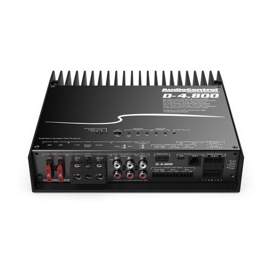
High Power Multi Channel Amplifier
with DSP Matrix Processor
Quick Start Guide
Advertisement
Table of Contents

Subscribe to Our Youtube Channel
Related Manuals for AudioControl D-4.800


Summary of Contents for AudioControl D-4.800
- Page 1 Features • 2/3/4 high power amplifier channels • 4x 125 W @ 4Ω, 4x 200 W @ 2Ω, 2x 400 W @ 4Ω Bridged • Smart User Interface software included • Input and Output RTA for precise and informed tuning •...
-
Page 2: Important Safety Instructions
Important Safety Instructions 14. This apparatus shall not be exposed to dripping or splashing, and no Read these instructions. object filled with liquids, shall be placed on the apparatus. Keep these instructions. 15. Fuses shall be replaced only with the correct type and fuse value, and Heed all warnings. - Page 3 12V remote trigger output of some head units. you follow the plus and minus polarity markings on the D-4.800 When the head unit is turned on, then the D-4.800 will turn on. and match it to the polarity of the speaker wiring. Speaker-level Alternatively, you can use the GTO™...
- Page 4 Repeated Short have detected a problem. See the table below. Under Voltage 10. Protection LED – The D-4.800 amplifier has built in diagnostic codes to tell you exactly what is going wrong should the amplifier Over Voltage detect a problem. Below is a list of diagnostic codes to help you...
- Page 5 Turn down the output levels if these LEDs are on a lot. 12. GTO™ Signal Sense – In the ON position, the D-4.800 amplifier 15. MILC Source Clip LED – The MILC™ (Maximum Input Level will turn on gracefully when it detects an incoming audio signal ™...
-
Page 6: Power Connections
Remote Alternatively, the GTO™ signal sense +12V Trigger feature can be used to gently turn on the D-4.800 when an audio input signal is detected at inputs 1-2. (Then the connection to the D-4.800’s remote input terminal is not required.) The +12V power wiring and Ground wir- ing should be between 8 and 3 AWG. - Page 7 System Examples continued System #1: Using speaker-level inputs ACR-3 (Optional) Factory Radio Speaker-level output Mids/Highs Front Full-Range Speaker-level output Subwoofer...
- Page 8 System Examples continued System #2: Using line-level inputs ACR-3 (Option) After-market Radio Speaker-level output Front Front Line-level output Speaker-level output Rear Rear Line-level output Subwoofer “The Epicenter” Subwoofer Amplifier Quick Start Guide...
- Page 9 System Examples continued System #3: Using an external subwoofer amplifier ACR-3 (Option) Factory Radio Speaker-level output Front Front Speaker-level output Speaker-level output Rear Rear Speaker-level output Subwoofer “The Epicenter” Subwoofer Amplifier...
-
Page 10: Installation
6. Use between 8 and 3 gauge insulated power cable to connect the +12V terminal of the D-4.800 to the positive terminal of the vehicle battery. Quick Start Guide... - Page 11 The top lid must be removed to gain access to the controls, and then control is a dual-function remote for your put back on again to protect the controls from dust bunnies. D-4.800. It may be mounted under the dash Removal Procedure using its own bracket, or through a custom 1.
-
Page 12: Quick Start
1. The following details give a brief overview of the steps required 11. When you are satisfied that all is looking good and correct, to install the D-4.800 in your system. The steps below are ex- reconnect the vehicle battery. Make sure that any external am- plained in more detail throughout the on-line manual. - Page 13 The goal of the Input View display is to get all of the signals arriving to the D-4.800 evenly balanced in level, and time-aligned so that they can be summed as desired later. The integrated Real Time Analyzer (RTA) is helpful in achieving this objective.
-
Page 14: Output View
EQ and AccuBASS® settings. The D-4.800 is exceptionally flexible, and can be configured to use any output in any band- width or source and match the needs of the installation. -
Page 15: Dashboard View
Software Application continued Dashboard View This display allows you to conveniently see the settings of any one input and any one output simultaneously. All of the controls work the same as the Input View and Out- put View. -
Page 16: Specifications
Specifications All specifications are measured at 14.4 VDC (standard automotive voltage). As technology advances, AudioControl reserves the right to continuously change our specifications, like our Pacific Northwest weather, although we are working on changing that as well. D-4.800 Digital input sample rate........32 - 96 kHz Power Output.
Need help?
Do you have a question about the D-4.800 and is the answer not in the manual?
Questions and answers