Klipsch RP-260F Service Manual
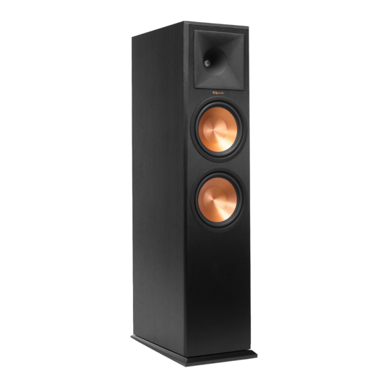
Floorstanding
speaker
Hide thumbs
Also See for RP-260F:
- User manual (49 pages) ,
- User manual (11 pages) ,
- User manual (12 pages)
Advertisement
KLIPSCH AUDIO TECHNOLOGIES
Reference Premiere RP-280F/RP-260F/RP-250F Floorstanding
Speaker Service Manual
Product Type: RP-280F/RP-260F/RP-250F
Manual Part #: 1061797
Model Line: Reference
Product Launch Year: 2015
The information contained in this document is solely intended for service and repair of Klipsch Group, Inc product;
use of this information to mimic or copy KGI designs is strictly prohibited and subject to prosecution.
T able of Contents
SPECIFICATIONS......................................................................................................................... 2
EXPLODED VIEW ........................................................................................................................ 5
WARRANTY PARTS LIST .......................................................................................................... 6
TROUBLESHOOTING GUIDELINES ....................................................................................... 7
RP-280F ..................................................................................................... 2
RP-260F ..................................................................................................... 2
RP-250F ..................................................................................................... 4
....................................................................................................................... 7
...................................................................................................................... 15
C
O
N
S
U
M
E
C
O
N
S
U
M
E
C
O
N
S
U
M
E
R
R
R
Advertisement
Table of Contents

Related Manuals for Klipsch RP-260F


Summary of Contents for Klipsch RP-260F
-
Page 1: Table Of Contents
Model Line: Reference Product Launch Year: 2015 The information contained in this document is solely intended for service and repair of Klipsch Group, Inc product; use of this information to mimic or copy KGI designs is strictly prohibited and subject to prosecution. -
Page 2: Specifications
Service Manual – Consumer Specifications Cut Sheet Data Model: RP-280F... - Page 3 Service Manual – Consumer Specifications Cut Sheet Data Model: RP-260F...
-
Page 4: Cut Sheet Data For Rp-250F
Service Manual – Consumer Specifications Cut Sheet Data Model: RP-250F... -
Page 5: Exploded View
Service Manual – Consumer Exploded View... -
Page 6: Warranty Parts List
1061147 RP-280F Woofer 1061107 RP-280F Grill 1061087 RP-280F Network Assy 1062493 Premiere Binding Post Shorting Straps (Pair) 1016198 Rubber Foot RP-260F Warranty Replacment Parts 1060814 Reference Premiere Tweeter 1061254 RP-260F Woofer 1061108 RP-260F Grill 1061086 RP-260F Network Assy 1062493 Premiere Binding Post Shorting Straps (Pair) -
Page 7: Troubleshooting Guidelines
Service Manual – Consumer Tweeter Removal for RP-280F, RP-260F, and RP-250F Tools needed: 3mm hex (Allen) key Small Flat Blade Screwdriver First, gently pry back the silicone tweeter horn lens with your finger-tips as illustrated below... - Page 8 Service Manual – Consumer...
- Page 9 Service Manual – Consumer Next, begin removing the screws from the perimeter of the tweeter, highlighted in below. There will be eight (8) total screws to remove, each using a 3mm hex key head.
- Page 10 Service Manual – Consumer...
- Page 11 Service Manual – Consumer Once all the screws have been removed, the tweeter and tweeter horn should come free as shown below. Once the tweeter is removed from the cabinet, slide back the silicone covers on the terminals, and use a small flat blade screw driver to release the wire clips holding to the positive and negative terminals of the tweeter.
- Page 12 Service Manual – Consumer After the tweeter is removed completely from the cabinet, turn the tweeter over with the magnet facing up. Next, begin removing the screws attaching the tweeter to the tweeter horn lens There will be four (4) screws total each using a #2 Philips head, highlighted in below...
- Page 13 Service Manual – Consumer...
- Page 14 Service Manual – Consumer Once the screws have been removed, the tweeter driver will come free as shown below. Next, place the new tweeter on the horn lens and replace the four (4) screws. Reattach the wire clips to the positive and negative terminals on the tweeter, and seat the tweeter back into position.
-
Page 15: Woofer Removal
Service Manual – Consumer Troubleshooting Guides Woofer Removal for RP-280F, RP-260F and RP-250F Tools needed: 3mm hex (Allen) key Small Flat Blade Screwdriver First, gently pry back the silicone trim ring with your finger-tips as illustrated on the next page... - Page 16 Service Manual – Consumer...
- Page 17 Service Manual – Consumer Once the trim ring is removed, begin removing the screws from the perimeter of the woofer. There are six (6) screws in total, each using a 3mm hex key head, highlighted in below.
- Page 18 Service Manual – Consumer...
- Page 19 Service Manual – Consumer Once the screws are removed, the woofer should come free as shown below.
- Page 20 Service Manual – Consumer Next, slide back the silicone covers on the terminals, and use a small flat blade screw driver to release the wire clips holding to the positive and negative terminals of the woofer...
- Page 21 Service Manual – Consumer Once the woofer is removed, the cabinet will look as shown below. Next, plug the wires on to the new woofer, and slide the silicone covers back over the terminals. Place the woofer back into position, and replace the screws. Replace the trim ring by setting into position and gently pressing the trim ring around the edge.
Need help?
Do you have a question about the RP-260F and is the answer not in the manual?
Questions and answers