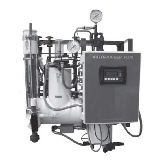
Hansen APP08 Operator Installation & Instruction Manual

Hansen APP08 Operator Installation & Instruction Manual

Auto-purger plus

Advertisement

AUTO-PURGER
The AUTO-PURGER Plus is a totally automatic, electronically-
controlled refrigerant noncondensible gas (air) and
water purger for reducing the energy costs of operating
an ammonia refrigeration system. All models are pre-
assembled, pre-wired, insulated, and include an automatic
Water Bubbler, a relief valve, and an isolation service valve
package. Installation requires piping the foul gas line, low-
pressure pumped-liquid line, low-pressure liquid return
line, suction line, water bubbler fill and drain lines, relief
valve vent line, water purge line to a customer supplied
container, and power connection, and wiring the remote
Purge Point Solenoid Valves. Purge point solenoid valves
must be purchased separately and must be a minimum
of ½" (13 mm) port size.
In addition, a computerized model—APPC—is available
where a separate plant computer or programmable logic
controller (PLC) is used to independently operate the
various remote purge point solenoid valves.
Water contamination in an industrial ammonia refrigeration
system can lower system efficiency, and increase the
electrical costs required to run the system's refrigeration
compressors. Ammonia refrigerant that is contaminated
with water requires a lower suction pressure to maintain
the same evaporator temperature than would pure
ammonia refrigerant.
lower suction pressure than would be necessary if the
water contamination were removed is a waste of electrical
energy. For water removal, the AUTO-PURGER Plus has
the following capacities:
5% system water concentration – 3 gallons of water
removed per day
10% system water concentration – 5 gallons of water
removed per day
20% or more system water concentration – 7 gallons of
water removed per day.
®
PLUS, APP
SECTION 1
The requirement to maintain a
Operator Installation
& Instruction Manual
AUTO-PURGER
Non-condensible Gas (Air) &
Water Purger for Ammonia
Operator Installation & Instruction
Manual for Models APP08, APP16,
APP24 and APPC

INTRODUCTION

The internal surface area and flooded evaporator efficiency
gives the AUTO-PURGER Plus two to three times the foul
gas condensing capacity of an Armstrong Purger and 10
times the capacity of purgers with small electric hermetic
compressors. In a system with normal noncondensible
loads, all models will handle a 750 ton (2600 kW) ammonia
plant at suction pressures below atmospheric pressure or
a 1500 ton (5300 kW) ammonia plant at positive suction
pressures. The amount of noncondensibles in the system
is based on many factors including age, maintenance
practices, and operating temperature.
The number of purgers required for a system depends on
the number of installed purge points. Twenty-four purge
points is the maximum practical number per purger. For
example, a system with 24 points set to purge for 10
minutes per point requires a 240 minute (4 hour) cycle.
Each purge point can be purged 6 times a day. This may, or
may not, be adequate. Therefore, a second purger should
be used and the purge points divided equally between
the two purgers.
The AUTO-PURGER Plus can operate over a wide range of
condensing pressures. This is important for refrigeration
systems that operate at low condensing pressures during
cold ambient conditions.
Bulletin APP-001b
APR 2007
®
PLUS, APP

Advertisement

Table of Contents
loading

Summary of Contents for Hansen APP08

  • Page 1 & Instruction Manual ® AUTO-PURGER PLUS, APP Non-condensible Gas (Air) & Water Purger for Ammonia Operator Installation & Instruction Manual for Models APP08, APP16, APP24 and APPC ® AUTO-PURGER PLUS, APP SECTION 1 INTRODUCTION The AUTO-PURGER Plus is a totally automatic, electronically-...
  • Page 2 SECTION 2 INSTALLATION MOUNTING INSTRUCTIONS FOUL GAS PIPING Mount the AUTO-PURGER Plus securely on a wall or It is nearly impossible to predict where noncondensible sturdy steel channels capable of supporting 450 lbs (205 gases (air) will accumulate. Therefore, purging at several Kg).
  • Page 3 The minimum line size for foul gas piping is ½” (13 mm). PURGE POINT LOCATIONS The line should be pitched down toward the purger to Condensers should be purged at points recommended by drain any refrigerant that may condense. the condenser manufacturer. This is typically at the top of each circuit’s outlet header.
  • Page 4 LOW-PRESSURE PUMPED-LIQUID LINE SUCTION LINE A ½” (13 mm) low-pressure pumped-liquid source is A ¾” (20 mm) suction line should be connected to a required for the AUTO-PURGER Plus. This connection suction accumulator. See Figure 3. The purger evaporator should be from the pump discharge of the lowest pressure shell temperature sensor is factory set at 40°F (4°C).
  • Page 5 PP_COM. WATER PURGE LINE Models APP08, APP16, and APP24 supply 115VAC to the purge points regardless of whether 115VAC or 220VAC is Water removed from the refrigeration system by the supplied to the control cabinet.
  • Page 6 SECTION 3 AUTO-PURGER PLUS OPERATION the liquid level gradually falls, causing the float ball to The AUTO-PURGER Plus is designed to automatically start- fall. This changes the SPDT switch position of the liquid up and operate without the assistance of plant personnel. level float switch and energizes the purge gas solenoid Beginning at start-up, the following is a description of valve (C) and the water bubbler fill line solenoid valve (D),...
  • Page 7 AUTO-PURGER PLUS APP FLOW DIAGRAM Figure 4 ½" FOUL ½" LOW-PRESSURE ½" LOW-PRESSURE ¾" SUCTION LINE GAS LINE PUMPED-LIQUID LINE LIQUID RETURN LINE STOP/CHECK VALVE GAUGE VALVE GAUGE VALVE STRAINER 300 PSI (20.7 BAR) RELIEF VALVE ½" WATER BUBBLER FILL LINE 225 PSID (15.5 BAR) RELIEF CHECK VALVE RELIEF VALVE 1 PSID (0.07 BAR) RELIEF CHECK VALVE...
  • Page 8 SECTION 4 CONTROL CONSOLE OPERATION CONTROL CONSOLE The four Control Pushbuttons allow navigation through the menu hierarchy. See Figure 5. The Control Console allows the operator to interface with the purger’s control software. Messages are displayed ESC – Switches between PLC messages and the Control in the Control Console Display Window.
  • Page 9 SYSTEM RESET – Resets the system to its pre-startup settings. Actions performed by pressing this key consist of clearing any error code(s), clearing air purge log minutes, clearing air purge log cycles, clearing water drain log minutes, clearing water drain cycles, stopping air and water purging processes if active.
  • Page 10 At system start-up, when a purger is initially installed in a system that has fewer purge points than are available on the purger (e.g., an APP08 used on system that has 5 purge points), the unused purge points must be set to 0.
  • Page 11 “Draining Water” will appear when removed water is MAINTENANCE ITEM, RTC BACKUP draining from the APP. BATTERY “Collecting Air/Water” will appear when the APP is operating Replacement Battery: normally. DURACELL DL2032 or RAYOVAC CR2032 “Startup Delay Mode” will appear for 10 minutes after the The coin cell battery, 3.0V Lithium, is used to provide APP evaporator shell cools to less than 40ºF (4ºC) and backup power to the real time clock.
  • Page 12 A 1 psid (.07 bar) relief check valve from the Models APP08, APP16, and APP24 supply 115VAC to the suction line to the float chamber. A 1 psid (.07 bar) check purge points regardless of whether 115VAC or 220VAC is valve in the water purge line to prevent reverse flow of supplied to the control cabinet.
  • Page 13 PURGE GAS SOLENOID VALVE Figure 7 1/4" PURGE GAS GAUGE VALVE WIDE OPEN DURING OPERATION CLOSED FOR SERVICING PURGER 1 PSID PURGE GAS (0.07 BAR) SOLENOID VALVE CHECK VALVE 1/32" (0.8 MM) DIA METERING ORIFICE DISC INSTALLED IN THE CHECK VALVE PURGE GAS TO WATER BUBBLER OR TO CUSTOMER SUPPLIED WATER BOTTLE APP-001b...
  • Page 14 SECTION 6 SERVICE, MAINTENANCE & PARTS PURGER PUMP OUT PROCEDURE, WITH AUTO-PURGER ON 1) Close the purge gas gauge valve to the water bubbler. 2) Close the low-pressure pumped-liquid line shut-off valve. 3) Close the foul gas line shut-off valve. 4) Close the water bubbler fill line valve.
  • Page 15 PARTS LIST MECHANICAL HLLSW Float Switch Assembly 20-1772 Water Bubbler Assembly, antisyphon (w/end connections) 20-1186 Metering Valve 20-1198 Metering Valve Seal Kit 20-1648 Metering Valve Strainer Screen Assembly Replacement Kit for above strainer, includes: 20-1737 20-1535 Screen Assembly 78-0016 Strainer Cap Gasket ST050 Water Purge Line Strainer Screen Assembly Replacement Kit for above strainer, includes:...
  • Page 16 SECTION 7 TROUBLESHOOTING CONTROL CONSOLE DISPLAYS 2222 CONTROL CONSOLE DISPLAYS 3333 LOSS OF “FOUL GAS” PRESSURE. This usually means P U R G E R T O O WA R M . If the pur g e r eva po r ato r the pressure in the air separator chamber is below 80 psig temperature is 40°F (4.4°C) or warmer, the purger will (5.5 barg).
  • Page 17 CONTROL CONSOLE DISPLAYS 4444 NONCONDENSIBLES ARE NOT BEING RELEASED. PURGED OVER 60 MINUTE TIME LIMIT. If noncondensibles are released from the purger for 60 minutes continuously, a (See also page 16; Control Console displays 3333) time delay will close the purge gas solenoid valve (C). This REASON 1: Noncondensibles not present in system.
  • Page 18 THIS PAGE INTENTIONALLY BLANK APP-001b APR 2007...
  • Page 19 ORDERING INFORMATION CAUTION Hansen purgers are for refrigeration systems only. These Cat. No. Description instructions and related safety precautions must be read APP08 AUTO-PURGER Plus, 8 points completely and understood before selecting, using, or servicing these purgers. Only knowledgeable, trained...
  • Page 20 6827 High Grove Boulevard Burr Ridge, Illinois 60527 USA Tel: 630.325.1565 Fax: 630.325.1572 Toll: 800.426.7368 Email: info@hantech.com Web: www.hantech.com USA ∙ Asia ∙ Europe ∙ India ∙ Latin America ∙ Middle East © 2007 Hansen Technologies Corporation APP-001b APR 2007...

This manual is also suitable for:

AppcApp16App24

Table of Contents