Table of Contents
Advertisement
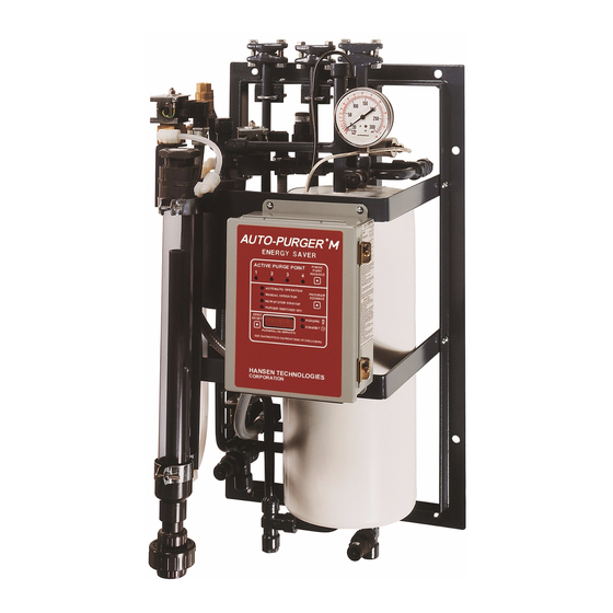
Model APM
INTRODUCTION
The AUTO-PURGER® M is a compact and totally automatic,
electronically-controlled, noncondensible gas refrigerant
purger for reducing condensing pressure, and thereby
saving electrical energy used by the refrigeration system.
This deluxe purger is preassembled, prewired, tested,
insulated, and includes an automatic water bubbler.
Installation requires piping the foul gas line, liquid line,
Suction Line, water line, drain line, and wiring the power
connection and the remote ½" (13 mm) port purge point
Solenoid Valves, which must be purchased separately. Up
to four (4) purge points can be controlled by this purger.
The AUTO-PURGER® M (APM) features welded piping
and watertight electrical construction. The APM meets
the requirements of the Canadian Standards Association
(CSA certified).
A typical APM installed in a plant with normal-entering
noncondensible loads will handle up to a 200 ton (700 kW)
system. Each purge point will be active between 10 and 30
minutes, depending on the noncondensible gas presence
(mostly air) and the purger mode of operation.
Model APMF AUTO-PURGERS are for use in halocarbon
refrigeration systems. The installation and operation of
these AUTO-PURGERS are similar to that of an ammonia
AUTO-PURGER M. See page 13 for additional details.
MOUNTING INSTRUCTIONS
Mount the APM straight and securely on a wall or sturdy
steel channels capable of supporting 350 lbs (160 Kg). Eight
mounting holes in the frame are provided to support the
purger (See Figure 1). The APM should be located in an
accessible area, but away from the movement of equipment
that could accidentally damage the purger. Elevation with
respect to condensers or high-pressure receivers is not
critical, however, purge point solenoid valves must be
above the purger.
SECTION 1 MOUNTING & PIPING INSTALLATION
Specifications, Applications,
Service Instructions & Parts
AUTO-PURGER
"Energy Saver"
Compact, Non-condensible
Gas (Air) Purger
For Models APM & APMF
An APM is usually installed in the compressor room where
it can be monitored, but also may be installed outdoors
where temperatures below freezing are not anticipated.
The APM comes standard with a watertight NEMA 13 (IP65,
Category 2) control cabinet enclosure with sealed conduit
wiring. Any unused electrical entrances to the enclosure
must be sealed to protect electronics from moisture. A
NEMA 4 cabinet enclosure is available.
An optional valve package (VPM) for purger isolation is
available from Hansen. This consists of three welded
assemblies which include shut-off valves, gauge valves,
and mating flanges. An illustration detailing this optional
valve package is on page 12 (Figure 13).
FOUL GAS PIPING
Purging at several points, up to four with the APM, on the
high-pressure side of the system is the best method for
removing foul gas. Foul gas is refrigerant gas containing
some air or other noncondensibles. Several points should
be used because it is nearly impossible to predict where
noncondensible gas will accumulate in a system.
Even for multipoint purging, only one purge point should be
purged at a time. Connecting two purge points from two
condensers or receivers may result in gas flowing from one
condenser to another. This is due to an unequal pressure
drop, even though the differences in pressure drop are
very small, for example ¼ psig (0.02 bar). The result would
be that, even in the best of circumstances, only one point
is effectively purged. The best practice is to purge each
condenser and receiver circuit separately.
When utilizing multipoint purging, the purge point solenoid
valves can be manifolded into one foul gas line to the
purger. A ½" (13 mm) size line is the minimum and should
be pitched toward the purger to drain any condensed
liquid. Also, no liquid traps are allowed either before or
after the purge point solenoid valves (See Figure 2). The
foul gas line should not pass through cold areas where
Bulletin APM-001e
AUG 2015
M
®
Advertisement
Table of Contents

Subscribe to Our Youtube Channel
Related Manuals for Hansen AUTO-PURGER M

Summary of Contents for Hansen AUTO-PURGER M
- Page 1 AUTO-PURGERS are similar to that of an ammonia condenser to another. This is due to an unequal pressure AUTO-PURGER M. See page 13 for additional details. drop, even though the differences in pressure drop are MOUNTING INSTRUCTIONS very small, for example ¼...
- Page 2 Refer to ASHRAE GUIDELINES or IIAR It is important that all purge points be located above any Papers on condenser piping design. Hansen Technologies liquid surfaces to avoid drawing liquid refrigerant, rather can provide copies of these articles. Also, consult the than vapor, into the APM.
- Page 3 SECTION 1 MOUNTING & PIPING INSTALLATION TYPICAL APPLICATION Figure 2 PURGE POINT VALVE (TYPICAL) Figure 3 1/2" (13 MM) PORT REMOTE PURGE POINT ISOLATION SOLENOID VALVE SHUT-OFF VALVE LEVEL OR PITCH DOWN TO PURGER CLOSE-COUPLED STRAINER ISOLATION SHUT-OFF VALVE (GLOBE VALVE STEM HORIZONTAL FROM FOUL GAS SOURCE IS PREFERRED) APM-001e...
- Page 4 SECTION 1 MOUNTING & PIPING INSTALLATION PURGE POINT CONNECTIONS WATER LINE Foul gas lines from condensers should be purged at points The APM has an automatic water bubbler to eliminate any recommended by the condenser manufacturer. Usually, this water bottle attention. Connect the water supply to the is at the top of each circuit’s outlet header which drains purger water shut-off valve (See Figure 1).
- Page 5 SECTION 2 ELECTRICAL INSTALLATION & OPERATION ELECTRICAL CONNECTIONS wire purge point solenoid coils. Carefully study the wiring The standard electrical requirement for the APM is 115V diagram below (Figure 5) to avoid electrical short circuits. 50/60 Hz. Also available is 230V 50/60 Hz. Main supply Connect electrical wiring from each purge point solenoid to voltage fluctuations should not to exceed ±...
- Page 6 NEW SYSTEM STARTUP PURGER SWITCHED OFF ZERO PURGING RESET STANDBY PURGING LOG PURGING LOG (MINUTES) (DIAGNOSTIC CODE WHEN FLASHING) RESET BUTTON SEE DIAGNOSTICS ON RIGHT SIDE OF ENCLOSURE CONTROL CABINET ENCLOSURE DIGITAL READOUT HANSEN TECHNOLOGIES CORPORATION PURGER STATUS LIGHTS APM-001e AUG 2015...
- Page 7 SECTION 2 ELECTRICAL INSTALLATION & OPERATION ACTIVE PURGE POINT PURGE POINT ENABLE SWITCHES The front of the control cabinet has lights which indicate These switches are located on the control board and are the active purge point. The active purge point can be all factory-set to the ON position.
- Page 8 In addition, separate remote point solenoid valves are required, one for each enabled purge point. These are not included with the APM. The Hansen type HS8 solenoid valve having a ½” (13mm) port and a stainless steel piston is recommended. Below is a typical purge point solenoid valve with close-coupled strainer (Figure 9).
- Page 9 SECTION 3 APM OPERATION OPERATION The APM is designed to automatically start-up and operate without the assistance of plant personnel. Beginning at The foul gas may carry a certain amount of condensed start-up, the following is a description of the refrigerant refrigerant which is captured by the liquid drainer before flow through a purger.
- Page 10 SECTION 4 TROUBLE SHOOTING PURGER OPERATION DIGITAL READOUT FLASHING 2222 Check: Inspect the suction line and shut-off valves. These should be a minimum size of ¾”. On new installations, LOSS OF FOUL GAS PRESSURE. This usually means also make sure the plastic shipping cap in suction line the pressure in the air separator chamber is below 80 psig flange is removed.
- Page 11 SECTION 4 TROUBLE SHOOTING PURGER OPERATION DIGITAL READOUT FLASHING 7777 DIGITAL READOUT FLASHING 5555 LOSS OF HIGH PRESSURE LIQUID. If the liquid line PURGER SHUT-OFF REMOTELY. This code indicates solenoid valve remains energized for more than 30 minutes, it that the optional interlock remote relay contacts are open. indicates there is insufficient high-pressure liquid available These contacts are connected to the purger via the power/ to maintain an adequate level in the flooded evaporator...
- Page 12 SECTION 4 TROUBLE SHOOTING PURGER OPERATION NONCONDENSIBLES ARE NOT BEING AMMONIA INSTEAD OF NONCONDENSIBLES RELEASED FROM PURGER. RELEASED. (See also page 10; Digital Readout Flashing 3333) (See also page 10; Digital Readout Flashing 3333) REASON 1: Noncondensibles not present in system. REASON 1: Purge gas solenoid valve (C) leaking at seat.
- Page 13 OPTIONAL VALVE PACKAGE FOR AMMONIA SYSTEMS (VPM) Figure 13 FOUL GAS LINE LIQUID LINE SUCTION LINE SHUT-OFF VALVE ½" SOCKET WELD ½" SOCKET WELD ¾" SOCKET WELD (VIEW ROTATED FOR CLARITY) GAUGE VALVE 1/4" NPT PIPE THREAD GAUGE VALVE 1/4" NPT PIPE THREAD PURGER FRAME APM-001e...
- Page 14 SECTION 5 APMF AUTO-PURGER M FOR HALOCARBON SYSTEMS INTRODUCTION OPTIONAL VALVE PACKAGE, VPMF Model APMF AUTO-PURGERs are for use in halocarbon The special construction for APMF AUTO-PURGERs includes refrigeration systems. The installation and operation of a filter-dryer conditioning system for the foul gas and liquid these AUTO-PURGERs are similar to that of an ammonia line.
- Page 15 Foul Gas/Liquid Line Strainer Kits 78-1010 include Strainer Basket and O-Ring ORDERING INFORMATION, OPTIONAL VALVE ORDERING INFORMATION, PURGER PACKAGE Cat. No. Description Auto-Purger M, 4 points, Cat. No. Description for ammonia systems Valve Package for ammonia systems Auto-Purger M, 4 points, APMF VPMF...
- Page 16 CAUTION a u t o m a t i c s t a r t- u p w i t h Hansen purgers are for refrigeration systems only. These electronic control. Designed instructions and related safety precautions must be read...
Need help?
Do you have a question about the AUTO-PURGER M and is the answer not in the manual?
Questions and answers