Table of Contents
Advertisement
Quick Links
Advertisement
Table of Contents

Related Manuals for Dahua ESS2016X


Summary of Contents for Dahua ESS2016X
- Page 1 ESS Series Internet Intelligent Storage User’s Manual V 2.1.0...
-
Page 2: Table Of Contents
OVERVIEW ......................1 Model List ............................1 1.1.1 Host Model ........................... 1 1.1.2 Disk Array Enclosure Model ....................... 1 Connection Sample.......................... 1 ESS2016X ............................2 1.3.1 Front Panel........................... 2 1.3.2 Rear Panel ........................... 2 ESS3116X ............................3 1.4.1 Front Panel........................... 3 1.4.2... - Page 3 ESS5016D-R ..........................18 1.9.5 ESS5024S/ ESS5024S-R ......................19 1.9.6 ESS5024D-R ..........................20 1.10 Disk Array Enclosure Specifications ..................... 21 1.10.1 ESS2016X-J .......................... 21 1.10.2 ESS3116S-J/ ESS3116S-JR/ESS3116D-JR ..............22 1.10.3 ESS3124S-J/ ESS3124S-JR/ESS3124D-JR ..............23 1.10.4 ESS3148S-J/ ESS3148S-JR ....................24 INSTALLATION....................26 HDD Installation ..........................
- Page 4 ESS Series User’s Manual 3.2.3 Account ............................34 3.2.4 Guide ............................36 3.2.5 Enclosure ........................... 36 3.2.6 Performance ..........................37 3.2.7 Upgrade............................38 3.2.8 Shut down System........................39 3.2.9 Version ............................40 Network Management........................40 3.3.1 Network Configuration ....................... 40 3.3.2 Virtual Network (For dual-controller series product only) ............
- Page 5 4.3.3 Access FTP Share Directory ....................80 4.3.4 Access iSCSI Share Directory ....................80 DISK ARRAY ENCLOSURE ................81 HDD Installation ..........................81 ESS2016X-J ........................... 81 5.2.1 Front Panel..........................81 5.2.2 Rear Panel ..........................81 5.2.3 Disk Array Enclosure Cascade Connection................82 ESS3116S-J/ESS3116S-JR ......................
- Page 6 ESS Series User’s Manual 5.5.1 Front Panel..........................86 5.5.2 Rear Panel ..........................86 ESS3124D-JR ..........................88 5.6.1 Front Panel..........................88 5.6.2 Rear Panel ..........................88 ESS3148S-J/ ESS3148S-JR ......................89 5.7.1 Front Panel..........................90 5.7.2 Rear Panel ..........................90 Disk Array Enclosure Cascade Connection ................. 93 5.8.1 Cascade Connection Sheet ......................
- Page 7 ESS Series User’s Manual APPENDIX C---ISCSI APPLICATION IN MS WINDOWS ....... 104 APPENDIX D—PUTTY TERMINAL ..............111 Login ............................. 111 Configuration Menu........................113 9.2.1 View System Info ........................113 9.2.2 Reset Password........................113 9.2.3 Network Settings ........................113 9.2.4 Super User ..........................113 10 APPENDIX E ---GLOSSARY ................
- Page 8 ESS Series User’s Manual Welcome Thank you for using our internet intelligent storage system! This user’s manual is designed to be a reference tool for the installation and operation of your system. Before installation and operation please read the following safeguards and warnings carefully!
- Page 9 ESS Series User’s Manual Important Safeguard and Warnings 1.Electrical Safety All installation and operation should conform to your local electrical safety codes. The product must be grounded to reduce the risk of electric shock. We assume no liability or responsibility for all the fires or electric shock caused by improper handling or installation.
-
Page 10: Overview
This user’s manual is to introduce the following products. Please refer to the following sheet for detailed information. 1.1.1 Host Model Model Case HDD No. Power Mode Network Setup Controller Height ESS2016X Single-power LAN1/LAN2/WEB supplying ESS3116X Single-power LAN1/LAN2/LAN3/LAN4 supplying ESS5016S/ Single-power... -
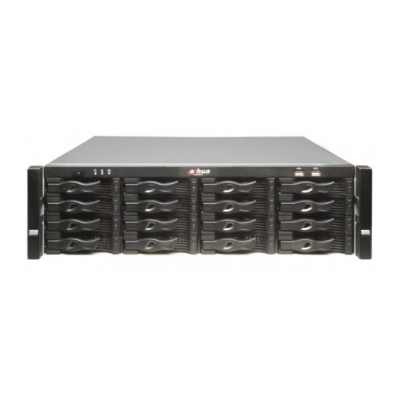
Page 11: Ess2016X
ESS Series User’s Manual Figure 1-1 1.3 ESS2016X 1.3.1 Front Panel The front panel is shown as below. See Figure 1-2. The HDD slot number ranges from left to right, from top to the bottom. Figure 1-2 Name Function Power on-off button Press it to boot up the device. -
Page 12: Ess3116X
ESS Series User’s Manual Figure 1-3 Port Function Power on-off button Connect or cut off the device power. Power Port Connect to AC power supplying. Case fan It is for case ventilation. Power fan It is for power ventilation SAS port Connect to IN port of the disk array enclosure. -
Page 13: Rear Panel
ESS Series User’s Manual Figure 1-4 Name Function Power on-off button Press it to boot up the device. Press it for a long time to reboot the device. System When system HDD is reading or writing, the blue light becomes flash. Indicator Light The system HDD storage the important configuration files of the device, factory default configuration files and device initial boot up data. -
Page 14: Ess5016S/ Ess5016S-R
ESS Series User’s Manual Figure 1-6 You can refer to the following sheet for detailed information. Port Function Power Port Connect to 220V AC. Blowing machine It is for ventilation. It is for ventilation. Ethernet port It is used to transmit data. 1000M Ethernet port. VGA port Connect to monitor. -
Page 15: Rear Panel
ESS Series User’s Manual Figure 1-8 Please refer to the following sheet for detailed information. Name Function Power on-off button Press it to boot up the device. Press it for 5 seconds to shut down the device. HDD Indicator Light When system HDD is reading or writing, the blue light becomes flash. -
Page 16: Ess5016D-R
ESS Series User’s Manual Figure 1-10 You can refer to the following sheet for detailed information. Port Function Power Port Connect to AC power supplying. Case fan It is for case ventilation. Power fan It is for power ventilation Main control module It is about all kinds of ports and indictor light introduction. -
Page 17: Rear Panel
ESS Series User’s Manual The HDD slot number ranges from left to right, from top to the bottom. Figure 1-11 Figure 1-12 One kind of the front panel is shown as below. See Figure 1-12 Please refer to the following sheet for detailed information. Name Function Power on-off button... -
Page 18: Ess5024S/ Ess5024S-R
ESS Series User’s Manual Figure 1-13 You can refer to the following sheet for detailed information of the rear panel. Port Function Power port Connect to AC power supplying source. Battery box It is to install the battery box. It is for case ventilation. Main control module It is about all kinds of ports and indictor light introduction. -
Page 19: Rear Panel
ESS Series User’s Manual The front panel is shown as below. See Figure 1-14. The HDD slot number ranges from left to right, from top to the bottom. Figure 1-14 Figure 1-15 One kind of the front panel is shown as below. See Figure 1-15 You can refer to the following sheet for detailed information. - Page 20 ESS Series User’s Manual Figure 1-16 The redundancy-power supplying rear panel is shown as below. See Figure 1-17. Figure 1-17 You can refer to the following sheet for detailed information of the rear panel. Port Function It is for case ventilation. Power port Connect to AC power supplying source.
-
Page 21: Ess5024D-R
ESS Series User’s Manual 1000Mbps data Ethernet port. It is to transmit data. LAN1~LAN4 10000Mbps data Ethernet port. It is to transmit data. (Optional) 10G_1, 10G_2 WEB port Ethernet Management port. Login Web via this port. USB port USB port PORT1/PORT2 Connect to the IN port of the disk array enclosure. -
Page 22: Rear Panel
ESS Series User’s Manual Figure 1-19 You can refer to the following sheet for detailed information. Name Function ① Power on-off button Press it to boot up the device. Press it for 5 seconds to shut down the device. ② HDD Indicator Light When system HDD is reading or writing, the blue light becomes flash. -
Page 23: Host Specifications
The error light is off when system is running properly. CACHE It is reserved for future use. Press it for 5 seconds to restore default setup (network setup, user password, time sync, email alarm and etc.). 1.9 Host Specifications 1.9.1 ESS2016X Model ESS2016X System Main Multiple-core special storage CPU... -
Page 24: Ess3116X
ESS Series User’s Manual Model ESS2016X Each HDD max supports 4T. RAID Mode RAID0/RAID1/RAID3/RAID5/RAID6/RAID10/RAID50/RAID60/JBOD/ one HDD/hotspare HDD. Independent HDD bracket. Support HDD hot swap. Installation Support global/private hotspare HDD Hotspare Disk Array Max 2-level cascade connection. Enclosure Network Port Management... -
Page 25: Ess5016S/ Ess5016S-R
ESS Series User’s Manual Model ESS3116X-NS ESS3116X-ES ESS3116X-NR ESS3116X-ER Setup Interface WEB GUI Storage Storage SAMBA/NFS/iSCSI/CIFS/FTP/HTTP/AFP Protocol Protocol Video Input Video 192-channel D1: 2Mbps Capacity 96-channel 720P: 4Mbps 48-channel 1080P: 8Mbps Data HDD No. 16 SATAⅡHDDs. Management Each HDD max supports 4T. RAID Mode RAID0/RAID1/RAID3/RAID5/RAID6/RAID10/RAID50/RAID60/SRAID /JBOD/ one HDD/hotspare HDD. - Page 26 ESS Series User’s Manual Model ESS5016S ESS5016S-R Redundant dual ball bearing fan MTBF>100 thousand hours Motherboard Server(Support 7x24H work) Storage Default 4G. With ECC verification. Max 8G Case Self-developed case, 1.2mm extra-thickness hot-dip galvanized steel. Self-developed patent removable HDD bracket. SBB2.0 specifications compliance.
-
Page 27: Ess5016D-R
ESS Series User’s Manual Model ESS5016S ESS5016S-R Storage 5%~90% (Non condensation) Environment Humidity Working -60m~5000m Altitude 1.9.4 ESS5016D-R Model ESS5016D-R System Controller Dual-controller Main Two Intel multiple-core processors processer Embedded LINUX OS Power Mode 500W. Redundancy 1+1power supplying mode. Support online update. Redundant dual ball bearing fan MTBF>100 thousand hours Motherboard... -
Page 28: Ess5024S/ Ess5024S-R
ESS Series User’s Manual Model ESS5016D-R Dimensions 448mm×133mm ×472mm (No front panel) (W×H×D) Installation Standard 19-inch rack installation Mode Net Weight 30kg (No HDD) Environments Working 0℃~40℃ Requirements Environment Temperature Working 10%~80% (Non condensation) Environment Humidity Storage -20℃~70℃ Environment Temperature Storage 5%~90% (Non condensation) Environment... -
Page 29: Ess5024D-R
ESS Series User’s Manual Model ESS5024S ESS5024S-R Support global hotspare HDD and special hotspare HDD. Hotspare Disk Array Max 4-level cascade connection. Enclosure Network Port Management One 10/100/1000Mbps Ethernet port Network Port Data Network Four 10/100/1000Mbps Ethernet ports. port Support load balance and network adapter binding. Extend to four 1000Mbps data port or two 10000Mbps data port. -
Page 30: Disk Array Enclosure Specifications
Mode Net Weight 34kg (No HDD) Environments Working 0℃~40℃ Requirements Environment Temperature Working 10%~80% (Non condensation) Environment Humidity Storage -20℃~70℃ Environment Temperature Storage 5%~90% (Non condensation) Environment Humidity Working -60m~5000m Altitude 1.10 Disk Array Enclosure Specifications 1.10.1 ESS2016X-J Model ESS2016X-J... -
Page 31: Ess3116S-J/ Ess3116S-Jr/Ess3116D-Jr
ESS Series User’s Manual Model ESS2016X-J System Main processer Special storage CPU Embedded LINUX OS Power Mode Single power supplying mode Redundant dual ball bearing fan MTBF>100 thousand hours Motherboard Server(Support 7x24H work) Case Self-developed case, 1.2mm extra-thickness hot-dip galvanized steel. -
Page 32: Ess3124S-J/ Ess3124S-Jr/Ess3124D-Jr
ESS Series User’s Manual Model ESS3116S-J ESS3116S-JR ESS3116D-JR SBB2.0 specifications compliance. Setup and system upgrade via the WEB GUI of the host. Data HDD Amount 16 HDDs. 16 HDDs. Management Support SAS/SATA HDD. Support SAS Each HDD max supports 6T. /SATA (need an adapter. -
Page 33: Ess3148S-J/ Ess3148S-Jr
ESS Series User’s Manual Model ESS3124S-J ESS3124S-JR ESS3124D-JR Data HDD Amount 24 HDDs. 24 HDDs. Management Support SAS/SATA HDD. Support SAS Each HDD max supports 6T. /SATA (need Support 2.5-inch HDD. adapter. NOT PROVIDED ) HDD. Each HDD max supports 6T. Support 2.5-inch HDD. - Page 34 ESS Series User’s Manual Model ESS3148S-J ESS3148S-JR Dimensions(W×H×D) 445mm×353mm×495mm Installation Mode Standard 19-inch rack installation Net Weight 48.32kg (No HDD) 49.92kg (No HDD) Environments Working Temperature 0℃~40℃ Working Humidity 10%~80%(Non condensation) Storage Temperature -20℃~70℃ Storage Humidity 5%~90%(Non condensation) Working Altitude -60m~5000m...
-
Page 35: Installation
ESS Series User’s Manual 2 Installation 2.1 HDD Installation Important We STRONGLY recommend the enterprise class disk. We are not liable for any problem (such as data loss) resulting from the HDD instability. For one device, please use the HDDs of the same brand and of the same space. ... -
Page 36: Battery Installation
ESS Series User’s Manual After you install the HDD, you need to install the front panel on the device. It is to reduce the risk of HDD stealing or mistakenly remove operation. Put the front panel to face you and make sure all lock holes are matching. Slowly push the front panel to the device. -
Page 37: Boot Up
ESS Series User’s Manual Figure 2-3 2.5 Boot up Please boot up he disk array enclosure first if the host is connected to the disk array enclosure. Connect the power cable to the system. Press the device power on-off button at the rear panel to ON to boot up the system (Please skip this step if there is no on-off button at the rear panel). -
Page 38: Network Setup
ESS Series User’s Manual Figure 2-4 Tips In each interface, click the shut down button at the top right corner to shut down the device. See Figure 2-4. 2.7 Network Setup Internet intelligent storage product default network setup is 192.168.0.111. It may be different from you current network IP section. - Page 39 ESS Series User’s Manual Figure 2-5 c) Open IE browser, input http://192.168.0.111(default IP address) you can see the login interface. System user name is admin and password is 888888888888(16-digit). d) In the main interface, from network to network and then click edit button .
- Page 40 ESS Series User’s Manual environment, input the command: ping 192.168.0.111 to test network connection is right or not.
-
Page 41: Host Configuration
ESS Series User’s Manual 3 Host Configuration All the figures listed are based on the ESS5016S series product. Slight difference may be found in the user interface if you are using other series products. 3.1 Login Please refer to chapter 2.7 to connect host to the network and then follow the steps listed below to login the WEB. -
Page 42: System
ESS Series User’s Manual 3.2.1 System After you logged in, you can see system information interface. Or you can click system and then select system information item to go to current interface. For dual control series product, you can see the statuses of dual controllers. Here you can see the following information: ... -
Page 43: Account
ESS Series User’s Manual Figure 3-2 3.2.3 Account Click Account button, you can see the following interface. See Figure 3-3. Here you can view system user information. You can add/edit/delete user. Please refer to the following sheet for detailed information. Type User Default... - Page 44 ESS Series User’s Manual Click here to logout current user and switch account to login again. Figure 3-3 3.2.3.1 Edit User Click edit button of corresponding user, you can see the following interface. See Figure 3-4. For the administrator, you do not need to input old password. You just input new password and confirm, you can modify a user’s password.
-
Page 45: Guide
ESS Series User’s Manual 3.2.3.2 Add User Note System can only add ordinary user such as user01. It has the same rights as the guest. In Figure 3-3, click add button, you can see the following interface. See Figure 3-5. After input new user information such as user name, user type, user type, please click save button. -
Page 46: Performance
ESS Series User’s Manual After you logged in as the system administrator, in Enclosure interface, you can view main host and disk array enclosure information, temperature, power voltage status, fan status. Here you can view disk array enclosure version if you want to update its software. You can also go to this interface to check the update operation is successful or not. -
Page 47: Upgrade
ESS Series User’s Manual Figure 3-7 3.2.7 Upgrade Important Before you upgrade the system, please go to our official website to download the latest version. Before you upgrade, please stop iSCSI service and RAID synchronization. The upgrade process may take a few minutes, please wait patiently. DO NOT TURN OFF THE DEVICE OR UNPLUG THE POWER WIRE. -
Page 48: Shut Down System
ESS Series User’s Manual Figure 3-8 3.2.7.2 Upgrade disk array enclosure Administrator can select disk array enclosure from the dropdown list and upgrade the disk array enclosure. See Figure 3-8. 3.2.8 Shut down System Click shut down system button; you can see the following interface. See Figure 3-9. Please note the following interface is based on the dual-controller series product. -
Page 49: Version
ESS Series User’s Manual 3.2.9 Version In this interface, you can check the version information of each module. 3.3 Network Management 3.3.1 Network Configuration Important We STRONGLY recommend you set the management network port and data network port to different network environments. ... - Page 50 ESS Series User’s Manual ESS2016X ESS2016X network port is shown as in Figure 3-11. Figure 3-11 Ethernet Port Main Function Management Port eth0 Use this port to login to the WEB interface. Data Port eth1/eth2 Use this port to read/write data.
- Page 51 ESS Series User’s Manual The following figure for reference only. Figure 3-13 3.3.1.2 Edit network card In Figure 3-10 click edit button , you can see the following interface. After your modification (such as IP address, subnet mask, default gateway and etc), please click save button to exit. See Figure 3-14.
-
Page 52: Virtual Network (For Dual-Controller Series Product Only)
ESS Series User’s Manual This function allows you to binding two physical network adapters to one virtual adapter to provide load balance or redundancy function to enhance bandwidth. In this mode, when one adapter is malfunction, the other one can still work and has no effect on the system operation. Please select two network adapters first and then input IP address, subnet mask and default gateway. -
Page 53: Disk Management
ESS Series User’s Manual Figure 3-16 3.4 Disk Management Disk management is to display HDD physical information in the system. It includes: channel number, disk space, disk status, RAID group name, usage status, disk No. 3.4.1 Disk Information Click disk button, you can see the following interface. See Figure 3-17. The disk amount displayed here for reference only. - Page 54 ESS Series User’s Manual Figure 3-17 3.4.1.1.1 Enable/disable disk indicator light In Figure 3-17, click enable HDD indicator light, you can turn on the corresponding HDD indicator light. . 3.4.1.1.2 Initialization Click and then select disk initialization, you can format the idle disk. Disk initialization has great effect on the data security.
- Page 55 ESS Series User’s Manual Figure 3-18 Important Please disable MAID function if the disk read-write operation is frequent. Otherwise, the frequent boot up and stop operation is going to reduce disk life span. 3.4.1.1.4 Add hotspare disk This series product support global hotspare disk. That is to say, the whole RAID groups share hotspare disk.
- Page 56 ESS Series User’s Manual Figure 3-19 3.4.1.1.5 Remove hotspare disk In Figure 3-17, select a disk and then click remove hotspare disk button. Click save button to delete it from the hotspare disk list and its status becomes idle. 3.4.1.1.6 Check and repair Select disk(s) you want to detect from the idle disks list and then click Check button you can see the following interface.
- Page 57 ESS Series User’s Manual 3.4.1.2 Additional Info In Figure 3-17, click Additional Info button, you can see the following interface. See Figure 3-21. Here you can view disk model, link speed, SN, firmware and manufacturer and etc. Figure 3-21 3.4.1.3 S.M.A.R.T In Figure 3-17, click S.M.A.R.T button, you can see the following interface.
-
Page 58: Raid Configuration
ESS Series User’s Manual Figure 3-22 3.4.2 RAID Configuration Click RAID button, you can see an interface is shown as in Figure 3-23. If the logged in account is ordinary user, you can only view the RAID information. If the logged in account is administrator, you can view/edit/delete/add RAID group. Status Note clean... - Page 59 ESS Series User’s Manual Figure 3-23 3.4.2.1 Add RAID configuration Click add button, you can see the following interface. In Figure 3-24, administrator can select RAID type (RAID0, RAID1, RAID5, RAID6, and JBOD) and then select the member disk. The damaged or used disks will not be listed in current interface.
- Page 60 ESS Series User’s Manual Figure 3-24 3.4.2.2 Remove RAID configuration Select OP and then select Remove, you can remove the RAID. The remove operation consists of the following three situations. You can refer to Figure 3-23. If current RAID is free (there is no storage pool, you can just click remove button to remove it directly.
-
Page 61: Pool Configuration
ESS Series User’s Manual Figure 3-25 3.4.2.4 Forced Assembly When the device boots up, there is no RAID. You can see “Inactive” status on the Web. You can click the Forced Assembly button to form a group. 3.4.2.5 Enable/Disable Positioning Light Click , select Enable/Disable Positioning Light, you can turn on or turn off the indicator light of corresponding disk(s) of the RAID group. - Page 62 ESS Series User’s Manual Figure 3-26 3.4.3.1 Add Pool In Figure 3-26, click add button, you can see the following interface. See Figure 3-27. Here you can select RAID device (RAID0, RAID1, RAID5, RAID6, JBOD and etc), single disk (such as disk1) to create a storage pool. Click save button after creating storage pool device. You can see the disk array enclosure from the location dropdown list if you have connected to the disk array enclosure.
-
Page 63: Logic Volume
ESS Series User’s Manual Click remove button if there is no logic volume in the storage pool. You can see a dialogue box pops up if there is a logic volume. You need to delete logic volume first and then remove the storage pool. 3.4.4 Logic Volume After you login the WEB as the administrator, you can add/delete logic volume or add space. - Page 64 ESS Series User’s Manual Figure 3-29 3.4.4.2 Remove logic volume You can remove the logic volume if it is not in use. 3.4.4.3 Extend logic volume Click and then select extend logic volume; you can add its space. See Figure 3-30. Please note this function is only valid when the logic volume is not in use.
- Page 65 ESS Series User’s Manual Please note this function is only valid when it is not in use. Figure 3-31 3.4.4.5 Clone Note The dual-controller host does not support this function. The clone function can provide the total data of the original status at the specified time. After the clone operation, even all original data is damaged, you can use clone logic volume to restore the data.
- Page 66 ESS Series User’s Manual Figure 3-32 Check the clone logic volume (clone LV) and then click Save button. Click and then select Start clone, system begins cloning logic volume. You can termiane the clone operation if it is in process. Or you can delete it after the clone operation.
-
Page 67: Senior
ESS Series User’s Manual Figure 3-33 Input remote backup address and then click Next button. Select the backup object and then click Next button. Select the backup LV and then click the Finish button. Click , select begin remote backup button, system begins backup logic volume remotely. You can termiane the remote backup operation if it is in process. - Page 68 ESS Series User’s Manual Figure 3-34 3.5.1.1 Add thin pool Figure 3-35. Click Add button, system goes to the following interface. See Figure 3-35 3.5.1.2 Delete thin pool There are two situations: If there is no thin LV on the thin pool, you can just click remove button to delete. ...
-
Page 69: Thin Lv Setup
ESS Series User’s Manual Figure 3-36 3.5.2 Thin LV Setup Login as the admin and then go to the Thin LV interface. You can add/remove thin LV. See Figure 3-37. Figure 3-37 3.5.2.1 Add thin LV Click Add button, you can go to the Add thin LV interface. See Figure 3-38. -
Page 70: Snapshot
ESS Series User’s Manual Figure 3-38 3.5.2.2 Delete thin LV You can delete the thin LV if it is not in use. 3.5.3 Snapshot In this interface, you can set, extend, and delete snapshot space, set schedule or manual Figure 3-39. snapshot period. - Page 71 ESS Series User’s Manual 3.5.3.1 Set snapshot space Figure 3-40 Here you can set chunk depth, logic volume, and space. See Please note the snapshot space shall be equal to or more than the source logic volume space. Figure 3-40 You can extend snapshot space or delete it according to your actual requirements.
-
Page 72: Remote Backup Info
ESS Series User’s Manual It is to set schedule snapshot information. In this status, system can auto trigger schedule snapshot operation at the specified period. See Figure 3-42. Figure 3-42 3.5.4 Remote backup info In this interface, you can view the remote backup information. See Figure 3-43. For detailed operation, please refer to chapter 3.4.4.6. -
Page 73: Iscsi Management
ESS Series User’s Manual Figure 3-43 3.6 iSCSI Management 3.6.1 iSCSI configuration iSCSI is to provide iSCSI share service for you. Here you can add/delete iSCSI. See Figure 3-44. Figure 3-44 3.6.1.1 Add iSCIS Note Before you add iSCSI, please create logic volume first. Please refer to chapter 3.4.4 for detailed information. -
Page 74: Target
ESS Series User’s Manual The interface is shown as in Figure 3-45. Here you need to configure the following items when you adding iSCSI share. Target (mapping) name: it is a part of iSCSI share device name. It is easy for you to recognize the iSCSI device. -
Page 75: Isns
ESS Series User’s Manual Figure 3-46 Click and then select Edit, you can set the target object. See Figure 3-47. Figure 3-47 CHAP:It is to set to input valid user and password or not when loading iSCSI share. Please refer to chapter 4.2 and Appendix C. 3.6.3 iSNS Note The dual-controller host does not support this function. -
Page 76: Nas Management
ESS Series User’s Manual In the following interface, you can input iSNS server IP address and click the Save button. See Figure 3-48. Figure 3-48 3.7 NAS Management 3.7.1 Share configuration The share interface is to display SAMBA, NFS, FTP, AFP and HTTP share information. Here you can also add, edit or delete share directory. - Page 77 ESS Series User’s Manual Login as the administrator, go to the share manage interface click add button, you can see an interface is shown as in Figure 3-49. It is an interface for you to add share directory. Please note you can only select one item from the SAMBA/NFS/FTP. Please refer to the following sheet for detailed information.
-
Page 78: Ftp Configuration
ESS Series User’s Manual Figure 3-49 3.7.1.2 Fix share directory If the share directory description is shown as “File system mount failed”, you can click the fix button to fix the share directory. 3.7.1.3 Delete share directory In share configuration interface, select the item from the share list and then click corresponding delete button. -
Page 79: Http Access
ESS Series User’s Manual Figure 3-50 3.7.3 HTTP Access Note The dual-controller series product does not support this function. Here you can view HTTP share information. See Figure 3-51. Figure 3-51 Click Visit button, you can go to the Share operation interface to upload/download /remove file(s). See Figure 3-52. -
Page 80: Alarm Management
ESS Series User’s Manual Figure 3-52 3.8 Alarm Management From alarm management->alarm setup, you can go to the following interface. Here is for you to set buzzer/email function. See Figure 3-53. Please input the corresponding parameter here and click Save button. Click Test button, the sender will send out the test email to the receiver. -
Page 81: Status Management
ESS Series User’s Manual Email alarm Enable/disable email alarm. enable SMTP server IP Input sender SMTP server IP address. address Port Default port number is 25. User name SMTP server sender account. Account SMTP server sender email account. Email Alarm Password SMTP server sender email password. -
Page 82: Log Review
Search the log during the specific time period. You can input a time period in the interface to search the log you want to view. Search by type: It includes info/alarm/error. Please note ESS2016X does not support this type. ... -
Page 83: Service Status
ESS Series User’s Manual Figure 3-55 3.9.2 Service Status Click service status, you can see an interface is shown as in Figure 3-56. Client-end: It is to display current SAMBA share directory PC name and its IP address. Access directory: Current SAMBA share directory name. - Page 84 ESS Series User’s Manual Figure 3-57 Please refer to the following sheet for detailed information. Parameter Name Note Resume all setup Restore all items to factory default setup. Resume account setup Except the system default four users, rest accounts will be deleted. Resume network setup Restore network items to factory default setup.
-
Page 85: General Operation
ESS Series User’s Manual 4 General Operation 4.1 Quick Guide If it is your first time to use this device, you can follow the steps listed below. Before the quick guide operation, please make sure: There are no free slots on the front panel. All slots are installed with the free disks. ... -
Page 86: Create Ftp Share
ESS Series User’s Manual Refer to chapter 3.7.1 to enable NFS share mode. 4.2.3 Create FTP Share Generally speaking, the following flow chart is the same as the NAS share/SAMBA share. Here we are going to introduce share setup and FTP setup. Refer to chapter 4.2.1 to complete the admin login, create RAID device and create storage pool operation. - Page 87 ESS Series User’s Manual Figure 4-1 After you connected the ESS product to the central management software platform, you can view the SAMBA directory of the ESS product as one network disk and map it to the local disk. Please follow the steps listed below.
-
Page 88: Access Nfs Share Directory
ESS Series User’s Manual Figure 4-3 Go to local PC, double click My Computer, you can see an interface shown as in Figure 4-4. Figure 4-4 4.3.2 Access NFS Share Directory On Linux OS, use command to mount the NFS share directory to one of the directory and access the directory. -
Page 89: Access Ftp Share Directory
ESS Series User’s Manual 4.3.3 Access FTP Share Directory There are two ways for you to access FTP share directory. Usually we recommend FTP software to access FTP share directory. Use FTP software to access Please install FTP software (such as LeapFTP, flashfxp) on your PC to realize FTP share. ... -
Page 90: Disk Array Enclosure
Disk array enclosure is to extend the disk capacity extension of the internet intelligent storage product. 5.1 HDD Installation You can refer to chapter 2.1 to install HDD. 5.2 ESS2016X-J 5.2.1 Front Panel The front panel is shown as below. See Figure 5-1. Figure 5-1 5.2.2 Rear Panel... -
Page 91: Disk Array Enclosure Cascade Connection
Link light is on when the OUT port is connected a lower-level device. indicator light Access light is on when there is data access on the OUT port. 5.2.3 Disk Array Enclosure Cascade Connection When connect ESS2016X to ESS2016X-J, the interface is shown as below. See Figure 5-3. Figure 5-3... -
Page 92: Ess3116S-J/Ess3116S-Jr
ESS Series User’s Manual 5.3 ESS3116S-J/ESS3116S-JR 5.3.1 Front Panel The front panel is shown as below. See Figure 5-4. Figure 5-4 Please refer to the following sheet for detailed information. Name Function Power on-off button Press it to boot up the device. Press it for 5 seconds to shut down the device. -
Page 93: Ess3116D-Jr
ESS Series User’s Manual Figure 5-6 Please refer to the following sheet for detailed information. Port Function Power Port Connect to AC power supplying. Case fan It is for case ventilation. Power fan It is for power ventilation Main control module It is about all kinds of ports and indictor light introduction. -
Page 94: Rear Panel
ESS Series User’s Manual The HDD slot number ranges from left to right, from top to the bottom. Figure 5-7 Please refer to the following sheet for detailed information. Name Function Power on-off button Press it to boot up the device. Press it for 5 seconds to shut down the device. -
Page 95: Ess3124S-J/ Ess3124S-Jr
ESS Series User’s Manual Port/Indicator Function Light IN port indicator The Link light is on when the IN port has connected to the host or the upper- light level disk array enclosure. The Access light is on when the host is accessing the HDD of the disk array enclosure. - Page 96 ESS Series User’s Manual The rear panel has two types: single power and redundancy power. These two types have slight difference on the power module and fan module. Please check carefully. The single power mode rear panel is shown as below. See Figure 5-10. Figure 5-10 The redundancy power series rear panel is shown as in Figure 5-11.
-
Page 97: Ess3124D-Jr
ESS Series User’s Manual Port/Indicator Function Light IN port indicator The Link light is on when the IN port has connected to the host or the upper- light level disk array enclosure. The Access light is on when the host is accessing the HDD of the disk array enclosure. -
Page 98: Ess3148S-J/ Ess3148S-Jr
ESS Series User’s Manual The ESS3124D-JR rear panel is shown as In Figure 5-13. Figure 5-13 You can refer to the following sheet for detailed information of the rear panel. Port Function It is for case ventilation. Power port Connect to AC power supplying source. Main control module It is about all kinds of ports and indictor light introduction. -
Page 99: Front Panel
ESS Series User’s Manual 5.7.1 Front Panel The front panel is shown as below. See Figure 5-14. Figure 5-14 Name Function Power on-off button Press it to boot up the device. Press it for 5 seconds to shut down the device. Power Indicator When the light is blue, the power connection is OK. - Page 100 ESS Series User’s Manual Figure 5-15 The 4-power series rear panel is shown as in Figure 5-16.
- Page 101 ESS Series User’s Manual Figure 5-16 Please refer to the following sheet for detailed information of the rear panel. Port Function It is for case ventilation. Slave control module It is about all kinds of ports and indictor light introduction. Please refer to the following sheet.
-
Page 102: Disk Array Enclosure Cascade Connection
ESS Series User’s Manual Port/Indicator Light Function The Access light is on when the host is accessing the HDD of the disk array enclosure. IN port Connect IN port to the host (such as ESS5048S) or the OUT port of the upper-level disk array enclosure. Access the HDD of the disk array enclosure via the IN port. -
Page 103: Cascade Connection Sample
Otherwise, it may result in disk array enclosure error if you misconnect or forgot to connect the SAS cable! When connect ESS2016X to ESS2016X-J, the interface is shown as below. See Figure 5-17. - Page 104 ESS Series User’s Manual Figure 5-17 When connect the ESS50XXS to the ESS31XXS-J, the interface is shown as below. See Figure 5-18.
- Page 105 ESS Series User’s Manual Figure 5-18 5.8.2.2 Dual-Controller Series Important Please use SAS cable to connect the main control module of the disk array enclosure to the main control module of the host respectively. Otherwise, it may result in disk array enclosure error if you misconnect or forgot to connect the SAS cable! Here we are going to connect the ESS50XXD to the ESS31XXD-JR series product.
-
Page 106: Boot Up Disk Array Enclosure
ESS Series User’s Manual Figure 5-19 5.9 Boot up Disk Array Enclosure Here we introduce the disk array enclosure and host connection. Please make sure you have booted up disk array enclosure before you boot up the host. Refer to Figure 5-1 to connect the power cable to the power port. The power button of the rear panel is ON. -
Page 107: Shut Down Disk Array Enclosure
ESS Series User’s Manual Press the power button on the front panel of disk array enclosure. The light is blue after system boots up properly. Please wait until the device boots up. The RUN light of the rear panel flashes when system boots up successfully. - Page 108 ESS Series User’s Manual All update steps of the disk array enclosure are on the WEB interface of the host. Please use a SAS cable to connect the disk array enclosure to the host. Open the browser and input the IP address of the host. Click Enter button, you can see system login interface.
-
Page 109: Check Update Result
ESS Series User’s Manual Figure 5-22 It may take about one minute to update. Please wait. After the update process, please shut down the host according to the system dialogue box and then reboot the disk array enclosure. Finally boot up host. 5.12.3 Check Update Result After the update operation, from the system->Enclosure, you can select disk array enclosure from the dropdown list. -
Page 110: About Raid
ESS Series User’s Manual 6 Appendix A--- RAID Introduction 6.1 About RAID RAID is an abbreviation for Redundant Array of Independent Disks. It is to combine several independent HDDs (physical HDD) to form a HDD group (logic HDD) to provide more storage capacity and data redundancy. Now it consists of seven levels, ranging from RAID0 to RAID6. -
Page 111: Raid Capacity Calculation
ESS Series User’s Manual RAID Note Min Disk Level Needed RAID60 RAID60 is based on RAID6, RAID0. Use multiple group of RAID6 to form the RAID60 as the RAID0 mode. It has the read/write speed of the RAID0 and can guarantee the redundant feature of the RAID6. RAID60 can max support two malfunction HDDs in each sub-RAID6. -
Page 112: Appendix B--- Disk Hot Swap Operation
ESS Series User’s Manual 7 Appendix B--- Disk Hot Swap Operation The hot swap operation means you can remove disk without shut down the system and unplug the power cable. It enhances the system recovery capability and has sound expansibility and flexibility. -
Page 113: Appendix C---Iscsi Application In Ms Windows
ESS Series User’s Manual Appendix C---iSCSI Application in MS Windows iSCSI connection in windows system ESS internet intelligent storage device can provide iSCSI share. But you need to install corresponding software to support such a kind of function. Here we introduce iSCSI connection in MS Windows: the iSCSI Initiator installation and use so that you can use iSCSI share of the internet intelligent storage device. - Page 114 ESS Series User’s Manual Figure 8-2 3). Click add button, input 3116 internet intelligent storage device IP address and then click Ok button. See Figure 8-3. Figure 8-3 1) Click target button to view 3116 internet intelligent storage device share situation. See Figure 8-4.
- Page 115 ESS Series User’s Manual Figure 8-4 5). In Figure 10-4, select one iSCSI share and then click “Log on” button. See Figure 8-5.
- Page 116 ESS Series User’s Manual Figure 8-5 Please enable auto connect function. See Figure 8-6. Figure 8-6 6).Now there is two situations: When ISCSI share device has no valid user Click OK button, now you can see the selected iSCSI device status becomes active. ...
- Page 117 ESS Series User’s Manual Click advance button, system pops up a dialogue box. Here you check “CHAP logon information” and then input user name and password. Click OK, you can access iSCSI share now. See Figure 8-7. Tips The valid user here refers to the CHAP verified user in chapter 3.6.2. Figure 8-7 Map iSCSI of ESS internet intelligent storage device as local disk 1).Right-click my computer icon and then click manage item.
- Page 118 ESS Series User’s Manual 2).In Figure 8-8, click disk 2 and then click initialize disk. See Figure 8-9. Figure 8-9 3). Right-click “12.00GB unallocated” and then select new partition. See Figure 8-10. Figure 8-10 4). Please follow the instructions to set and format the disk. 5).
- Page 119 ESS Series User’s Manual Figure 8-11...
-
Page 120: Appendix D—Putty Terminal
ESS Series User’s Manual 9 Appendix D—Putty Terminal Putty is software to login the background platform ESS series product. You can use this software to reset when you forget WEB login password or IP address so that you can use the device. Note ... - Page 121 ESS Series User’s Manual Figure 9-2 Click Open button and then input user name and password at the pop-up window. Default user name is dh_admin and password is 666666666666. See Figure 9-3. Figure 9-3...
-
Page 122: Configuration Menu
In Figure 9-4, select “Network Configuration” and then click Enter button, you can set device IP address, subnet mask, gateway and etc. Note For ESS2016X series product, please restart device to activate new setup. 9.2.4 Super User This function is for professional technical engineer to debug and find the problem. -
Page 123: Appendix E ---Glossary
ESS Series User’s Manual 10 Appendix E ---Glossary Here are some terms explanations in this user’s manual. NAS: It is the abbreviation for network attached system. It provides user file service via network. SATA:It is the abbreviation for serial ATA. In current released Serial ATA 2.0, data transmission speed can reach 300MB/second. - Page 124 ESS Series User’s Manual Working status: It is for RAID6/RAID5/RAID1.It is the RAID status after it completes synchronization operation. When the RAID group is in working status, on the WEB interface, from Disk->RAID, the RAID device status is “clean”. ...
Need help?
Do you have a question about the ESS2016X and is the answer not in the manual?
Questions and answers