Advertisement
Table of Contents
- 1 Table of Contents
- 2 Safety Precaution
- 3 Overview of Unit
- 4 Installation
- 5 Specifications
- 6 Outlines and Dimensions
- 7 Wiring Diagram
- 8 Necessary Conditions for System Construction
- 9 Refrigerant System Diagram
- 10 Troubleshooting
- 11 Disassembly Procedure
- Download this manual
See also:
Installation Manual
SPLIT-TYPE, HEAT PUMP AIR CONDITIONERS
TECHNICAL & SERVICE MANUAL
[Model Name]
<Branch box>
PAC-MK50BC
PAC-MK30BC
(Indispensable optional parts for PUMY-P112/125/140VKM1 and PUMY-P112/125/140YKM1)
BRANCH BOX
[Service Ref.]
PAC-MK50BC
PAC-MK30BC
CONTENTS
1. SAFETY PRECAUTION ······································· 2
2. OVERVIEW OF UNIT ··········································· 5
3. SPECIFICATIONS ················································ 8
4. OUTLINES AND DIMENSIONS ··························· 9
5. WIRING DIAGRAM ············································· 10
6. NECESSARY CONDITIONS FOR SYSTEM CONSTRUCTION··············11
7. TROUBLESHOOTING ········································ 15
8. DISASSEMBLY PROCEDURE ··························· 24
PARTS CATALOG (OCB574)
HFC
utilized
R410A
September 2014
No. OCH574
Note:
• This service manual
describes technical data of
branch box. As for indoor
units and outdoor unit,
refer to its service manual.
Advertisement
Table of Contents

Subscribe to Our Youtube Channel
Related Manuals for Mitsubishi Electric PAC-MK50BC


Summary of Contents for Mitsubishi Electric PAC-MK50BC
-
Page 1: Table Of Contents
R410A SPLIT-TYPE, HEAT PUMP AIR CONDITIONERS September 2014 No. OCH574 TECHNICAL & SERVICE MANUAL [Model Name] [Service Ref.] Note: <Branch box> • This service manual PAC-MK50BC describes technical data of PAC-MK50BC branch box. As for indoor units and outdoor unit, PAC-MK30BC refer to its service manual. PAC-MK30BC (Indispensable optional parts for PUMY-P112/125/140VKM1 and PUMY-P112/125/140YKM1) CONTENTS 1. SAFETY PRECAUTION ······································· 2 2. OVERVIEW OF UNIT ··········································· 5 3. -
Page 2: Safety Precaution
SAFETY PRECAUTION 1-1. ALWAYS OBSERVE FOR SAFETY Before obtaining access to terminal, all supply circuit must be disconnected. 1-2. CAUTIONS RELATED TO NEW REFRIGERANT Cautions for units utilizing refrigerant R410A Use new refrigerant pipes. Do not use refrigerant other than R410A. If other refrigerant (R22, etc.) is used, chlorine in refrige- Make sure that the inside and outside of refrige- rant can cause deterioration of refrigerant oil, etc. - Page 3 [1] Cautions for service (1) Perform service after recovering the refrigerant left in unit completely. (2) Do not release refrigerant in the air. (3) After completing service, charge the cycle with specified amount of refrigerant. (4) When performing service, install a filter drier simultaneously. Be sure to use a filter drier for new refrigerant.
- Page 4 (2) Cautions for refrigerant piping work New refrigerant R410A is adopted for replacement inverter series. Although the refrigerant piping work for R410A is same as for R22, exclusive tools are necessary so as not to mix with different kind of refrigerant. Furthermore as the working pressure of R410A is 1.6 times higher than that of R22, their sizes of flared sections and flare nuts are different. 1 Thickness of pipes Because the working pressure of R410A is higher compared to R22, be sure to use refrigerant piping with thickness shown below. (Never use pipes of 0.7 mm or below.) Diagram below: Piping diameter and thickness Thickness (mm) Nominal Outside dimensions (in) diameter (mm) R410A 6.35 9.52 12.70 15.88 — 19.05 2 Dimensions of flare cutting and flare nut The component molecules in HFC refrigerant are smaller compared to conventional refrigerants. In addition to that, R410A is a refrigerant, which has higher risk of leakage because of its working pressure higher than that of other refriger- ants. Therefore, to enhance airtightness and strength, flare cutting dimension of copper pipe for R410A has been speci- fied separately from the dimensions for other refrigerants as shown below. The dimension B of flare nut for R410A also has partly been changed to increase strength as shown below. Set copper pipe correctly referring to copper pipe flaring dimensions for R410A below. For 1/2” and 5/8” inch pipes, the dimension B changes. Use torque wrench corresponding to each dimension.
-
Page 5: Overview Of Unit
OVERVIEW OF UNIT 2-1. SYSTEM OUTLINE The additional connection of the Branch Box together with employment of the compact trunk-looking outdoor unit can successfully realizes a long distance piping for big houses. Equipped with a microprocessor, the Branch Box can trans- late the transmission signal of indoor units to achieve the optimum control. 2-1-1. System example Indoor unit (Ceiling concealed type) Indoor unit (Wall mounted type) Outdoor unit Branch Box 2-1-2. Method for identifying ■ Outdoor unit PU M Y - P 125 Y K M 1 - BS Refrigerant Outdoor unit R410A... -
Page 6: Installation
2-2. INSTALLATION 2-2-1. Space required for Installation and servicing for Branch box. (1) Front View (Fig. 2-1) A Branch box B On the side of piping (2) Side View (Fig. 2-2, Fig. 2-3) C For indoor installations D Ceiling board E Maintenance hole *1: A minimum 350 mm is required for 90° bends in refrigerant piping. *2: A is “Min. 200 mm”. In the case of less than 200 mm (for example A is 100 mm), the exchange work of Branch box from a maintenance hole becomes difficult (Only exchange work of a PCB, linear expansion valve coils and sensors is possible). □ *3: B is “ 600”. - Page 7 2-3. SIMPLIFIED PIPING SYSTEM Piping connection size The piping connection size differs according to the type and capacity of indoor units. Liquid (mm) {9.52 Match the piping connection size of branch box with indoor unit. If the piping connection size of branch box does not match the piping connection size of indoor unit, use optional different-diameter (deformed) joints to the branch box side.
-
Page 8: Specifications
SPECIFICATIONS PAC-MK50BC PAC-MK30BC PAC-MK50BC PAC-MK30BC Model Name Connectable number of indoor units Maximum 5 Maximum 3 Power supply (from outdoor unit) Single phase, 220/230/240V, 50Hz, Single phase, 220V, 60Hz Input 0.003 Running current 0.05 (Max. 6) External finish Galvanized sheets... -
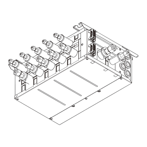
Page 9: Outlines And Dimensions
OUTLINES AND DIMENSIONS unit: mm PAC-MK50BC SUSPENSION BOLT PITCH SUSPENSION BOLT : W3/8(M10) REFRIGERANT PIPE FLARED CONNECTION TO OUTDOOR UNIT LIQUID PIPE 1/4F 1/4F 1/4F 1/4F 1/4F 3/8F GAS PIPE 3/8F 3/8F 3/8F 3/8F 1/2F 5/8F TERMINAL BLOCK TO M-NET UNIT... -
Page 10: Wiring Diagram
2 Turn off for three sec. 3 Repeat 1 to 2. *2 LED on Branch box controller board for service <Symbols used in wiring diagram> *3 D and E for PAC-MK50BC only. : Terminal block, : Connector <Combination of indoor units>... -
Page 11: Necessary Conditions For System Construction
NECESSARY CONDITIONS FOR SYSTEM CONSTRUCTION 6-1. TRANSMISSION SYSTEM SETUP OCH574... -
Page 12: Refrigerant System Diagram
6-2. REFRIGERANT SYSTEM DIAGRAM ■ ■ PAC-MK50BC PAC-MK30BC Thermistor (TH-A–E) Thermistor (TH-A–C) (Gas pipe temperature) (Gas pipe temperature) LEV A–E LEV A–C (Linear expansion valve) (Linear expansion valve) Strainer Strainer #100 #100 Strainer Strainer #100 #100 Capillary Capillary tube tube... - Page 13 6-3. TYPICAL CONTROL SYSTEM TB3A TB3A TB15 OC : Outdoor unit Branch Box A-IC MA-RC (01) M-IC : M-NET Control indoor unit (City Multi indoor unit) (51) A-IC : A-control indoor unit (M, P, S series indoor unit) TB3A TB15 TB3B M1 M2 S M1 M2 S A-IC MA-RC : MA Remote controller MA-RC (02) WL-RC : Wireless Remote controller TB3C TB15 TB3A A-IC MA-RC (03) TB3D TB3A A-IC WL-RC (04) TB3E TB3A...
- Page 14 ( 5) Group setting 1 MA group or M-NET group setting cannot be set. (6) Restricted functions The following functions of system controller cannot be used. • DIDO controller (Interlock with the air conditioner) • Fan control of energy saving control or peak cut control function • Air conditioning charge [TG-2000A] • Set temperature range limiting function • Operation mode changeover limit (season changing) [PAC-SF44SRA] • Dual set point function OCH574...
-
Page 15: Troubleshooting
TROUBLESHOOTING 7-1. HOW TO CHECK THE PARTS BRANCH BOX : PAC-MK50BC PAC-MK30BC Parts name Check points Disconnect the connector then measure the resistance with a tester. Thermistor (TH-A–E) (At the ambient temperature 10 to 30:) <Gas pipe> Normal Abnormal 4.3 to 9.6k"... - Page 16 Linear expansion valve (LEV) in Branch box (1) Operation summary of the linear expansion valve • Linear expansion valve open/close through stepping motor after receiving the pulse signal from the branch box controller board. • Valve position can be changed in proportion to the number of pulse signal. <Connection between the branch box controller board and the linear expansion valve> branch box controller board 12V DC Drive circuit Blue Orange Yellow White Connector LEV-A LEV-B LEV-C LEV-D LEV-E <Output pulse signal and the valve operation> Output Output (Phase) Opening a valve : 8 → 7 → 6 → 5 → 4 → 3 → 2 → 1 → 8...
- Page 17 (3) How to attach and detach the coil of linear expansion valve <Composition> Linear expansion valve is separable into the main body and the coil as shown in the diagram below. Main body Coil Lead wire Stopper <How to detach the coil> Hold the lower part of the main body (shown as A) firmly so that the main body does not move and detach the coil by pulling it upward. Be sure to detach the coil holding main body firmly. Otherwise pipes can bend due to pressure. <How to attach the coil> Hold the lower part of the main body (shown as A) firmly so that the main body does not move and attach the coil by inserting it downward into the main body. Then securely attach the coil stop- per to pipe B. (At this time, be careful that stress is not added to lead wire and main body is not wound by lead wire.) If the stopper is not firmly attached to pipe B, coil may be detached from the main body and that can cause defective operation of linear expan- sion valve.
- Page 18 Troubleshooting Check point Corrective measure Problem Locked expansion Replace the linear If the linear expansion valve becomes locked and the motor is still operating, valve expansion valve. the motor will emit a clicking noise and will not function. This clicking noise indicates an abnormality.
- Page 19 7-2. TEST POINT DIAGRAM Branch box controller board PAC-MK50BC PAC-MK30BC TH-A to E Connect to LEV-A to E Thermistor-A to E Connect to LEV-A to E TH-D and E for PAC-MK50BC only LEV-D and E for PAC-MK50BC only CN3M Connected to the terminal block (TB5) (M-NET transmission con- necting wire) 24–30 V DC (non polar) LED1,LED2 ·Start-up Main power supply (220/230/240 V AC) ·Normal operating LED1:Main power supply LED2:Blink depend on the total number of indoor units. <Example> The total number is 2, 1Blink 2 times 2Turn OFF for 3 seconds 3Repeat 1–2 Mode selection SW12 Address setting 10ths DIGIT SW11 Fuse 6.3 A 250 V...
- Page 20 7-3. INTERNAL SWITCH FUNCTION TABLE ■ The black square ( ) indicates a switch position. OCH574...
- Page 21 7-4. BRANCH BOX UNIT OPERATION MONITOR FUNCTION <Branch box unit operation monitor function> [When option part ‘A-Control Service Tool (PAC-SK52ST)’ is connected to branch box controller board (CNM)] Digital indicator LED1 displays 2 digit number or code to inform operation condition and the meaning of check code by controlling DIP SW2 on ‘A-Control Service Tool’. <Table1> SW5 setting The black square (■) indicates a switch position. SW5 setting Detail Common Operation indicator: 2 3 4 5 6 • SW2 - Use to set the displayed item • SW5 - Use to set the displayed unit Indoor-A...
- Page 22 The black square (■) indicates a switch position. SW2 setting SW5 setting* Display detail Explanation for display Unit ― ― Common Not used Individual unit Actual opening pulse 0 to 500 of LEV (When it is 100 pulse or more, it displays a hundredth, 2 3 4 5 6 (Direct-operated tens, and unit digit by turns.) conversion value) Example: 0 to 500 Pulse When 150 pulse, 0.5 sec 0.5 sec 2.0 sec Common Not used ― ― Individual unit Error history Displays a check code, and M-NET address of the unit which the check code was detected. 2 3 4 5 6 Example: Code If the check code 2520 is detected in the address3,...
- Page 23 The black square (■) indicates a switch position. SW2 setting Display detail Explanation for display Unit SW5 setting* ― ― Common Not used Individual unit Indoor thermistor −39 to 88 [−38 to 190] <pipe temperature/ 2 3 4 5 6 (When the temperature is 0: or less, "−" and temperature 2-phase> (TH5) are displayed by turns.) [-F]* Example: When −5:, 0.5 sec 0.5 sec 2.0 sec − Common Not used ― ― Individual unit −42 to 91 [−43 to 196] Branch box pipe thermistor (TH-A, B, C, (When the temperature is 0: or less, "−" and temperature 2 3 4 5 6 D, E) are displayed by turns.) [-F]*...
-
Page 24: Disassembly Procedure
DISASSEMBLY PROCEDURE BRANCH BOX : PAC-MK50BC PAC-MK30BC PHOTO : PAC-MK50BC OPERATING PROCEDURE PHOTOS Photo 1 1. Removing the controller cover and under panel (1) Remove 3 controller cover fixing screws (4 o 10) to detach Under panel fixing screws the controller cover. (See Photo 1) (2) Remove 4 under panel fixing screws (4 o 10) to remove the under panel. (See Photo 1) Controller cover fixing screw Under panel Controller cover Controller cover fixing screws 2. Removing the thermistor (TH-A–E*) Photo 2-1 Pipe box (under) fixing screws (1) Remove the controller cover. (See Photo 1) - Page 25 OPERATING PROCEDURE PHOTOS Photo 3 3. Removing the LEV coil (LEV-A–E*) (1) Remove the controller cover. (See Photo 1) Bands Rubber mount Header assy (2) Remove the under cover. (See Photo 1) LEV assy Bands (3) Remove 8 insulations, then remove 9 pipe cover fixing screws (4 x 10). (See Photo 2-1) (4) Cut the bands that fixes the lead wire, then pull out the LEV coil(s) (LEV-A – E*). (See Photo 3) (5) Loosen the insulation sheet which bundles the LEV lead wires. (6) Loosen the side clamps, then disconnect the connector(s) on the controller board. (7) Pull out the lead wire(s) through the hole to the controller board side. (See Photo 2-2 or 2-3) *LEV-A–C for PAC-MK30BC. (See Photo 2-3) LEV coil Photo 4 4. Removing the controller board (1) Remove the controller cover. (See Photo 1) Controller board Controller board holder...
- Page 26 OPERATING PROCEDURE PHOTOS 5. Removing the LEV assy Photo 5-1 (1) Remove the controller cover. (See Photo 1) LEV assy (2) Remove the under panel. (See Photo 1) (3) Remove 8 the insulations, then remove 9 pipe cover fixing screws (4 x 10). (See Photo 2-1) (4) Loosen the side clamps, then disconnect the LEV connec- tors on the controller board. (5) Pull out the lead wires through the hole to the controller board side. <Removing the header assy> (6) Cut the band which fixes the header assy and LEV assy together, then remove the rubber mount. (See Photo 3) (7) Remove the header assy. (See Photo 5-1) <Disassembling the pipe box> (8) Remove 2 side panel fixing screws (4 x 10). (See Photo 5-1) (9) Pull out the pipe box (top) and separate it from the side panel. (See Photo 5-2) (10) Turn the pipe box (top) upside down. (See Photo 5-3). Side panel fixing screws (11) Remove 5 insulations, then remove 5 pipe box (top) fixing screws (4 x 10). Photo 5-2 (12) Turn the pipe box (top) upside down again, facing the pipe side up.
- Page 27 OCH574...
- Page 28 HEAD OFFICE : TOKYO BLDG., 2-7-3, MARUNOUCHI, CHIYODA-KU, TOKYO100-8310, JAPAN cCopyright 2014 MITSUBISHI ELECTRIC CORPORATION Distributed in Sep. 2014 No.OCH574 New publication, effective Sep. 2014 Made in Japan Specifications are subject to change without notice.
Need help?
Do you have a question about the PAC-MK50BC and is the answer not in the manual?
Questions and answers