Table of Contents
Advertisement
Quick Links
Download this manual
See also:
User Manual
Advertisement
Table of Contents

Related Manuals for Bentel Omnia


Summary of Contents for Bentel Omnia
-
Page 1: Installation Manual
Omnia/S DAT n. U0805 INSTALLATION MANUAL ®... - Page 2 Installation of these systems must be carried out strictly in accordance with the instructions de- scribed in this manual, and in compliance with the local laws and bylaws in force. The above mentioned Omnia/S has been designed and made to the highest standards of quality and per- formance.
-
Page 3: Table Of Contents
Dialler Telephone Numbers ....41 Omnia 2.1 ......10 Messages . - Page 4 Stop Alarm by key/card ....87 Operations ......75 Expandable Multifunction Control Panel Omnia...
-
Page 5: Introduction
The VectorBPI employs more resources (zones) than VectorBRIDGE. Refer to the VectorBRIDGE and Vector- BPI Instruction Manuals for further details. Programming The system can be programmed via keypad, or via the Bentel Security suite software applications. The software applications greatly enhance all the system features, and provide Customer Database Management and real-time Supervision facilities (via connection to RS232 interface, or Teleservice). -
Page 6: The Omnia Panel
Centronics or RS232 parallel printer interface The Omnia Panel Basic Panel The basic system comprises a Main unit and a keypad. Omnia is available in the following models: Omnia ---- 8 Zones----expandable to 80 with 1.5 A linear battery and keypad. -
Page 7: Technical Specifications
BENTEL Security The BENTEL Security Suite (runs under Windows™ environment) is an indispensable enhancement tool that pro- Suite vides an extremely flexible way of optimizing the performance of the system. B-Mod modem The B-MOD modem and relevant software application can manage manual and automatic teleservice communi- cations, and allow the installer to keep the computer buffer updated. -
Page 8: Accessories
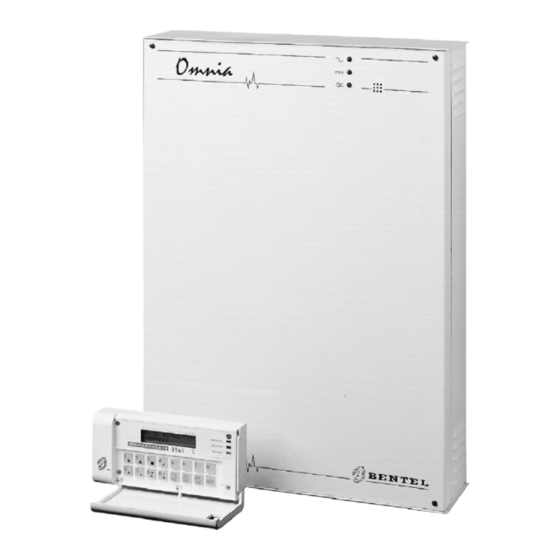
Teleservice and remote monitoring modem CVSER/9F9F ---- Serial cable for computer connection ADSER/9M25F ---- 25-pin adapter for serial ports SECURITY SUITE Bentel Security Suite BXM12/30 3 A remote power-station BXM12/50 ---- 5 A remote power-station VECTORBRIDGE-K ---- Universal Wireless Kit... - Page 9 1 2 3 4 Figure 1 The Omnia system...
-
Page 10: Update
Update The following tables shows "where to look" for information on the various features of the Omnia Panel types. SECTION page Paragraph ......page Sub-paragraph 1 . -
Page 11: Description Of Parts
DESCRIPTION OF PARTS This section describes the main parts of the system, and the meaning of the ON/OFF status of the LEDs. The numbers in boldface (in the Figures) refer to the descriptions in the tables. The white numbers (in the Figures) refer to the common hardware parts of BPI peripherals, therefore, are not described repeatedly. - Page 12 24 External Peripheral power terminals (13.8 V 25 Mains voltage connection terminals (230 V / 50 Hz) Power supply fuse: Omnia = F 250 mA 250V OmniaS = F 2A 250Vfuse 27 Battery plugs 28 Plastic rivet (to be removed when opening the switching-power supply)
-
Page 13: Keypad
Keypad ICON MEANING Partitions armed Alarm memory Trouble and Zone in Test status Not operative with this Panel Open Panel Tamper line alarm Device tamper False key/card at reader Device not found Teleservice enabled Answering device enabled Telephone line engaged PARTS DESCRIPTION 30 Box screws (4)LEDs window... - Page 14 34 Terminal board 35 Tamper switch (2) Snatch switch (accessory item for MIA-S: art. ASNC). The Omnia and Omnia/S Panels comply with IMQ Level 11 certification. MIA-S keypads must be equipped with snatch switches, in order to retain this level.
-
Page 15: Readers
Readers PARTS DESCRIPTION 51 Anchor screw holes (2) 52 Connection cable: red = +; white = C; blue = R; black = - 53 Terminal board 54 Command button 55 Sensitive field 56 Frontplate Screws 57 Key slot 58 Tamper switch (This system is unable to manage the PROXI reader tamper switch) 59 Snatch switch 60 Snatch bracket hole 61 Cable entry... -
Page 16: Input And Output Expanders
65 66 65 66 68 65 69 64 69 64 69 64 69 6468 Figure 7 Input/Output Expander Parts: Omnia4IN (a) M-IN/6 (b) Omnia4OUT (a) M-OUT/6 (b) 74 65 Figure 8 Module and Expander Box Expandable Multifunction Control Panel Omnia... -
Page 17: Installation
Step 5 Pull the connection wires through the hole 38 then attach the backplate and snatch bracket to the wall. 39 40a 41 40a 39 38 40a 41 39 40a Figure 9 Installing the keypad: Omnia TAST (a); MIA-S keypad (b) INSTALLATION... - Page 18 Step 5 Pull the connection wires through the wire entry then attach the backplate and snatch bracket. Position the snatch switch as per Figure 11----for Wall and Flush mounting. Figure 10 Flush mounting reader (a); Wall mounting reader (b) Expandable Multifunction Control Panel Omnia...
- Page 19 Step 6 Replace the PCB. Step 7 Assign the expander Address, set the BPI Level (for M-IN/6 and M-OUT/6 only), then complete the connections on the terminal board 63 (refer to the Connecting BPI Peripherals section for instructions). Step 8 Remove the jumper 64 to enable the tamper and snatch switches. Step 9 Using the jumper 68, set the Output-expander buzzer mode.
- Page 20 83 Voice board (OmniaVOX) 84 Battery 12 V - 17 Ah maximum 85 Power Supply Unit 86 Expanders (Omnia4IN, M-IN/6, Omnia4OUT, M-IN/6, Omnia4R): maximum 3 87 Printer Interface - Scheduler (OmniaTIMER) 88 Speaker Figure 12 Maximum configuration Expandable Multifunction Control Panel Omnia...
-
Page 21: Terminal Board Description
The numbers in round brackets refer to the following notes. (1) The total current draw of Panel terminals [+F], [+B], [+], [+A] and [+N] should not exceed: ---- 2 A for Omnia/S ---- 1 A for Omnia (2) 13.8 V is present on the [+] terminals of the Panel----protected by fuse 18 for the BPI1----and fuse 19 for BPI2. This voltage will be supplied by the battery in the event of Mains failure. -
Page 22: Bpi Peripherals
The input zone and open-collector-output terminals----shown in the diagrams----can be found on the Panel and on the expanders. Each schematic diagram shows the relevant terminals only. The negative terminals may be represented by or --. Expandable Multifunction Control Panel Omnia... -
Page 23: Connecting Bpi Peripherals
Split Section The Omnia and Omnia/S BPI Bus has two independent sections----one consisting of terminals 22, 23, 24 and 25 BPI Bus and the other of terminals 18, 19, 20 and 21. Each section has its own protection fuse, and trouble circuit there- fore, trouble on one section will not impair the other. -
Page 24: Bpi Bus Wiring Limitations
Refer to the VectorBRIDGE and VectorBPI Installation Manuals for the BPI Level of wireless devices. The Omnia/S supports 5V and 12V BPI Level standards. The BPI Level of Omnia/S can be set by means of jumper 11, as shown in the following table. - Page 25 The following terminals supply the sensors: ---- [+F] (positive) and [ ] (negative) on Omnia and Omnia/S ---- [+F] (positive) and [ ] (negative) on Input Expanders ---- [+] (positive) and [ ] (negative) on Keypads Each zone supports several sensors, however, if only one is connected per zone, it will be possible to identify the zones in the event of alarms.
-
Page 26: Connecting Fire Sensors
Refer to Tamper Terminal for the connection of the A.S. terminals. Connecting Fire sensors The Academy40 can manage fire sensors with alarm-repeat outputs that operate at 12 V (e.g. BENTEL SECU- RITY sensors RT101-RT102 and RF501). Refer to Figure 20 for the connection schematic. -
Page 27: Connecting Signalling Devices
Panel terminals [NA1--NC1--C1] and [NA2--NC2--C2] can activate all types of signalling devices. The Panel and Output Expanders have Open-Collector outputs (terminals [OC1] and [OC2], etc.) that can activate Negative alarm line devices directly, and all types of signalling devices through Omnia/4R Relay board. IMPORTANT In order to comply with IMQ Security System Regulations----relays must be connected to the Open-Collector outputs. -
Page 28: Connecting The Power Supply
Omnia is powered by a mains voltage of 230V/50 Hz through an on-board linear power supply. Omnia/S is powered by a mains voltage of 230V/50 Hz through a switching power supply inside the cabinet. The backup battery will supply power in the event of Mains Failure. -
Page 29: Programming
PROGRAMMING This Panel can be programmed via computer or keypad. The Omnia application----from the optional Security Suite software----provides a trouble-free way of programming the Panel. This section holds in-detail information on the system parameters, and should be referred to when programming via keypad. -
Page 30: Customer Data
The Customer code----entered on the Customer data page----will be copied automatically onto the Teleservice page, and vice versa. Panel type Select Omnia for Omnia and Omnia/S. Firmware Release This is a non-modifiable field that will show the selected firmware release (selected from the Options menu or downloaded from the Panel). -
Page 31: Configuration
Configuration On initial Startup the Panel will perform an auto-configuration cycle. The configuration learned during this cycle will become the recognized BPI Bus configuration (refer to the Con- necting the Power supply section). Any changes must be made by the Installer. Proper functioning of the Panel depends on the BPI Bus configuration. -
Page 32: Readers
Config. page and can be used as the device placement identifier. Device Shows the address of the device the zone is assigned to (addresses 1 through 8 for keypad zones; and addresses 1 through 16 for Input-Expander zones). Ter. Shows the zone terminal acronym. Expandable Multifunction Control Panel Omnia... -
Page 33: Zone Programming
Description Shows the zone label (maximum 16 characters)----used as the zone identifier in all parts of the program, and also in the event buffer. Partition Shows the partition the zone is assigned to----Command zones will be indicated by an asterisk. Zone programming To program zone parameters: Select the required zone from the Zone table----the zone number will appear in a box on the top right of the page. -
Page 34: Attributes
Normally closed The zone terminal must be connected to ground during standby status. An alarm will be generated when the zone opens (floating). IMPORTANT If zones are programmed as Normally closed, the Performance Class of the Omnia and Omnia/S Panels will be downgraded from Grade II II to grade, as the zones will not be protected against short-circuits. -
Page 35: Cycles
Cycles This parameter determines the number of times the zone will signal an alarm status before being bypassed on the analysis, as per the following values. Enter the required number of cycles under Cycles. 0 Violation on the zone will be ignored. 1 ÷254 The zone will signal alarm status, as per programming, the zone will then be bypassed on the analysis until one of the following conditions occurs: Status change on its partition... -
Page 36: Outputs
----two 3 A relays (Terminals [NA1], [NC1], [C1], [+A1], [+N1]) and [NA2], [NC2], [C2], [+A2], [+N2]) The Omnia/OUT expanders have four 0.15 A open-collector outputs (Terminals [OC1], [OC2], [OC3] and [OC4]). The buzzer on board the Omnia/OUT expander can be connected to terminal [OC4] with positive or negative logic----depending on the jumper 68. -
Page 37: Reserved Outputs (Manual)
Reserved Outputs (manual) The outputs can be used to switch ON/OFF electrical appliances, from a remote keypad or via telephone. Reserved outputs cannot be assigned to events, and therefore, their status will be determined by the commands given via keypad or telephone. Reserved outputs should not be programmed as Monostable----as they must be activated/stopped manually. -
Page 38: Partitions
Dependent partitions will disarm automatically when one of the partitions they depend on disarms. The Dependent partition can be armed/disarmed manually by enabled User Codes/Keys/Cards. A partition should not be programmed as depending on itself. Figure 25 Partitions page Expandable Multifunction Control Panel Omnia... -
Page 39: Telephone
The Panel will answer after the programmed number of Rings, unless the Double call option is enabled. Enable answer Omnia 2.0 and successive releases do not have this option, as the enable/disable answer option is for the User only. Double Call The Double Call option allows the Panel to share the telephone line with another answering device (answerphone, fax, etc.). -
Page 40: Dialling Mode
DTMF tone Enter how long (in seconds) the Panel must wait, after code acceptance, for the communication to start. If no tele- timeout phone button is pressed within the specified time Panel will end the call. Expandable Multifunction Control Panel Omnia... -
Page 41: Dialler
Dialler Up to 32 Dialler actions can be programmed. The programmed actions can be assigned to the events in the Event-Actions page. Each Dialler action will send a Voice message to signal the start/end of the corresponding event. Refer to Dialler in the FACILITIES section for further details on Dialler programming. Each telephone dialler action can send one of the 14 Voice Messages to up to 16 telephone numbers (selected from the 32 programmable numbers). -
Page 42: Messages
----open the Events-Actions page to view the actions activated by each selected event. Digital Communicator Up to 256 actions can be programmed on the Digital Communicator page, Each action will communicate the start/end of an event to the Central Station. Figure 28 Voice message page Expandable Multifunction Control Panel Omnia... -
Page 43: Digital Communicator
Each Digital Communicator action can send the corresponding event code (event identifier) to up to 4 telephone numbers. Therefore, it possible to signal burglary to the Central Station, fire to the Fire Station, Fault to the In- staller and send emergency requests to the Service Centre. Each event can be assigned to 2 Digital Communicator actions (2 different codes can be assigned to each event). -
Page 44: Actions
All If Yes is selected all the programmed telephone numbers will be dialled, if not, dialling will stop after one success- ful call. Description Enter the label of the Digital Communicator action (maximum 16 characters). Expandable Multifunction Control Panel Omnia... - Page 45 Contact ID Click Contact ID (right side of the Digital Communicator actions window) to program standard events and codes in the Digital Communicator actions window, and in the Events-Action page. Central Stations using Contact ID protocol will receive the event codes shown in the following table. EVENT CODE Alarm on zone...
-
Page 46: Teleservice
Teleservice The B-MOD or B-MOD/RX modem, and the Omnia application from the Security Suite will allow the Installer to teleservice Omnia Panels (e.g. change parameters via telephone). The Teleservice call can be made by: the Installer (with user authorization); the User and the Test event (if en- abled). -
Page 47: Event-Actions
Event-Actions The Events-Actions page is the core of the System. The Panel will operate in accordance with the programming done in this page. Events Table The Output, Digital Communicator and Dialler Actions can be assigned to the Events shown. The Events Table is set out in the following way: no. -
Page 48: Actions
If an alarm event is assigned to a Monostable output (Siren) with a 3-minute On time, the 3-minute cycle will run its full time, even if the cause of alarm has been cleared. However, the Alarm Event will end immediately if the Panel is disarmed. Expandable Multifunction Control Panel Omnia... - Page 49 The ENDS WHEN... column in the following table is valid for events that are not assigned to monostable outputs. Zone events EVENT OCCURS WHEN ... ENDS WHEN ... Alarm on ... the zone is in alarm status ... the zone returns to standby status zone no.
-
Page 50: Generic Events
... the mains power supply is restored mains failure (refer to Filter times in the Programming menu) Warning low ... mains power failure and insufficient battery power for ... the battery charge is above the safety limit battery Panel functioning Expandable Multifunction Control Panel Omnia... - Page 51 EVENT OCCURS WHEN ... ENDS WHEN ... Warning ... the battery is unable to supply the Panel properly ... the battery or the protection fuse 27 is replaced power trouble (calculated with mains present only). Warning ... the power supply of one of the Power stations on mains failure ...
-
Page 52: Spot Events
... an action fails on the DTMF communicator---- Communicator programmed to call the Central station with Contact ID action protocol Failed Dialler ... an action fails on the telephone dialler action Failed Digital Communicator ... a Digital Communicator action fails action Expandable Multifunction Control Panel Omnia... -
Page 53: Dtmf Communicator (For Firmware Versions Lower Than 3.0)
DTMF communicator (for Firmware Versions lower than 3.0) The DTMF communicator (for Firmware versions lower than 3.0) can transmit 8 events----plus 1 of the events man- aged by the Panel----to Central Stations that support this protocol. If the status of a programmed event changes, the Panel will call the enabled telephone numbers (refer to Enable), and will send the assigned Customer code. -
Page 54: Test Event
Proper programming of events and outputs eliminates trouble linked with access control and/or limitations (refer to the Recognition of multiple codes section in the FACILITIES section). Figure 33 Test Event page Expandable Multifunction Control Panel Omnia... -
Page 55: Code Attributes Programmed By The Installer
Code attributes programmed by the Installer The attributes determine how the User code can operate the system (refer to Enable on Partitions----Enable user menu ----Enable instant actions). Available Only Available User codes can operate the system. The system usually requires less than the 31 User codes provided. This time-saving option allows the Installer to make only the required number of User codes Available to operate the system. - Page 56 * The last 3 actions (*1, *2 and *3) are provided by DTMF commands via telephone. Refer to the TELEPHONE OPERATIONS section in the USER MANUAL under: ----Enable/Disable via DTMF and Inputs status via DTMF for *1 and *2; ----Remote Listen-in----Telephone func. for *3. Expandable Multifunction Control Panel Omnia...
-
Page 57: Programming Access Codes
User codes 25 through 31 are enabled for these options (OmniaVOX module required). If a User code is enabled for Scheduler management----the User Menu will provide the Overtime request option, thus allowing the User to delay the programmed arming time. If the code is also enabled for Panel reset----the User Menu will provide the Auto-arm En/Dis. -
Page 58: Attributes Programmed By The User
Pins Mismatch The User code PINs are not at default, or have not been loaded. Therefore, the following data will be downloaded: Description Available: if the User code in the Panel memory is disabled (not Active). Enable User menu Enable on partitions Enable instant actions Figure 35 Keypad codes page Expandable Multifunction Control Panel Omnia... -
Page 59: Digital Keys
Keys Select Digital keys from the Programming menu to open the Digital keys window then program as follows. no. This is the identifier number used during key programming via keypad. Description Assign the identifier label to the key in this field (maximum 16 characters). The label will be used as the key identifier. En. -
Page 60: Options
Attempts This is the number of wrong codes allowed before lock out: accepted values 1 through 10. Lock time sec. This is the keypad lock-out time (in seconds): set 9 through 1,800 seconds. Figure 36 Options page Expandable Multifunction Control Panel Omnia... -
Page 61: Scheduler
Scheduler The OmniaTIMER parameters can be programmed via the Scheduler option from the Programming menu (refer to the OmniaTIMER section). LCD strings Select the LCD strings option from the Programming menu to change the Welcome message and language (LCD strings) on the keypads. The Welcome message will be shown in response to valid User code PINs. Change Welcome Enter the new message in the Welcome message space (max. -
Page 62: On-Site Downloading From Computer
DB9 female connector cable connector DB9 female 7 wire shielded DB25 female connector cable connector Figure 37 Diagram of a Serial cable with two DB9 connectors (a) and with a DB9 and a DB25 connector (b) Expandable Multifunction Control Panel Omnia... -
Page 63: Remote Downloading From Computer
The connection status will be shown in the box at the bottom of the Connection management page. The following messages table shows the messages and meanings. Omnia/Norma MODEM v. x.xx This is the modem release connected to the computer serial port. Modem not recognized The modem is not recognized on the selected serial port. Check the cable and the selected serial port (see Serial ports----Options menu). -
Page 64: Programming From Keypad
Event-Actions The following events are addressed to output no. 1: Generic alarm on partition no. The following events are addressed to output no. 2: Tamper alarm on partition no. Tamper on Main unit Balanced tamper Tamper on BPI Peripherals Expandable Multifunction Control Panel Omnia... -
Page 65: A Basic System
False key at reader The following event is addressed to output no. 3: Warning generic The following event is addressed to output no. 4: Trouble on BPI Dialler Action no. 1 sends message no. 1 to the first 16 numbers of the telephone-number list, this action will be gener- ated by the following events: Generic alarm on partition no. - Page 66 The system will arm when the key/card is removed. The red LED on the reader will remain ON. To disarm the system: use a valid key/card at any reader. The red LED will go OFF. The system will disarm when the key/card is removed. The red LED will remain OFF. Stop alarm on To stop siren signalling generated by an alarm zone event: siren...
-
Page 67: Omniavox
OmniaVOX greatly increases the resources of the Omnia system. The OmniaVOX kit comprises a Voice board, Microphone board and Speaker. The recorded voice messages can be assigned to the telephone dialler num- bers, or to the Omnia inputs (for input status control via telephone). They can also be used as answer messages (answering-machine feature). -
Page 68: Expand Listen-In Partitions
4-Output expander----Omnia/4OUT a 4-Input expander----Omnia/4IN two Relay modules----Omnia/4R Omnia must be programmed as follows. All the outputs of the Output expander must be Reserved, Bistable and Normally Open. The Input expander zones must be: ----Instant; Repetitive; Normally Open. -
Page 69: Manual And Auto-Select Mode
VOX-REM VOX-REM Figure 40 Connecting OmniaVOX-MS boards to the Voice board (the example shows the connection of 4 OmniaVOX-MS ) Output exp. 01 Input exp. 01 Omnia/4OUT Omnia/4IN O C 1 O C 1 O C 2 O C 2... - Page 70 103 104 108 109 110 111 112 Figure 42 Parts identification and installation of the OmniaTIMER Expandable Multifunction Control Panel Omnia...
-
Page 71: Omniatimer
When Omnia engages the telephone line (indicated by T above the icon on the keypad)----the Omnia- TIMER will delay the scheduled operations until Omnia hangs up. Scheduled operations will be ignored during the Omnia programming session----or when Omnia is connected to a computer via serial port. General features... - Page 72 5. Plug the parallel printer into the parallel printer connector (106)----or the serial printer into the serial printer connector (103) of the OmniaTIMER. 6. Connect terminals [+12V] and [ ] of the OmniaTIMER to terminals [+B] and ] of the Main unit. Figure 43 Connecting the serial printer to the interface Expandable Multifunction Control Panel Omnia...
-
Page 73: Programming
Programming The Scheduler (see Figure 45) can be programmed to control automatic Arming/Disarming of the 8 partitions (2 arm and 2 disarm operations per partition), and the ON/OFF times of the 8 Timers that can control up to 8 appli- ances (Courtesy lights, Sprinkler system, Heating, etc.). - Page 74 ----00 in the hour field will disable this feature. Summer time This is the Date and the Time of change-over from Standard to Summer time. Printout Enter the Event buffer printout header (maximum 16 characters). header Figure 45 OmniaTIMER programming page Expandable Multifunction Control Panel Omnia...
-
Page 75: Operations
Real-time printout Select this option for real-time events printout----on the printer connected to the printer interface. Select the Print buffer option from the USER menu for a entire Event buffer printout (the last 200 events). WARNING The OmniaTIMER will be disabled during the entire Event buffer printout----which can take several minutes. -
Page 76: Timers
The OmniaTIMER will be reinitialised when the computer connection ends. Operations requested dur- ing disabled status of the OmniaTIMER will be ignored. When Omnia connects to the serial port (CTS LED ON), the OmniaTIMER will be disabled automatically. There- fore, all scheduled operations (arm/disarm partition----enable/disable Timer----printout or entire Event buffer print- out) will be delayed until the serial port is free again. -
Page 77: Facilities
FACILITIES This section describes some of the most frequently used Omnia/S system facilities. Fast arming The connections and programming described in this section will allow users to arm specific partitions (areas), by simply pressing a keypad button. The Fast arming facility can be associated with a Super key event (Events no. -
Page 78: Temporary Disarming (Patrol)
Normally open Normally open Normally open On Time - Sensitivity - Low Sensitivity - Standard - [patrol time + 1] Min. Pulses - 1 Pulse length - - [patrol time] Min. Figure 48 Temporary disarming (patrol) Expandable Multifunction Control Panel Omnia... -
Page 79: Managing Common Partitions
Managing Common Partitions The connections and programming described in this section will allow the system to manage Common partitions. This facility is especially useful in commercial buildings where several offices or rooms are adjacent to a common area, such as corridor. Following is a programming example, that shows how the Panel will arm and disarm partition 5, in accordance with the status of partitions 1, 2, 3 and 4. - Page 80 The signal on output OCx will also be present on outputs OC1, OC2, OC3, ..., OCn with a 2 second delay (ap- prox.). The signal on output OCx must be present for more than 400 mS in order to activate outputs OC1, OC2, OC3, ..., OCn. Figure 50 Multiple output event via Hardware Expandable Multifunction Control Panel Omnia...
-
Page 81: Multi-Output Event (Via Software)
Multi-output events (via Software) The programming described in this section will allow single events to activate several outputs. This procedure makes the fullest use of the hierarchy that is inherent in the events structure. The Generic Alarm event (partition or panel) and Tamper alarm event (partition or panel) both trigger the Ge- neric+Tamper alarm event (partition or panel), as the latter is the sum of the previous two events (see Figure 54). -
Page 82: Recognition Of Multiple Codes
These outputs will stay open for 2 minutes. The three codes must be entered within this interval, otherwise, one of the outputs will close to ground and block input zone [Ly], thus blocking output [OCx] that opens the door. Figure 53 Recognition of multiple codes Expandable Multifunction Control Panel Omnia... -
Page 83: Disarming Under Duress
Disarming under duress The connections and programming described in this section will allow the user to disarm the system and, at the same time, send a Disarming under duress event to the central station. Solution no. 1 Program two codes for partition disarming----the first for use in normal circumstances; and the second for use un- der duress (forced disarming). -
Page 84: Dialler
Dialler The 32 Omnia Dialler actions programmed in the Dialler page can be assigned to events in the Event-Actions page to signal the start and end of an event. All dialler actions will send a Voice message (selected from the 14 recordable messages) to up to 16 Telephone Numbers (selected from the 32 programmable numbers in the Telephone page). - Page 85 ----Action 5 (Flooding Alarm) will send the Flooding message to telephone numbers: 1 (Police Fire Emer); 4 (Head Office); 5 (Branch Office); 6 (Patricia Mobile) and 7 (Patricia Office). Telephone numbers will be dialled in accordance with call priority. The examples show how dialler actions operate. However, they must be assigned to one or more events in order to activate actions.
- Page 86 With reference to the examples----actions 5 and 6 are assigned to 24h alarm on partition 1 (Warehouse) and Warning fuse +B events respectively. Select Events on the Dialler actions page to view the events that will generate the selected Dialler action. Expandable Multifunction Control Panel Omnia...
-
Page 87: Stop Alarm By Key/Card
Stop Alarm by Key/Card The connections and programming described in this section will allow the user to stop Outputs (Horns, Strobes, etc.) and calls, by using a valid key/card at a enabled reader (enabled on the partition in Alarm status). This facility is espe- cially useful in the event of false alarms. - Page 88 BENTEL SECURITY s.r.l. C.da Ravigliano, Z.I. S.Scolastica 64013 CORROPOLI (TE) - ITALY Tel.: +39 0861 839060 Fax: +39 0861 839065 e-mail: info@bentelsecurity.com http://www.bentelsecurity.com ISTOMNIAINS-UK 4.1 020703 V4.2...
Need help?
Do you have a question about the Omnia and is the answer not in the manual?
Questions and answers