Table of Contents
Advertisement
Quick Links
Download this manual
See also:
Instruction Manual
SERVICE MANUAL
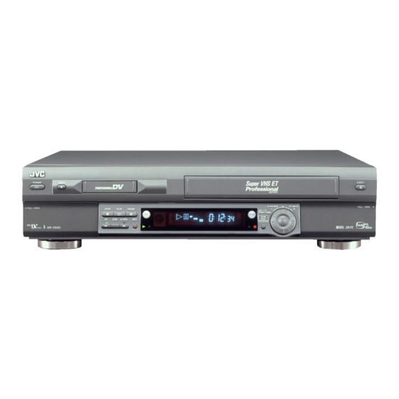
Mini DV/S-VHS VIDEO CASSETTE RECORDER
TV
CABLE/SAT
1
LCD PROG
2
1
4
VPS/PDC
7
0000
1
PROG
2
START
DEBUT
SPECIFICATIONS
GENERAL
Power requirement : AC 220 V - 240 V
Power consumption
Power on
: 31 W
Power off
: 6.5 W
Temperature
Operating
:
5°C to 40°C
Storage
:
–20°C to 60°C
Operating position : Horizontal only
Dimensions (WxHxD)
: 435 mm x 106 mm x 380 mm
Weight
: 5.1 kg
Input/Output
: 21-pin SCART connectors:
IN/OUT x 1, IN/DECODER x 1
RCA connectors:
VIDEO IN x 1, AUDIO IN x 1,
AUDIO OUT x 1
S-Video connectors:
IN x 1, OUT x 1
DV connector:
IN/OUT x 1 (4-pin, IEEE1394
conformity, digital input/output)
VHS DECK VIDEO/AUDIO
Signal system
: PAL-type colour signal and CCIR
monochrome signal, 625 lines
50 fields
Recording system : DA4 (Double Azimuth) head helical
scan system
Format
: S-VHS/VHS PAL standard
Signal-to-noise ratio: 45 dB
Horizontal resolution
(SP/LP)
: 250 lines (VHS)
400 lines (S-VHS)
Frequency range
: 70 Hz to 10,000 Hz (Normal audio)
20 Hz to 20,000 Hz (Hi-Fi audio)
Maximum recording time
(SP)
: 240 min. with E-240 video cassette
(LP)
: 480 min. with E-240 video cassette
SR-VS30E/EK
DV
VHS
AUDIO
– –:– –
TV/VCR
2
3
5
6
3
DAILY/QTDN.
WEEKLY/HEBDO
8
9
4
4
AUX
MENU
0
ENTER/ENTREE
OK
30 SEC
3
STOP
DATE
PR
FIN
EXPRESS
PULL-OPEN
TIRER-OUVRIR
DV
DV
DUB
VHS
COPIE
(The specifications shown pertain specifically to the model SR-VS30E.)
, 50 Hz/60 Hz
d
This service manual is printed on 100% recycled paper.
COPYRIGHT © 2002 VICTOR COMPANY OF JAPAN, LTD
PULL-OPEN
PR
/ +
TIRER-OUVRIR
PUSH / TURN
VHS
24H
EXPRESS
1
3
2
DV DECK VIDEO/AUDIO
Signal system
: PAL-type colour signal, 625 lines
50 fields
Recording system : Digital Component Recording
Format
: DV format (SD mode)
Cassette
: Mini DV Cassette
Maximum recording time
(SP)
: 80 min. with M-DV80ME cassette
(LP)
: 120 min. with M-DV80ME cassette
Audio recording system
: PCM 48 kHz, 16 bit (2 ch)/
32 kHz, 12 bit (4 ch)
TUNER/TIMER
TV channel storage capacity
: 99 positions (+AUX position)
Tuning system
: Frequency synthesized tuner
Channel coverage : VHF 47 MHz – 89 MHz/
104 MHz – 300 MHz/
302 MHz – 470 MHz
UHF 470 MHz – 862 MHz
Memory backup time
: Approx. 10 min.
ACCESSORIES
Provided accessories
: RF cable,
21-pin SCART/RCA cable,
BNC/RCA adapter x 2,
Satellite Controller,
Infrared remote control unit,
" R6" battery x 2
Specifications shown are for SP mode unless otherwise specified.
E.& O.E. Design and specifications subject to change without
notice.
625
SR-VS30E/EK
V14SD1
No.82910
March 2002
Advertisement
Table of Contents

Related Manuals for JVC SR-VS30E


Summary of Contents for JVC SR-VS30E
- Page 1 TIRER-OUVRIR TIRER-OUVRIR PUSH / TURN EXPRESS COPIE SPECIFICATIONS (The specifications shown pertain specifically to the model SR-VS30E.) GENERAL DV DECK VIDEO/AUDIO Power requirement : AC 220 V - 240 V , 50 Hz/60 Hz Signal system : PAL-type colour signal, 625 lines...
-
Page 3: Table Of Contents
2.10 MECHANISM PHASE CHECK/ADJUSTMENT ......2-35 LOADING MOTOR BOARD ASSEMBLY <55> ........5-27 2.11 MECHANISM DISASSEMBLY/ASSEMBLY SHEET ..... 2-36 JOG BOARD ASSEMBLY <85> ............5-27 The following table lists the differing points between models SR-VS30EK and SR-VS30E. MODEL SR-VS30EK SR-VS30E... -
Page 4: Important Safety Precautions
Important Safety Precautions Prior to shipment from the factory, JVC products are strictly inspected to conform with the recognized product safety and electrical codes of the countries in which they are to be sold. However, in order to maintain such compliance, it is equally important to implement the following precautions when a set is being serviced. - Page 5 Safety Check after Servicing Examine the area surrounding the repaired location for damage or deterioration. Observe that screws, parts and wires have been returned to original positions, Afterwards, perform the following tests and confirm the specified values in order to verify compli- ance with safety standards.
-
Page 7: Disassembly
SECTION 1 DISASSEMBLY 1.1 HOW TO REMOVE THE MAJOR PARTS 1.3 DISCONNECTION OF CONNECTORS (WIRES) 1.1.1 Introduction This set is a double-deck video recorder integrating a Mini DV deck and a VHS deck. Its internal structure is divided into three sections that include the power supply, VHS and DV sections. -
Page 8: How To Remove The Major Parts
1.4 HOW TO REMOVE THE MAJOR PARTS <COM section> [1] Top cover 1.4.1 Disassembly flow chart (S1b) (S1a) This flowchart shows the disassembly procedure for the ex- terior parts and electrical parts. (S1b) Basically, reverse this procedure when assembling them. Top cover, Bracket Front panel assembly SW/Display board assembly, Power SW board assembly,... - Page 9 (S5a) (L5a) [5] Lug wire [2] Front panel assembly (L5d) (L5a) (L5a) Knob (Jog) (L5a) (L5a) Jog board assembly <Note 3a> Power SW board (L5b) (L5c) assembly SW/Display board (S3a) assembly (L5b) (S3a) (S3c) (L5b) (S3c) (S3a) (S3a) (S3a) (S3a) (S3a) (S3a) (S3b)
-
Page 10: How To Remove The Major Parts
1.5 HOW TO REMOVE THE MAJOR PARTS <VHS section> Procedures for Lowering the Cassette holder assembly As the mechanism of this unit is integrated with the Housing 1.5.1 Disassembly flow chart assembly, the holder must be lowered and the two screws un- This flowchart shows the disassembly procedure for the ex- screwed when removing the Mechanism assembly. - Page 11 Note: Note: Make a crease on the position where When installing the the dotted line is not exceeded. Mechanism assembly, (WR7a) A/C head base (L8a) secure the screws CN2601 (S8a) (S7a to S7b) in the CN701 order of a, b. (L8a) CN3014 (WR7a)
-
Page 12: How To Remove The Major Parts
1.6 HOW TO REMOVE THE MAJOR PARTS <DV section> 1.6.1 Disassembly flow chart This flowchart shows the disassembly procedure for the ex- (S9b) terior parts and electrical parts. (S9a) Basically, reverse this procedure when assembling them. However, it is required to remove the common section parts (S9a) as far as [1] “Top cover, Bracket”... - Page 13 (S11a) [3] DV MDA board assembly NOTE: When removing, remove in order of a number (S11a) (S11b) CN5504 Bracket(DV) (S11b) (WR11d) <Note 2c> (WR11a) CN5505 <Note 2c> CN5502 CN5503 CN5507 (WR11b) <Note 2c> (WR11e) <Note 2c> (L11a) (WR11c) <Note 2c> Fig.
-
Page 14: Connection
1.7 CONNECTION right side CN901 CN502 right side TERMINAL PWB Hold wire by stylepin. Treat the wire so as not to come to fan. bend right side right side make a crease right side right side CN3001 right side bend bend CN5323 DRUM... - Page 15 DETAIL "D" DETAIL"A" DETAIL"B" DETAIL"C" DV MDA BOARD ASSEMBLY Absorb the looseness of FRONT the wire in the B part. PANEL BOTTOM CHASSIS DV MAIN DV MECHA DRUM MAIN PWB CN7510 CN3011 CN5504 CN1502 BOTTOM Absorb the looseness of the wire CHASSIS according to the following figure.
-
Page 16: Service Positions
1.8.3 Service position <DV FOIL SIDE> 1.8 SERVICE POSITIONS <Removal> The servicing locations for use in troubleshooting or servic- (1) Remove the top cover and bracket. ing of the set are provided separately for the VHS and DV. (2) Remove the front panel assembly. SERVICE POSITIONS <VHS SIDE>... -
Page 17: Service Position
1.8.4 Service position <DV COMPONENT SIDE> Jig RCU mode <Removal> This unit uses the following two modes for receiving remote (1) Remove the top cover and bracket. control codes. (2) Remove the front panel assembly. 1) User RCU mode : Ordinary mode for use by the user. (3) Remove the Base(DV) together with DV Mechanism as- 2) Jig RCU mode : Mode for use in production and serv-... -
Page 18: Mechanism Service Mode
1.10 MECHANISM SERVICE MODE This model has a unique function to enter the mechanism (5) With lock levers A B on the left and right of the Cassette into every operation mode without loading of any cassette holder assembly pulled toward the front, slide the holder tape. -
Page 19: Emergency Display Function
Notes: 1.11 Emergency display function • The EMG detail information <1><2> show the information This unit has a function for storing the history of the past two on the latest EMG. emergencies (EMG) and displaying them on each FDP (or It becomes “... - Page 20 1.11.3 EMG content description Note: EMG contents “E08/E09” are for the model with Dynamic Drum (DD). CONTENT CAUSE E01: Loading EMG When the mechanism mode cannot be changed to an- 1. The mechanism is locked in the middle of mode transition. 2.
- Page 21 1.11.4 EMG detail information <1> * 2 : Mechanism operation mode [Common table of MN* and M3*] The status (electrical operation mode) of the VCR and the sta- tus (mechanism operation mode/sensor information) of the Display Mechanism operation mode mechanism in the latest EMG can be confirmed based on the MN* M3* figure in EMG detail information <1>...
- Page 22 3– : Mechanism sensor information Note: [Common table of MN*, HD* and M3*] • EMG detail information <2> is the reference information stored using the remaining tape detection function of the Mechanism sensor information Display MN* / HD* cassette tape. As a result, it may not identify cassette cor- REC safety Start S-VHS SW...
-
Page 23: Mechanism Adjustment (Vhs)
SECTION 2 MECHANISM ADJUSTMENT (VHS) 2.1 Before starting repair and adjustment 2.1.1 Precautions (1) Unplug the power cord plug of the VCR before using your Loading motor soldering iron. (2) Take care not to cause any damage to the conductor wires when plugging and unplugging the connectors. -
Page 24: Jigs And Tools Required For Adjustment
2. In case of mechanical failure 2.1.4 Jigs and tools required for adjustment If you cannot remove the cassette tape which is loaded be- Roller driver A/C head positioning tool Torque gauge cause of any mechanical failure, manually remove it by tak- PTU94002 PTU94010 PUJ48075-2... -
Page 25: Maintenance And Inspection
2.1.5 Maintenance and inspection 1. Location of major mechanical parts In this chapter, the two mechanism speeds are described by comparing the speeds of the standard type and the high-speed FF/REW type. It is possible to distinguish between these two types of mechanism by the diameters of their capstan pulleys. The capstan pulley diameter for the standard type is approx. - Page 26 4. Suggested servicing schedule for main components The following table indicates the suggested period for such Guide rail Roller cam assembly service measures as cleaning,lubrication and replacement. In practice, the indicated periods will vary widely according to environmental and usage conditions.However, the indi- cated components should be inspected when a set is brought for service and the maintenance work performed if neces- sary.
- Page 27 Symbols and numbers R4 R1 T9 T12 T11 B15 B12 B14 B13 B17 B21 B7 B8 B5 B4 B11 T14 T15 T13 T22 T24 T18 B19 Removal parts (Reference items) Replacement parts 2.2.3 Guide rail 2.2.3 Roller cam assembly 2.2.3 Cassette housing bracket 2.2.3 Opener guide 2.2.3 Door opener 2.2.3 Relay gear...
-
Page 28: Replacement Of Major Parts
2.2 Replacement of major parts 2.2.3 Cassette holder assembly 1. How to remove 2.2.1 Before starting disassembling (Phase matching (1) Remove the guide rail and roller cam assembly. (See between mechanical parts) Fig.2-2-3a.) The mechanism of this unit is closely linked with the rotary (3 lugs on the guide rail and one lug on the roller cam encoder and system controller circuits. - Page 29 (5) While holding the left side of the cassette holder, lift the 2. How to install (Phase matching) cassette holder assembly so that the three legs on the (1) Insert the section (A) of the drive arm into the section (B) left side are all released.
-
Page 30: Pinch Roller Arm Assembly
2.2.6 A/C head Notches Guide hole Notch 1. How to remove Relay gear (1) Remove the two screws (A) and remove the A/C head together with the head base. (2) When replacing only the A/C head, remove the three screws (B) while controlling the compression spring. Head base Screws(A) Drive gear... -
Page 31: Capstan Motor
2. How to install (Centering the mounting position) Loading motor board assembly When the capstan motor has once been removed and then reinstalled out of the initial correct position in the rotational Loading motor direction, the capstan motor current may be unstable during Lugs operation in high or low temperatures. -
Page 32: Rotary Encoder
2.2.10 Rotary encoder 2.2.12 Change lever assembly, direct gear, clutch gear and coupling gear 1. How to remove (1) Remove the screw (A) and remove the rotary encoder 1. How to remove by pulling it up. (See Fig. 2-2-10a.) (1) Release the two lugs of the rotary encoder guide in the arrow-indicated direction and remove the change lever assembly. -
Page 33: Link Lever
2.2.13 Link lever 2.2.14 Cassette gear, control cam and worm gear 1. How to remove 1. How to remove (1) Remove the two slit washers. (1) Remove the control cam by lifting it. (2) Remove the link lever by lifting it from the shaft retained (2) Open the two lugs of the cassette gear outward and pull by the slit washers. -
Page 34: Loading Arm Gear (Supply Or Take-Up Side) And Loading Arm Gear Shaft
(3) Install the control plate so that the section A of the load- (3) Turn the loading arm gear (take-up side) clockwise so ing arm gear shaft fits into the hole (A) of the control plate, that the notch of the loading arm gear (take-up side) is the section B of the control plate guide into the hole (B), in alignment with the projection of the loading arm gear and the control plate comes under the section C of the... -
Page 35: Take-Up Lever, Take-Up Head And Control Plate Guide
2.2.17 Take-up lever, take-up head and control plate guide (1) Remove the spring of the take-up lever from the main deck. Spring (2) Remove the lug (A) of the take-up lever from the main Sub brake assembly deck and pull out the take-up lever and the take-up head Lug(A) (take-up side) together. -
Page 36: Tension Brake Assembly, Reel Disk (Supply Side) And Tension Arm Assembly
2.2.21 Tension brake assembly, reel disk (supply side) 2.2.23 Stator assembly and tension arm assembly (1) Remove the flat cable. 1. How to remove (2) Remove the two screws (A), (B) and remove the lug wire. (1) Remove the three lugs of the tension brake assembly (3) Remove the stator assembly by lifting in the arrow-indi- from the main deck and pull them off. -
Page 37: Upper Drum Assembly
2.2.25 Upper drum assembly Notes: • To replace the upper drum assembly only may not be possible with some models. For upper drum assem- bly replacement, refer to the parts list. (When the parts number of the upper drum assembly is not listed on Lower drum assembly the parts list, then this cannot be replaced.) •... -
Page 38: Compatibility Adjustment
2.3 Compatibility adjustment pole base assembly (supply or take-up side). (7) Unload the cassette tape once, play back the alignment Notes: tape (A1) again and confirm the V.PB FM waveform. • Although compatibility adjustment is very important, (8) After adjustment, confirm that the tape wrinkling does not it is not necessary to perform this as part of the nor- occur at the roller upper or lower limits. - Page 39 (4) Adjust the AUDIO OUT waveform and Control pulse waveform by turning the screws (1), (2) and (3) little by little until both waveforms reach maximum. The screw (1) and (3) are for adjustment of tilt and the screw (2) for azi- muth.
- Page 40 [Perform adjustment steps (7) to (10) only for 2 Head (4) Set the VCR to the Auto adjust mode by transmitting the models equipped with LP mode.] code (F) twice from the Jig RCU. When the VCR enters the stop mode, the adjustment is completed. (7) Then play back the alignment tape (A2).
- Page 41 Mechanism Timing Chart EJECT CASS- Mechanism mode CASS-INS FF/REW STOP SLOW/STILL PLAY Control plate mark HIGH C CH HIGH Rotary encoder B CH HIGH A CH Control cam angle 264. 318. 412. Rotary encoder 114. 150. 167. 178. 207. 218. 240.
-
Page 42: Mechanism Adjustment (Dv)
MECHANISM ADJUSTMENT (DV) (5) : Parts to be removed in disassembly/assembly, such as 2.4 PREPARATION screws, washers and springs, and the points. 2.4.1 Precautions (1) Observe the specified screw tightening torque when at- Symbol Name & Point taching parts. The torque should be 0.04 Nm (0.4 kgfcm) unless otherwise specified. -
Page 43: Disassembly/Assembly Of The Mechanism Assembly
DISASSEMBLY/ASSEMBLY OF THE MECHANISM ASSEMBLY 2.5.1 Introduction The disassembly and assembly of the mechanism assem- To set the ASSEMBLY mode, apply 3 V DC to the electrodes bly should usually be performed in the ASSEMBLY mode. on the upper part of the loading motor as shown in Fig. 2-5- (Table 2-5-1) Note that the mechanism is in the cassette in (C-IN) mode when the mechanism assembly is taken out of the set and... - Page 44 2. Setting/checking the ASSEMBLY mode DC 3 V Motor Bracket Assembly (Loading Motor) Wire (Brown) Note: • In this ASSEMBLY mode, only the 2 gear teeth of the rotary encoder are marked (red coloring). Marking Wire (Red) (Colored red) Rotary Encoder <...
-
Page 45: Mechanism Timing Chart
2.6 MECHANISM TIMING CHART See following table (Table 2-6-1). MODE ASSEMBLY LOADING END C-IN S. FF PLAY STOP FF/REW PARTS ROTARY ENCODER ROTARY ENCODER 33.33 166.66 193.33 226.66 273.33 306.66 MAIN CAM SUB CAM POLE BASE S/REV PLAY CTL PLATE FF/REW ON 1 MAIN BRAKE(SUP) -
Page 46: Mechanism Assembly/Disassembly Procedure Table
MECHANISM ASSEMBLY/DISASSEMBLY PROCEDURE TABLE Step Fig. /Loc Part Name Point Note Discription A Cassette housing assembly/ B Mechanism assembly T 2-13-1 2(S1),(L1) – (L5) 1 Drum assembly T 2-13-2 3(S2) 2 Motor bracket assembly T 2-13-2 4(S2) 3 Middle catcher assembly T 2-13-3 3(S2) —... - Page 47 TOP VIEW – Fig. 2-7-1 2-25...
-
Page 48: Disassembly/Assembly
DISASSEMBLY/ASSEMBLY 1. A Cassette Housing Assembly/ B Mechanism Assembly <Note 1a>: If the wires for the cassette housing motor are connected to the circuit board, remove them be- fore disassembly. ( S1 ) ( S1 ) ( L2 ) ( L4 ) ( L5 ) <Note1a>... - Page 49 3. 3 Middle Catcher Assembly/ 4 Reel Cover Assembly <Note 3a>: Once the reel cover assembly has been re- moved, the parts located below it tend to slip out easily: Be careful. <Note 3b>: When attaching these screws, screwing order ( S2 ) a b c .
- Page 50 5. 9 EXIT Guide Arm Assembly/ 10 Swing Arm Assembly <Note 5a>: EXIT Guide Arm Assembly phase alignment. EXIT Guide Arm Assembly This protrusion is <Note5a> combined to the dent of CHARGE ARM ASS'Y. ( W1 ) Charge Arm Assembly Gear alignment EXIT Guide Arm Assembly...
- Page 51 7. 14 Reel disk assembly (Sup) / 15 Reel disk assembly (Take up) / 16 Prism / 17 Control plate ( S2 ) ( L12 ) ( L12 ) Fig. 2-8-7 8. 18 Guide rail (Take up) assembly / 19 Guide rail (Sup) assembly / 20 Base plate assembly <Note 8a>: When attaching, set the alignment markings of the two gears so that the markings face oppo-...
- Page 52 9. 21 Ent. guide base assembly / 22 Worm wheel 2 / 23 Timing belt / 24 Center gear assembly <Note 9a>: How to attach the worm wheel 2 22 . ( S2 ) Phase alignment <Note9a> Mark (Red) Align the phase of the rotary encoder assembly 34 , then attach it by aligning the phase hole of the mecha- nism assembly.
- Page 53 11. 29 Tension control arm assembly/ 30 Brake control arm assembly / 31 Charge arm assembly <Note 11a>: How to attach the tension control arm assem- bly 29 / Brake control arm assembly 30 . ( L16 ) ( W1 ) ( L17 ) <Note11a>...
- Page 54 13. 34 Rotary encoder assembly / 35 Main cam / 36 Arm gear 1 assembly / 37 Centering arm assembly <Note 13a>: How to attach the rotary encoder assembly 34 . Mark (colored : red) ( S2 ) ( S2 ) <Note13a>...
- Page 55 14. 38 Sub cam / 39 Arm gear 2 assembly / 40 Clutch lock lever assembly <Note 14a>: How to attach the sub cam 38 . Boss ( S2 ) <Note14a> Phase alignment Phase alignment <Note14a> Phase alignment <Note14b> ( L19 ) Align the phases of the arm gear 2 assembly 39 and clutch lock lever assembly 40 , then attach them by fitting the boss into the lower cam slot and tighten the...
-
Page 56: List Of Procedures For Disassembly
LIST OF PROCEDURES FOR DISASSEMBLY 14(S3) (W2) (S2) (S2) (S2) (S2) (P3) (W1) 6(S2) 9(S2) (S2) 7(S2) 8(S2) (S2) (S2) (S2) (S2) (S2) (S2) (S2) (S2) (S2) 31(S2) (S2) (S2) (S2) (S2) (S2) (W1) (S2) (S2) (W1) (S2) (S2) ADJ. (W1) (P7) (S2) -
Page 57: Mechanism Phase Check/Adjustment
2.10 MECHANISM PHASE CHECK/ADJUSTMENT See Fig. 2-10-1. Worm Wheel 2 Arm Gear 1 Assembly See Fig. 2-8-9A. See Fig. 2-8-13B. Rotary Encoder Assembly See Figs. 2-8-9A and 2-8-13A. Arm Gear 2 Assembly See Fig. 2-8-14A. Sub Cam See Fig. 2-8-14A. Main Cam See Figs. -
Page 58: Mechanism Disassembly/Assembly Sheet
2.11 MECHANISM DISASSEMBLY/ASSEMBLY SHEET Fig. No. Type Attachin 2-13-1 2-13-2 2-13-3 Ref. Fig. 2-13-4 2-13-6 A Cassette housing assembly Drum assembly 4 Reel cover assembly ( S2 ) ( S1 ) ( S2 ) ( S2 ) ( S2 ) ( S1 ) S2×3 S2, L6×2... - Page 59 2-13-7 2-13-8 2-13-9 2-13-12 2-13-13 2-13-14 2-13-15 7 Band arm plate sub 11 Sub deck assembly 12 Main 13 Main assembly Brake(Sup) Brake(Take up) ( S2 ) assembly assembly ( S3 ) ( P4 ) ( P5 ) ( W2 ) ( S2 ) ( P2 ) ( S2 )
-
Page 60: Positioning The Tension Pole
2.12 POSITIONING THE TENSION POLE See Fig. 2-12-1. B section Tension Arm Sub Assembly D section Screw A Fig. 2-12-1 Adjustment Method Note: • Remove the cassette housing assembly in advance. 1. Set the mechanism mode to the PLAY mode. (See pages 2-20 and 21.) 2. -
Page 61: Compatibility And Error Rate Adjustments
2.13 COMPATIBILITY AND ERROR RATE ADJUSTMENTS 2. Procedure 1. Take out the 6 screws, then remove the top cover. (See Fig. COM1 on page 1-2 of section 1.4.) 2.13.1 Preparation 2. Connect the jig connector cable to CN2001 on the DV Before disassembly and adjustment, back up the data stored MAIN board. -
Page 62: Linearity Adjustment
2.13.3 Linearity adjustment 2.13.4 PB switching point adjustment The following flowchart shows the linearity check/adjustment The following flowchart shows the PB switching point adjust- procedure. ment procedure. Connect an oscilloscope (CH: + Slope) and, while triggering Load the alignment tape. it with the HID signal, observe the ENV OUT waveform. - Page 63 2.14 TAPE EJECTION 3. If the tape is slack, wind it up by turning the shaft on the If a loaded cassette tape cannot be ejected due to a failure topside of the capstan motor in the direction of the arrow in the electrical circuitry, take the cassette tape out using the using a pointed tool (chip IC replacement jig).
-
Page 64: Electrical Adjustment (Vhs)
SECTION 3 ELECTRICAL ADJUSTMENT (VHS) 3.1 Precaution The following adjustment procedures are not only necessary • Set the switches as shown below unless otherwise after replacement of consumable mechanical parts or board specified on the relevant adjustment chart. The switches assemblies, but are also provided as references to be re- that are not listed below can be set as desired. -
Page 65: Servo Circuit
Servo circuit 3.3 Video circuit 3.2.1 Switching point 3.3.1 D/A level • Signal (A1) Stairstep signal • Signal (A1) Ext. S-input / Ext. input • (A2) Alignment tape(SP, stairstep, PAL) [MHPE] • (A2) Color (colour) bar signal [PAL] • (A3) Alignment tape(SP, stairstep, NTSC) [MHP] •... -
Page 66: Rec Color (Colour) Level
(7) Record the signal (A2) in the mode (B2), and play back (11) Release the EVR mode of the VCR by transmitting the the recorded signal. code (F1) from the Jig RCU again. (When the EVR mode (8) Set the VCR to the manual tracking mode. is released, the adjusted data is memorized.) (9) Repeat steps (1) to (5) in the mode (B2). -
Page 67: Auto Picture Initial Setting
Note: V. rate • After adjusting, always perform the confirmation and Fig. 3-4-1a Audio REC FM re-adjustment of the Electrical adjustment (DV). 3.5 Syscon circuit [SR-VS30E] Note: Specified value (G) • When perform this adjustment, remove the Mechanism assembly. H. rate 3.5.1 Timer clock... -
Page 68: Electrical Adjustment (Dv)
ELECTRICAL ADJUSTMENT (DV) 3.6 PREPARATION 3.6.4 Setup 1. Setup for computer adjustment 3.6.1 Precautions (1) The DV section of this model is based on a special ad- — Setup by extending the jig connector — justment method using a PC. However, ordinary adjust- ment is required only when the part listed below has been When performing the adjustment by the SSS software, set the VCR replaced. - Page 70 VICTOR COMPANY OF JAPAN, LIMITED S40894 VIDEO DIVISION Printed in Japan...
-
Page 71: Charts And Diagrams
SECTION 4 CHARTS AND DIAGRAMS 4) Indication on schematic diagram NOTES OF SCHEMATIC DIAGRAM Voltage Indications for REC and PB mode on the sche- matic diagram are as shown below. Safety precautions The Components identified by the symbol critical for safety. For continued safety, replace safety critical components only with manufacturer's recom- REC mode mended parts. -
Page 72: Circuit Board Notes
6. Signal path Symbols CIRCUIT BOARD NOTES The arrows indicate the signal path as follows. 1. Foil and Component sides 1) Foil side (B side) : Playback signal path Parts on the foil side seen from foil face (pattern face) are indicated. -
Page 73: Board Interconnections
Note : The Parts Number , value and rated voltage etc. in the Schematic Diagram are for references only. BOARD INTERCONNECTIONS When replacing the parts , refer to the Parts List. OPEN CN1601 CN501 SW5V S/P CONVERTER TERMINAL SW5V TO_PS_C [I/O,S-SUB] CN502 FROM_PS_C... -
Page 74: Switching Regulator Schematic Diagram
Note : The Parts Number , value and rated voltage etc. in the Schematic Diagram are for references only. SWITCHING REGULATOR SCHEMATIC DIAGRAM When replacing the parts , refer to the Parts List. B5301 SW.REG T5001 R5340 Q5331 QQS0031-001 2SB1068/KU/ CN5325 C5203 FAN12V... -
Page 75: Main (Video/Audio) Schematic Diagram
Note : The Parts Number , value and rated voltage etc. in the Schematic Diagram are for references only. MAIN (VIDEO/AUDIO) SCHEMATIC DIAGRAM When replacing the parts , refer to the Parts List. MAIN (VIDEO/AUDIO) TO AUDIO I/O FMA_OUT[L] R2003 FMA_OUT[R] R2206 DEC_OUT[L]... -
Page 76: Main (Vhs Syscon) Schematic Diagram
Note : The Parts Number , value and rated voltage etc. in the Schematic Diagram are for references only. MAIN (VHS SYSCON) SCHEMATIC DIAGRAM When replacing the parts , refer to the Parts List. 0 3 MAIN (VHS SYSCON) VIDEO/AUDIO CONNECTION HEAD_SEL EE[L]... -
Page 77: Main (Tuner) Schematic Diagram
Note : The Parts Number , value and rated voltage etc. in the Schematic Diagram are for references only. MAIN (TUNER) SCHEMATIC DIAGRAM When replacing the parts , refer to the Parts List. 0 3 TUNER[MAIN] : Used # DIFFERENCE TABLE : Not used TU6001 ANT IN... -
Page 78: Main (Video I/O&Sub Empha) Schematic Diagram
Note : The Parts Number , value and rated voltage etc. in the Schematic Diagram are for references only. MAIN (VIDEO I/O&SUB EMPHA) SCHEMATIC DIAGRAM When replacing the parts , refer to the Parts List. MAIN(VIDEO I/O & SUB EMPHA) TP701 D_Y/V_IN L701... -
Page 79: Main (Audio I/O) Schematic Diagram
Note : The Parts Number , value and rated voltage etc. in the Schematic Diagram are for references only. MAIN (AUDIO I/O) SCHEMATIC DIAGRAM When replacing the parts , refer to the Parts List. MAIN (AUDIO I/O) C2605 TUNER DEMOD[R] DEMOD[L] C2607 R2607... -
Page 80: Main (Connection) Schematic Diagram
Note : The Parts Number , value and rated voltage etc. in the Schematic Diagram are for references only. 4.8 MAIN (CONNECTION) SCHEMATIC DIAGRAM When replacing the parts , refer to the Parts List. TERMINAL CN7501 C.BOX/SAT_CTL FRONT_C_IN R7504 5.6k S_C_OUT S_Y_OUT SW REG... -
Page 81: Digital/2M Schematic Diagram
Note : The Parts Number , value and rated voltage etc. in the Schematic Diagram are for references only. 3D DIGITAL/2M SCHEMATIC DIAGRAM When replacing the parts , refer to the Parts List. 0 5 3D DIGITAL/2M R1447 C1459 OPEN R1448 C1460 OPEN... -
Page 82: Terminal (S-Sub) Schematic Diagram
Note : The Parts Number , value and rated voltage etc. in the Schematic Diagram are for references only. 4.10 TERMINAL (S-SUB) SCHEMATIC DIAGRAM When replacing the parts , refer to the Parts List. TERMINAL(S-SUB) TO MAIN (CONNECTION) CN504 TO P/S CONV. CN501 SW5V R517... -
Page 83: Terminal (I/O) Schematic Diagram
Note : The Parts Number , value and rated voltage etc. in the Schematic Diagram are for references only. 4.11 TERMINAL (I/O) SCHEMATIC DIAGRAM When replacing the parts , refer to the Parts List. TERMINAL(I/O) R904 Q902 DTC144WU L901 4.7µ R905 L906 4.7µ... -
Page 84: Demodulator Schematic Diagram
Note : The Parts Number , value and rated voltage etc. in the Schematic Diagram are for references only. 4.12 DEMODULATOR SCHEMATIC DIAGRAM When replacing the parts , refer to the Parts List. 1 4 DEMOD # DIFFERENCE TABLE : Used : Not used FRANCE FRANCE... -
Page 85: Power Sw, Sw/Display And Jog Schematic Diagrams
Note : The Parts Number , value and rated voltage etc. in the Schematic Diagram are for references only. 4.13 POWER SW, SW/DISPLAY AND JOG SCHEMATIC DIAGRAMS When replacing the parts , refer to the Parts List. D7016 R7058 TO MAIN (VHS SYSCON) SLR-342MC3F DI7001 SW/DISPLAY... -
Page 86: Dv Msd Schematic Diagram
Note : The Parts Number , value and rated voltage etc. in the Schematic Diagram are for references only. 4.14 DV MSD SCHEMATIC DIAGRAM When replacing the parts , refer to the Parts List. DVREG AL_3V L1501 10µ REG_5V NQL144K-100X AL_5V DV AUDIO C1522... -
Page 87: Dv Main Schematic Diagram
Note : The Parts Number , value and rated voltage etc. in the Schematic Diagram are for references only. 4.15 DV MAIN SCHEMATIC DIAGRAM When replacing the parts , refer to the Parts List. DV MSD DV MAIN ADDT15 ADDT14 ADDT13 ADDT12 ADDT11... -
Page 88: Dv I/O Schematic Diagram
Note : The Parts Number , value and rated voltage etc. in the Schematic Diagram are for references only. 4.16 DV I/O SCHEMATIC DIAGRAM When replacing the parts , refer to the Parts List. DV V OUT Y_GCTL C_GCTL PRE/REC DV_Y DV_C AGC_GAIN... -
Page 89: Dv V Out Schematic Diagram
Note : The Parts Number , value and rated voltage etc. in the Schematic Diagram are for references only. 4.17 DV V OUT SCHEMATIC DIAGRAM When replacing the parts , refer to the Parts List. L3521 10µ NQL144K-100X 0 V OUT A_REG_5V REG_3V C3521... -
Page 90: Dv Pre/Rec Schematic Diagram
Note : The Parts Number , value and rated voltage etc. in the Schematic Diagram are for references only. 4.18 DV PRE/REC SCHEMATIC DIAGRAM When replacing the parts , refer to the Parts List. L4005 10µ C4015 NQL144K-100X /6.3 PRE/REC C4013 C4014 C4030... -
Page 91: Dv Reg Schematic Diagram
4.19 DV REG SCHEMATIC DIAGRAM 4.20 DV AUDIO AD/DA SCHEMATIC DIAGRAM Note : The Parts Number , value and rated voltage etc. in the Schematic Diagram are for references only. Note : The Parts Number , value and rated voltage etc. in the Schematic Diagram are for references only. When replacing the parts , refer to the Parts List. -
Page 92: Main(On Screen) Schematic Diagram
4.21 MAIN (ON SCREEN) SCHEMATIC DIAGRAM 4.22 REMOTE CONTROLLER SCHEMATIC DIAGRAM Note : The Parts Number , value and rated voltage etc. in the Schematic Diagram are for references only. When replacing the parts , refer to the Parts List. p30097001a_rev0.1 4-41 4-42... -
Page 93: Switching Regulator Circuit Board
4.23 SWITCHING REGULATOR CIRCUIT BOARD COMPONENT PARTS LOCATION GUIDE <SW.REG> LPB10153-001B REF.NO. LOCATION REF.NO. LOCATION REF.NO. LOCATION REF.NO. LOCATION REF.NO. LOCATION REF.NO. LOCATION REF.NO. LOCATION REF.NO. L CAPASISTOR COIL T5001 A D 8D C5001 A D 11C L5201 A D 6G T5051 A D 5C C5002... -
Page 94: Main Circuit Board
4.24 MAIN CIRCUIT BOARD <03> MAIN LPB10149-001B Q3002 IC3003 TU6001 D3008 R3020 R3030 R3234 R3021 TP3911 R3031 R3206 R3220 B3032 R3039 IC3005 R3046 R3022 C6014 B6033 B6034 R6033 R3047 B3044 R3032 R6032 Q3007 CF6031 C6032 C6037 R3018 C6007 C3043 Q4003 B6032 R3044 D6002... - Page 95 COMPONENT PARTS LOCATION GUIDE <MAIN> LPB10149-001B 4.25 3D DIGTAL/2M CIRCUIT BOARD REF.NO. LOCATION REF.NO. LOCATION REF.NO. LOCATION REF.NO. LOCATION REF.NO. LOCATION REF.NO. LOCATION REF.NO. LOCATION REF.NO. LOCATION REF.NO. LOCATION REF.NO. LOCATION REF.NO. L <05> 3D DIGITAL/2M CAPASITOR C322 B C 6D C2609 A D 16A CN3014...
-
Page 96: Demodulator Power Sw, Sw/Display And Jog Circuit Boards
4.26 DEMODULATOR POWER SW, SW/DISPLAY AND JOG CIRCUIT BOARDS <27> POWER SW, <28> SW/DISPLAY, <85> JOG LPB10150-001A LPA10150 D7061 -01A3 JOG PWB FW7004 ASS'Y UN7001 Q7061 ADV.JOG S7061 POWER JOG PWB S7011 LPB10150 LPA10150 -01A4 LED PWB ASS'Y -001A R7061 EJECT LPB10150 -001A FRONT PWB... -
Page 97: Terminal Circuit Board
COMPONENT PARTS LOCATION GUIDE <TERMINAL> LPB10151-001A 4.27 TERMINAL CIRCUIT BOARD REF.NO. LOCATION REF.NO. LOCATION REF.NO. LOCATION REF.NO. LOCATION REF.N CAPASISTOR L503 A D 15C C501 A D 14B L505 A D 15C <06> TERMINAL LPB10151-001A C502 A D 14A L901 A D 8A C503 A D 14B... - Page 98 COMPONENT PARTS LOCATION GUIDE <DV MAIN> LPB10165-001B REF.NO. LOCATION REF.NO. LOCATION REF.NO. LOCATION REF.NO. LOCATION REF.NO. LOCATION REF.NO. LOCATION REF.NO. LOCATION CAPASISTOR C3001 A C 5H C4007 A C 3F TRANSISTOR R2033 B C 7E R3528 B C 2G C1001 A C 1C C3002 B C 4H...
-
Page 99: Dv Main Circuit Board
4.28 DV MAIN CIRCUIT BOARD <50> DV MAIN -COMPONENT SIDE(A)- LPB10165-001B -FOIL SIDE(B)- R2031 R2023 R2041 R2046 R2022 C3103 C2024 C3102 R2047 C2022 C2020 R2043 D2003 D2004 R2027 C3120 C2027 C2029 C2025 Q3114 R2165 R2051 R3060 C3112 Q3135 R3136 L3101 R3059 R2052 R2032... -
Page 100: Waveforms
4.29 WAVEFORMS < AUDIO > < SYSCON > CN3003-2 CN3001-4 CN3001-5 TP4001 IC3001-1 IC3001-98 CAP_FG D.PG D.FG CTL.P CTL(+) C.SYNC IC1-80 IC1-62 IC1-52 IC1-48 IC1-119 IC1-97 REC 0.2 Vp-p REC/PB 0.9 Vp-p REC/PB 2.7 Vp-p REC/PB 4.5 Vp-p PB 2.2 Vp-p REC 3.5 Vp-p REC 0.11 Vp-p PB 0.58 Vp-p... -
Page 101: Voltage Charts
4.30 VOLTAGE CHARTS <SW REG.> <MAIN> <TERMINAL> <DEMOD> <SW/DISPLAY> <DV MAIN> <JOG> MODE MODE MODE MODE MODE MODE MODE MODE MODE MODE MODE MODE MODE MODE MODE MODE PLAY PLAY PLAY PLAY PLAY PLAY PLAY PLAY PLAY PLAY PLAY PLAY PLAY PLAY PLAY... -
Page 102: Fdp Grid Assignment And Anode Connection
4.31 FDP GRID ASSIGNMENT AND ANODE CONNECTION 4.32 CPU PIN FUNCTION [A] (FDP with audio level indicator) <SYSCON IC3001> PIN NO. PIN NO. LABEL LABEL IN/OUT IN/OUT FUNCTION FUNCTION PIN NO. LABEL IN/OUT FUNCTION CTL(+) IN/OUT CTL(+) SIGNAL DV_HOUSING_SW/HDD_RESET CASS. IN (L L)/NC VN LD N.REC_ST(H) -
Page 103: System Control Block Diagram (Vhs)
4.33 SYSTEM CONTROL BLOCK DIAGRAM (VHS) MAIN ( VHS SYSCON, CONNECTION ) IC3001 ( SYSTEM CONTROL MICRO PROCESSOR ) CN3003 IC3651 X3001 TIMER CLOCK ( AUDIO CTL ) CAP REV ( L ) CAP REV ( L ) (32KHz) INSEL_A INSEL_A AUDIO I/O OSC2 ( OUT ) -
Page 104: Video Block Diagram(Vhs)
4.34 VIDEO BLOCK DIAGRAM (VHS) IC1401 ( Y/C SEP & MIX ) 3D/TBC(2M) DFFI Q1419 SDATA SCLK com/CNR COUT Q1402 Q1404 Q1414 COMB YOUT CN1401 D.FF Y COMB Q1406 V.REF I2C_DATA_A/V VR1401 I2C_CLK_A/V VREF D/A LEVEL ADJ. C_FROM_DIGI Y_FROM_DIGI EE(L) Q1418 V/Y_TO_DIGI Q1417... - Page 105 VHS(H) MAIN(VIDEO, ON SCREEN, VIDEO I/O & SUB EMPHA, CONNECTION) TP106 PB FM I2C_DATA_A/V 2Fsc I2C_CLK_A/V TP111 C.SYNC/V.REF D.FF P. MUTE(L) P.MUTE(L) & EQ SYSCON V.PULSE SP(H) SP(H) D.FF D_OUT(L) Q7501 D_OUT(L) OSD_P.CTL(L) IC701 P.CTL(H) D_OUT(L) X-tal Det. VCO/OSC 2fsc VCO 2fsc TUNER TU_VIDEO...
-
Page 106: Audio Block Diagram (Vhs)
4.35 AUDIO BLOCK DIAGRAM (VHS) MAIN ( VIDEO/AUDIO, AUDIO I/O, CONNECTION ) TUNER TU_AUDIO DEMOD(R) IC2601 A.MUTE(H) ( VIDEO & AUDIO SIGNAL PROCESSOR ) DEMOD(L) A.FF I2C_DATA_A/V IC2602 I2C_CLK_A/V FRONT IN A.ENV/ND(L) DISP J7192 H.REC_ST(H) CN7191 CN7510 A.MUTE (H) AUDIO(L) IN NA EXT IN PAL_PB(H) SYSCON... -
Page 107: System Control Block Diagram (Dv)
4.36 SYSTEM CONTROL BLOCK DIAGRAM (DV) DV MAIN (DV MSD) DV MDA BOARD ASSEMBLY It supplies as parts. IC1501 LOADING MOTOR CN5502 LOAD_M CN5506 CN1501 DRUM_PG DRUM_PG LOAD_M D.FG DRUM_FG ADM0 ADM15 ADDT00 ADDT15 DRUM_FG DALE CAP_FG C.FG TO DV MAIN LD_ON CLK27SEL CLK27SEL... -
Page 108: Video Block Diagram (Dv)
4.37 VIDEO BLOCK DIAGRAM (DV) DV MAIN (DV MAIN, DV I/O, DV V OUT, DV AUDIO,DV PRE/REC) IC3151 DV MSD DAC_CS DAC_CLK AD CONV. DAC_DATA TBC_CLK TBC_SDI TBC_CS DUMP_CTL TBC_RST AGC_GAIN TBC_SDO ATF_GAIN Y_GCTL TBC_VD RECCADJ CLK27A C_GCTL M_VCOCTL FSPLLCTL IC3501 IC3001 VHS MAIN... -
Page 109: Parts List
Replace only with specified part numbers. PACKING AND ACCESSORY ASSEMBLY <M1> The instruction manual to be provided with this product will differ according to the destination. SR-VS30EK SR-VS30E 320 x2 ADHESIVE T 306A FINAL ASSY <M2>... -
Page 110: Final Assembly
FINAL ASSEMBLY <M2> BEWARE OF BOGUS PARTS Parts that do not meet specifications may cause trouble in regard to safety and per- formance. We recommend that genuine JVC parts be used. 505F 505E 557A WR100 <incl<03>> WR101 <incl<03>> TERMINAL BOARD ASSY <06>... - Page 111 REF No. PART No. PART NAME, DESCRIPTION REF No. PART No. PART NAME, DESCRIPTION - - - - - - - - - - - - - - - - - - - - - - - - - - - - - - - - - - - - - - - - - - - - - - - - - - - - - - - - - - - - - - - - - - - - - - - - - - - - - - - - - - - - - - - - - - - - - - - - - - - - - - - - - - - - - - - - - - - - - - - - - - - - - - - - - -...
- Page 112 MECHANISM ASSEMBLY <M3> [VHS] A/C HEAD BOARD ASSY <12> LOADING MOTOR BOARD ASSY <55> Classifi- Symbol in Part No. cation drawing Grease KYODO-SH-P KYODO-SH-JB NOTE:The section marked in AA and BB indicate lubrication and greasing areas. COSMO-HV56...
-
Page 113: Mechanism Assembly(Vhs)
REF No. PART No. PART NAME, DESCRIPTION REF No. PART No. PART NAME, DESCRIPTION - - - - - - - - - - - - - - - - - - - - - - - - - - - - - - - - - - - - - - - - - - - - - - - - - - - - - - - - - - - - - - - - - - - - - - - - - - - - - - - - - - - - - - - - - - - - - - - - - - - - - - - - - - - - - - - - - - - - - - - - - - - - - - - - - -... - Page 114 MECHANISM ASSEMBLY <M4> [DV] 450B 450A Classifi- Symbol in Part No. cation drawing Grease KYODO-SH-P NOTE:The section marked in AA and BB KYODO-SH-JB indicate lubrication and greasing areas. COSMO-HV56...
-
Page 115: Mechanism Assembly(Dv)
REF No. PART No. PART NAME, DESCRIPTION REF No. PART No. PART NAME, DESCRIPTION - - - - - - - - - - - - - - - - - - - - - - - - - - - - - - - - - - - - - - - - - - - - - - - - - - - - - - - - - - - - - - - - - - - - - - - - - - - - - - - - - - - - - - - - - - - - - - - - - - - - - - - - - - - - - - - - - - - - - - - - - - - - - - - - - -... -
Page 116: Electrical Parts List
ELECTRICAL PARTS LIST REF No. PART No. PART NAME, DESCRIPTION REF No. PART No. PART NAME, DESCRIPTION - - - - - - - - - - - - - - - - - - - - - - - - - - - - - - - - - - - - - - - - - - - - - - - - - - - - - - - - - - - - - - - - - - - - - - - - - - - - - - - - - - - - - - - - - - - - - - - - - - - - - - - - - - - - - - - - - - - - - - - - - - - - - - - - - -... -
Page 117: Main Board Assembly <03
REF No. PART No. PART NAME, DESCRIPTION REF No. PART No. PART NAME, DESCRIPTION - - - - - - - - - - - - - - - - - - - - - - - - - - - - - - - - - - - - - - - - - - - - - - - - - - - - - - - - - - - - - - - - - - - - - - - - - - - - - - - - - - - - - - - - - - - - - - - - - - - - - - - - - - - - - - - - - - - - - - - - - - - - - - - - - -... - Page 118 REF No. PART No. PART NAME, DESCRIPTION REF No. PART No. PART NAME, DESCRIPTION - - - - - - - - - - - - - - - - - - - - - - - - - - - - - - - - - - - - - - - - - - - - - - - - - - - - - - - - - - - - - - - - - - - - - - - - - - - - - - - - - - - - - - - - - - - - - - - - - - - - - - - - - - - - - - - - - - - - - - - - - - - - - - - - - -...
- Page 119 REF No. PART No. PART NAME, DESCRIPTION REF No. PART No. PART NAME, DESCRIPTION - - - - - - - - - - - - - - - - - - - - - - - - - - - - - - - - - - - - - - - - - - - - - - - - - - - - - - - - - - - - - - - - - - - - - - - - - - - - - - - - - - - - - - - - - - - - - - - - - - - - - - - - - - - - - - - - - - - - - - - - - - - - - - - - - -...
- Page 120 REF No. PART No. PART NAME, DESCRIPTION REF No. PART No. PART NAME, DESCRIPTION - - - - - - - - - - - - - - - - - - - - - - - - - - - - - - - - - - - - - - - - - - - - - - - - - - - - - - - - - - - - - - - - - - - - - - - - - - - - - - - - - - - - - - - - - - - - - - - - - - - - - - - - - - - - - - - - - - - - - - - - - - - - - - - - - -...
- Page 121 REF No. PART No. PART NAME, DESCRIPTION REF No. PART No. PART NAME, DESCRIPTION - - - - - - - - - - - - - - - - - - - - - - - - - - - - - - - - - - - - - - - - - - - - - - - - - - - - - - - - - - - - - - - - - - - - - - - - - - - - - - - - - - - - - - - - - - - - - - - - - - - - - - - - - - - - - - - - - - - - - - - - - - - - - - - - - -...
- Page 122 REF No. PART No. PART NAME, DESCRIPTION REF No. PART No. PART NAME, DESCRIPTION - - - - - - - - - - - - - - - - - - - - - - - - - - - - - - - - - - - - - - - - - - - - - - - - - - - - - - - - - - - - - - - - - - - - - - - - - - - - - - - - - - - - - - - - - - - - - - - - - - - - - - - - - - - - - - - - - - - - - - - - - - - - - - - - - -...
- Page 123 REF No. PART No. PART NAME, DESCRIPTION REF No. PART No. PART NAME, DESCRIPTION - - - - - - - - - - - - - - - - - - - - - - - - - - - - - - - - - - - - - - - - - - - - - - - - - - - - - - - - - - - - - - - - - - - - - - - - - - - - - - - - - - - - - - - - - - - - - - - - - - - - - - - - - - - - - - - - - - - - - - - - - - - - - - - - - -...
- Page 124 REF No. PART No. PART NAME, DESCRIPTION REF No. PART No. PART NAME, DESCRIPTION - - - - - - - - - - - - - - - - - - - - - - - - - - - - - - - - - - - - - - - - - - - - - - - - - - - - - - - - - - - - - - - - - - - - - - - - - - - - - - - - - - - - - - - - - - - - - - - - - - - - - - - - - - - - - - - - - - - - - - - - - - - - - - - - - -...
-
Page 125: Digital/2M Board Assembly <05
REF No. PART No. PART NAME, DESCRIPTION REF No. PART No. PART NAME, DESCRIPTION - - - - - - - - - - - - - - - - - - - - - - - - - - - - - - - - - - - - - - - - - - - - - - - - - - - - - - - - - - - - - - - - - - - - - - - - - - - - - - - - - - - - - - - - - - - - - - - - - - - - - - - - - - - - - - - - - - - - - - - - - - - - - - - - - -... - Page 126 REF No. PART No. PART NAME, DESCRIPTION REF No. PART No. PART NAME, DESCRIPTION - - - - - - - - - - - - - - - - - - - - - - - - - - - - - - - - - - - - - - - - - - - - - - - - - - - - - - - - - - - - - - - - - - - - - - - - - - - - - - - - - - - - - - - - - - - - - - - - - - - - - - - - - - - - - - - - - - - - - - - - - - - - - - - - - -...
-
Page 127: Terminal Board Assembly <06
REF No. PART No. PART NAME, DESCRIPTION REF No. PART No. PART NAME, DESCRIPTION - - - - - - - - - - - - - - - - - - - - - - - - - - - - - - - - - - - - - - - - - - - - - - - - - - - - - - - - - - - - - - - - - - - - - - - - - - - - - - - - - - - - - - - - - - - - - - - - - - - - - - - - - - - - - - - - - - - - - - - - - - - - - - - - - -... -
Page 128: Demod Board Assembly <14
REF No. PART No. PART NAME, DESCRIPTION REF No. PART No. PART NAME, DESCRIPTION - - - - - - - - - - - - - - - - - - - - - - - - - - - - - - - - - - - - - - - - - - - - - - - - - - - - - - - - - - - - - - - - - - - - - - - - - - - - - - - - - - - - - - - - - - - - - - - - - - - - - - - - - - - - - - - - - - - - - - - - - - - - - - - - - -... -
Page 129: Power Sw Board Assembly <27
REF No. PART No. PART NAME, DESCRIPTION REF No. PART No. PART NAME, DESCRIPTION - - - - - - - - - - - - - - - - - - - - - - - - - - - - - - - - - - - - - - - - - - - - - - - - - - - - - - - - - - - - - - - - - - - - - - - - - - - - - - - - - - - - - - - - - - - - - - - - - - - - - - - - - - - - - - - - - - - - - - - - - - - - - - - - - -... -
Page 130: Dv Main Board Assembly <50
REF No. PART No. PART NAME, DESCRIPTION REF No. PART No. PART NAME, DESCRIPTION - - - - - - - - - - - - - - - - - - - - - - - - - - - - - - - - - - - - - - - - - - - - - - - - - - - - - - - - - - - - - - - - - - - - - - - - - - - - - - - - - - - - - - - - - - - - - - - - - - - - - - - - - - - - - - - - - - - - - - - - - - - - - - - - - -... - Page 131 REF No. PART No. PART NAME, DESCRIPTION REF No. PART No. PART NAME, DESCRIPTION - - - - - - - - - - - - - - - - - - - - - - - - - - - - - - - - - - - - - - - - - - - - - - - - - - - - - - - - - - - - - - - - - - - - - - - - - - - - - - - - - - - - - - - - - - - - - - - - - - - - - - - - - - - - - - - - - - - - - - - - - - - - - - - - - -...
- Page 132 REF No. PART No. PART NAME, DESCRIPTION REF No. PART No. PART NAME, DESCRIPTION - - - - - - - - - - - - - - - - - - - - - - - - - - - - - - - - - - - - - - - - - - - - - - - - - - - - - - - - - - - - - - - - - - - - - - - - - - - - - - - - - - - - - - - - - - - - - - - - - - - - - - - - - - - - - - - - - - - - - - - - - - - - - - - - - -...
- Page 133 REF No. PART No. PART NAME, DESCRIPTION REF No. PART No. PART NAME, DESCRIPTION - - - - - - - - - - - - - - - - - - - - - - - - - - - - - - - - - - - - - - - - - - - - - - - - - - - - - - - - - - - - - - - - - - - - - - - - - - - - - - - - - - - - - - - - - - - - - - - - - - - - - - - - - - - - - - - - - - - - - - - - - - - - - - - - - -...
- Page 134 REF No. PART No. PART NAME, DESCRIPTION REF No. PART No. PART NAME, DESCRIPTION - - - - - - - - - - - - - - - - - - - - - - - - - - - - - - - - - - - - - - - - - - - - - - - - - - - - - - - - - - - - - - - - - - - - - - - - - - - - - - - - - - - - - - - - - - - - - - - - - - - - - - - - - - - - - - - - - - - - - - - - - - - - - - - - - -...
-
Page 135: Loading Motor Board Assembly <55
REF No. PART No. PART NAME, DESCRIPTION REF No. PART No. PART NAME, DESCRIPTION - - - - - - - - - - - - - - - - - - - - - - - - - - - - - - - - - - - - - - - - - - - - - - - - - - - - - - - - - - - - - - - - - - - - - - - - - - - - - - - - - - - - - - - - - - - - - - - - - - - - - - - - - - - - - - - - - - - - - - - - - - - - - - - - - -...
Need help?
Do you have a question about the SR-VS30E and is the answer not in the manual?
Questions and answers