Pioneer DJM-800 Operating Instructions Manual
Pioneer operating instructions manual dj mixer djm-800
Hide thumbs
Also See for DJM-800:
- Service manual (176 pages) ,
- Operating instructions manual (128 pages) ,
- Manual del instrucción (24 pages)

Related Manuals for Pioneer DJM-800


Summary of Contents for Pioneer DJM-800
-
Page 1: Operating Instructions
DJ MIXER MESA DE MEZCLAS DJ DJM-800 Operating Instructions Manual de instrucciones... -
Page 2: Cautions Regarding Handling
Thank you for buying this Pioneer product. Please read through these operating instructions so you will know how to operate your model properly. After you have finished reading the instructions, put them away in a safe place for future reference. -
Page 3: Table Of Contents
MIDI signal format, allowing external components to be controlled via MIDI. 6 Other functions ¶ A control cable can be used to connect the unit to a Pioneer DJ CD player, thus allowing playback to be linked to operation of the fader (“fader start play”). -
Page 4: Connections
Ø3.5 mm mini-connector. Use to connect to the control connector of a Pioneer DJ CD player. When the connectors are connected, the DJM-800’s fader can be used to perform start/stop on the DJ CD player. 16. BOOTH monitor output connectors Ø6.3 mm phone-type booth monitor output connectors. -
Page 5: Connecting Inputs
Set the corresponding channel’s input selector switch to [PHONO]. The DJM-800’s PHONO inputs support MM cartridges. Connect the turntable’s ground wire to one of the DJM-800’s SIGNAL GND terminals. ÷ Note that no PHONO input connector is provided for channel 1. -
Page 6: Connecting External Effectors, Output Connectors
CONNECTIONS (CONNECTING EXTERNAL EFFECTORS, OUTPUT CONNECTORS/ABOUT MIDI CONNECTORS) CONNECTING EXTERNAL EFFECTORS, OUTPUT CONNECTORS Master output This unit is furnished with balanced output MASTER 1 (supporting XLR plugs), and unbalanced output MASTER 2 (supporting RCA plugs). Using the MASTER ATT switch, adjust the output level to match the input sensitivity of the power amplifier used. -
Page 7: Connecting Microphone And Headphones
A damaged power cord can cause a fire or give you an electrical shock. Check the power cord once in a while. When you find it damaged, ask your nearest PIONEER authorized service center or your dealer for a replacement. S002_En... -
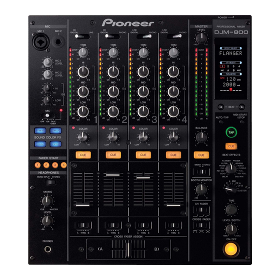
Page 8: Names And Functions Of Parts
NAMES AND FUNCTIONS OF PARTS (OPERATION PANEL) NAMES AND FUNCTIONS OF PARTS OPERATION PANEL MIC 1 MIC 2 MIC 1 LEVEL MIC 2 LEVEL OFF ON TALK OVER HARMONIC SWEEP SOUND COLOR FX CRUSH FILTER FADER START HEADPHONES MONO SPLIT STEREO MIXING MASTER... - Page 9 11. TRIM adjust dial Use to adjust the input level for each channel. (adjustable range: –∞ to +9 dB, mid-position is about 0 dB) 12. Channel equalizer high-range adjust dial (HI) Use to adjust the treble (high-range) frequency sound for each channel.
-
Page 10: Display Section
NAMES AND FUNCTIONS OF PARTS (OPERATION PANEL/DISPLAY SECTION) 30. Headphones level adjust dial (LEVEL) Adjusts the output level of the headphones jack. (adjustable range: –∞ to 0 dB) 31. Headphones jack (PHONES) BPM counter section 32. Beat select buttons (2 BEAT 3) 3 (Beat up): Doubles the calculated BPM. - Page 11 2. Channel select display section The <CH SELECT> indicator lights constantly, and a red frame lights around the number position corresponding to the chosen effect channel selector. 3. Parameter display section <PARAMETER>: The <PARAMETER> indicator lights constantly. AUTO/TAP: [AUTO] lights when the BPM measuring mode is set to AUTO, and [TAP] lights when the BPM measuring mode is set to manual (TAP).
-
Page 12: Mixer Operations
MIXER OPERATIONS (BASIC OPERATIONS) MIXER OPERATIONS BASIC OPERATIONS TRIM HI, MID, LOW 1. Set rear panel POWER switch to ON. 2. Set the input selector switch for the desired channel to choose the connected component. ¶ When using CD input or LINE input, the connection panel’s DIGITAL/CD switch or DIGITAL/LINE switch must be set to [CD] or [LINE]. -
Page 13: Fader Start Function
¶ This setting produces equal curve effects for both sides A and FADER START FUNCTION By connecting the optional Pioneer DJ CD Player control cable, the channel fader and cross fader can be used to start CD playback. When the mixer’s channel fader lever or cross fader lever are moved, the CD player is released from the pause mode and automatically –... -
Page 14: Effect Functions
EFFECT FUNCTIONS (TYPES OF BEAT EFFECTS) EFFECT FUNCTIONS This unit can produce beat effects linked to the BPM, and sound-color effects linked to the COLOR dials provided for each channel, for a total of 18 basic effects (including [SND/RTN]). In addition, by changing the parameters for each kind of effect, an extremely wide range of effect variations can be produced. - Page 15 6. FILTER In units of 1/4, 1/2, 1/1, 2/1, 4/1, 8/1, 16/1, 32/1, or 64/1 beat, the filter frequency is moved, greatly changing the sound coloration. Example 1 cycle = 1/4, 1/2, 1/1, 2/1, 4/1, 8/1, 16/1, 32/1, or 64/1 beat 7.
-
Page 16: Producing Beat Effects
EFFECT FUNCTIONS (PRODUCING BEAT EFFECTS) PRODUCING BEAT EFFECTS Beat effects allow the instant setting of effect times in synch with the BPM (beats per minute), thus allowing the production of a wide variety of effects in synch with the current rhythm, even during live performances. -
Page 17: Type Of Sound-Color Effect
EFFECT FUNCTIONS (TYPE OF SOUND-COLOR EFFECT/USING SOUND-COLOR EFFECTS) TYPE OF SOUND-COLOR EFFECT 1. HARMONIC Detects deviation of the input sound from absolute pitch and automatically compensates to the nearest key. By rotating the dial, the pitch/key can be adjusted within a range of ±6 half-tones. -
Page 18: Effect Parameters
EFFECT FUNCTIONS (EFFECT PARAMETERS) EFFECT PARAMETERS Beat Effect Name Beat Switch Parameter 1 DELAY Sets delay time of 1/8 to 16/1 per 1 beat of BPM time. 2 ECHO (*1) Sets delay time of 1/8 to 16/1 per 1 beat of BPM time. 3 REVERSE DELAY Sets delay time of 1/8 to 16/1 per 1 beat of BPM time. -
Page 19: Midi Settings
A MIDI cable is used to connect components equipped with MIDI connectors to enable the transmission and receipt of data. The DJM-800 uses the MIDI protocol for transmitting and receiving data about component operation and BPM (timing clock). DJ CD Player... -
Page 20: Program Change
SNAPSHOT FILTER FLANGER PHASER Once the DJM-800 is setup with parameters for a given purpose, that REVERB set of parameters can be recorded as a snapshot. When snapshot of ROBOT the current status is recorded, all messages for control change and CHORUS program change are transmitted. -
Page 21: Troubleshooting
Sometimes the trouble may originate from another component. Thus, also check the other electrical appliances also in use. If the trouble cannot be rectified even after checking the following items, contact your dealer or nearest PIONEER service center. Symptom ÷... -
Page 22: Specifications
CONTROL connector Mini phone jacks (Ø3.5 mm) ... 4 4. Accessories Operating Instructions ... 1 Power cord ... 1 Specifications and appearance are subject to change without notice. Published by Pioneer Corporation. Copyright © 2005 Pioneer Corporation. All rights reserved. -
Page 23: Precauciones Para La Manipulación
Enhorabuena por la adquisición de este producto Pioneer. Lea completamente este manual de instrucciones para aprender a operar correctamente el aparato. Después de haber terminado la lectura de las instrucciones, guarde el manual en un lugar seguro para poderlo consultar en el futuro. -
Page 24: Confirmación De Los Accesorios
(Sólo hay compatibilidad con PCM lineal.) 5 Salida MIDI (MIDI OUT) Virtualmente, toda la información de los mandos e interruptores de la DJM-800 pueden emitirse en formato de señal MIDI, permitiendo el control de los componentes exterior a través de MIDI. 6 Otras funciones ¶... -
Page 25: Conexiones
CD para DJ Pioneer. Cuando se han conectado los conectores, puede utilizarse el fundido de la DJM-800 para realizar el inicio/parada del reproductor de CD para DJ. 16. Conectores de salida de monitor de cabina (BOOTH) Conectores de salida de monitor de la cabina del tipo telefónico de... -
Page 26: Conexiones De Las Entradas
Cuando efectúe conexiones digitales, conecte el terminal de salida coaxial digital del reproductor de CD para DJ a uno de los conectores DIGITAL IN de los canales 1 a 4 de la DJM-800; luego, ajuste el interruptor DIGITAL/CD o el interruptor DIGITAL/LINE del canal correspondiente en [DIGITAL], y el selector de entrada en [CD/ DIGITAL] o en [LINE/DIGITAL]. -
Page 27: Conexión De Generadores De Efectos Externos, Conectores De Salida
CONEXIONES (CONEXIÓN DE GENERADORES DE EFECTOS EXTERNOS, CONECTORES DE SALIDA/ACERCA DE LOS CONECTORES MIDI) CONEXIÓN DE GENERADORES DE EFECTOS EXTERNOS, CONECTORES DE SALIDA Salida principal Esta unidad está provista de conectores de salida equilibrada MASTER 1 (compatible con clavijas XLR) y de salida desequilibrada MASTER 2 (compatible con clavijas RCA). -
Page 28: Conexión De Los Micrófonos Y Los Auriculares
CONEXIONES (CONEXIÓN DE LOS MICRÓFONO Y LOS AURICULARES/CONEXIÓN DEL CABLE DE ALIMENTACIÓN) CONEXIÓN DE LOS MICRÓFONOS Y LOS AURICULARES Micrófono La toma MIC 1 de la superficie superior del panel de operación puede utilizarse para conectar un micrófono con clavija telefónica o clavija XLR de 6,3 mm de diámetro. -
Page 29: Nomenclatura Y Funciones De Los Controles
NOMENCLATURA Y FUNCIONES DE LOS CONTROLES (PANEL DE OPERACIÓN) NOMENCLATURA Y FUNCIONES DE LOS CONTROLES PANEL DE OPERACIÓN MIC 1 MIC 2 MIC 1 LEVEL MIC 2 LEVEL OFF ON TALK OVER HARMONIC SWEEP SOUND COLOR FX CRUSH FILTER FADER START HEADPHONES MONO SPLIT STEREO... - Page 30 NOMENCLATURA Y FUNCIONES DE LOS CONTROLES (PANEL DE OPERACIÓN) 11. Control de ajuste del nivel de entrada (TRIM) Se emplea para ajustar el nivel de entrada de cada canal. (Margen ajustable: –∞ a +9 dB, el punto intermedio es aproximadamente 0 dB) 12.
-
Page 31: Sección Del Visualizador
NOMENCLATURA Y FUNCIONES DE LOS CONTROLES (PANEL DE OPERACIÓN/SECCIÓN DEL VISUALIZADOR) 29. Control de mezcla de auriculares (MIXING) Cuando se gira hacia la derecha (hacia [MASTER]), el audio de la salida principal se produce en los auriculares (sólo cuando se ha seleccionado [MASTER] con el botón CUE de los auriculares);... - Page 32 NOMENCLATURA Y FUNCIONES DE LOS CONTROLES (SECCIÓN DEL VISUALIZADOR) 2. Sección de visualización de selección de canales El indicador <CH SELECT> queda constantemente encendido, y se enciende un marco rojo en torno a la posición del número correspondiente al selector de canales del efecto seleccionado. 3.
-
Page 33: Operaciones De La Consola De Mezcla
OPERACIONES DE LA CONSOLA DE MEZCLA OPERACIONES BÁSICAS TRIM HI, MID, LOW 1. Ponga el interruptor POWER del panel posterior en ON. 2. Ajuste el selector de entrada en el canal deseado para seleccionar el componente conectado. ¶ Cuando se emplee la entrada CD o la entrada LINE, el interruptor DIGITAL/CD o el interruptor DIGITAL/LINE del panel de conexiones deberán ajustarse en [CD] o [LINE]. -
Page 34: Función De Inicio Con Fundido
FUNCIÓN DE INICIO CON FUNDIDO Conectando el cable de control del reproductor de CD para DJ Pioneer opcional, podrá emplear el fundido de canales y el fundido cruzado para iniciar la reproducción del disco CD. Cuando se mueva el control deslizante de fundido de canales o el control deslizante de fundido cruzado de la consola de mezcla, se desactivará... -
Page 35: Funciones De Los Efectos
FUNCIONES DE LOS EFECTOS Esta unidad puede producir efectos de compás enlazados con el valor de BPM, y efectos de color del sonido enlazados con los controles COLOR incorporados para cada canal, con un total de 18 efectos básicos (incluyendo [SND/RTN]). Adicionalmente, cambiando los parámetros para cada tipo de efecto, pueden producirse una amplia gama de variaciones de los efectos. - Page 36 FUNCIONES DE LOS EFECTOS (TIPOS DE EFECTOS DE COMPÁS) 6. FILTER La frecuencia del filtro se desplaza, en unidades de compás de 1/4, 1/2, 1/1, 2/1, 4/1, 8/1, 16/1, 32/1, ó 64/1, cambiando en gran medida el colorido del sonido. Ejemplo 1 ciclo = Compás de 1/4, 1/2, 1/1, 2/1, 4/1, 8/1, 16/1, 32/1, ó...
-
Page 37: Producción De Efectos De Compás
PRODUCCIÓN DE EFECTOS DE COMPÁS Los efectos de compás permite el ajuste instantáneo de los tiempos del efecto en sincronización con el valor de BPM (tiempos por minuto), permitiendo de este modo la producción de una amplia variedad de efectos con el ritmo actual, incluso durante interpretaciones en directo. -
Page 38: Tipo De Efecto De Color Del Sonido
FUNCIONES DE LOS EFECTOS (TIPO DE EFECTO DE COLOR DEL SONIDO/EMPLEO DE LOS EFECTOS DE COLOR DEL SONIDO) TIPO DE EFECTO DE COLOR DEL SONIDO 1. HARMONIC Detecta los desvíos del sonido de entrada con respecto al tono absoluto y los compensa automáticamente a la clave más cercana. -
Page 39: Parámetros De Los Efectos
PARÁMETROS DE LOS EFECTOS Efecto de compás Nombre Parámetro del interruptor de compás 1 DELAY Ajusta el tiempo de retardo de 1/8 a 16/1 por 1 tiempo del tiempo de BPM. 2 ECHO (*1) Ajusta el tiempo de retardo de 1/8 a 16/1 por 1 tiempo del tiempo de BPM. -
Page 40: Ajustes De Midi
Para la conexión de componentes provistos de conectores MIDI se emplea un cable MIDI que permite la transmisión y la recepción de datos. El DJM-800 emplea el protocolo MIDI para la transmisión y recepción de datos sobre la operación de componentes y de BPM (reloj de temporización). -
Page 41: Cambio De Programa
REV DELAY TRANS INSTANTÁNEA FILTER FLANGER PHASER Una vez la DJM-800 está configurada con los parámetros para cierto REVERB propósito, este juego de parámetros puede grabarse como una ROBOT instantánea. Cuando se graba la instantánea del estado actual, se CHORUS... -
Page 42: Solución De Problemas
Si el problema no puede solucionarse después de haber verificado los puntos siguientes, póngase en contacto con su distribuidor o con el centro de servicio técnico PIONEER que le quede más cerca. Síntoma No se conecta la alimentación. -
Page 43: Especificaciones
Minitoma telefónica (3,5 mm de diámetro) ... 4 4. Accesorios Manual de instrucciones ... 1 Cable de alimentación ... 1 Especificaciones y aspecto exterior sujetos a cambios sin previo aviso. Publicado por Pioneer Corporation. Copyright © 2005 Pioneer Corporation. Todos los derechos reservados. <DRB1394>... - Page 44 感謝您購買本Pioneer產品。 請詳讀這些操作說明,這樣您才能瞭解如何正操作本產品。完成閱讀操作說明後,請將操作手冊放在安全的位置供將來參考時使用。 在有些國家或地區中,電源插頭和電源開關的形狀有時和說明圖片顯示的不同。但是連接和操作方法相同。 關於處理的注意事項 位置 將本裝置安裝在不會暴露在高溫或潮溼的通風良好位置。 ÷ 不可將本裝置安裝在受到陽光直接照射、靠近火爐或散熱器的 位置。高溫會對機櫃和內部元件造成不良影響。本裝置安裝在 潮溼或多灰塵的環境中也會導致故障或發生意外。 (避免安裝在會使本裝置暴露在油煙、蒸氣或熱氣等靠近烹調器 具的位置。) ÷ 在提袋或 DJ Booth 中使用本裝置時,將它從牆上或其它設備 上拿開以改善散熱的情況。 <DRB1394> 清潔本裝置 ÷ 使用擦拭布擦掉灰塵。 ÷ 表面非常髒時,使用軟布沾上以五倍或六倍的水稀釋的中性清 潔劑後將它擰乾,然後擦拭表面,接著再使用乾布擦拭一次。 不可使用傢俱蠟或清潔劑直接擦拭。 ÷ 不可以在本裝置上或靠近本裝置的位置使用稀釋劑、甲苯、殺 蟲噴劑或其它化學劑,因為這樣會腐蝕本裝置的表面。...
- Page 45 元件連接不會有聲音變差的情況。 數位輸出接頭同樣支援 96 kHz/24 位元和 48 kHz/24 位元的取樣率, 在需要高傳真聲音的情況時使裝置更方便切割音軌。(只有在支援線性 PCM 時。) 5 MIDI 輸出 以 MIDI 訊號格式實際輸出 DJM-800 的所有旋鈕與開關資訊,經由 MIDI 控制外部元件。 6 其他功能 ¶ 可用於連接本裝置與 Pioneer DJ 雷射唱機的控制表,可結合播放與 淡化器的操作 ( 「 切換器開始播放」 )。 ¶ 在每個頻寬內的 +6 dB 到 -26 dB 支援電平控制的內建 「3 波段等化...
-
Page 46: 操作之前 接線
Ø6.3 mm 電話型輸出接頭。 使用於連接外部接頭或類似元件的輸入接頭。 在只有連接 L 頻道時,輸出 L+R 單聲音訊號。 15. 控制接頭 (CONTROL) Ø3.5 mm 迷你接頭,用於連接 Pioneer DJ 雷射唱機的控制接頭。 連接接頭後, DJM-800 的切換器可以用於執行 DJ 雷射唱機上的開始 / 停止功能。 16. BOOTH 監聽器輸出接頭 Ø6.3mm 電話型 Booth 監聽器輸出接頭。 由 Booth 監聽器電平旋鈕(BOOTH MONITOR)個別控制這些接頭的聲音電 平,與主電平旋鈕(MASTER LEVEL)的位置無關。(這些接頭是 TRS 輸出... -
Page 47: 連接輸入接頭
開關或 DIGITAL/LINE 開關至 [DIGITAL],然後設定輸入選擇開關至 [CD/DIGITAL] 或 [LINE/DIGITAL]。 類比轉盤 若要連接類比轉盤,連接轉盤的音頻輸出線至其中一個 2 至 4 PHONO 輸 入接頭。設定相應頻道的輸入選擇開關至 [PHONO]。 DJM-800 的 PHONO 輸入接頭支援 MM 匣。 連接轉盤的接地線至 DJM-800 的其中一個 SIGNAL GND 端子。 ÷ 注意未提供任何 PHONO 輸入接頭給頻道 1 。 DIGITAL/LINE 開關 MASTER 2 PHONO POWER... -
Page 48: 連接外接效果器、輸出接頭
接線(連接外接效果器、輸出接頭 / 關於 MIDI 接頭) 連接外接效果器、輸出接頭 主音輸出接頭 本裝置有平衡輸出 MASTER 1 接頭 (支援 XLR 插頭) 和未平衡輸出 MASTER 2 接頭 (支援 RCA 插頭)。 使用 MASTER ATT 開關調整輸出電平以符合所使用電源放大器的輸入靈 敏度。 如果操作面板的 STEREO/MONO 開關設定為 [MONO],主音輸出將是結合 L+R 頻道單音的聲音。 Booth 監聽器輸出接頭 這是一個 TRS 輸出,支援Ø6.3 mm 音響的插頭。此輸出的音量由 BOOTH MONITOR 電平旋鈕控制,不屬於主音輸出電平設定值。... -
Page 49: 連接麥克風和耳機
連接麥克風和耳機 麥克風 操作面板上側表面的 MIC 1 插孔可使用於連接附有 Ø6.3 mm 音響插頭 或 XLR 插頭的麥克風。 操作面板上側表面的 MIC 2 插孔可使用於連接附有 Ø6.3 mm 音響插頭 的麥克風。 ¶ 連接面板上的 MIC SIGNAL 開關設定至 [CUT] 時,不會輸出任何來 自 BOOTH 監聽器輸出接頭的麥克風聲音。 麥克風 1 (麥克風 1) 麥克風 2 連接電源線 請在最後才連接電源線。 ÷ 完成所有其它接線後,將隨附的電源線連接至播放器背面的 AC 插孔,然後連接插頭至標準式牆上電源插座或放大器的輔助電源插座。 ÷... -
Page 50: 各個零件的名稱和功能
各個零件的名稱和功能(操作面板) 各個零件的名稱和功能 操作面板 MIC 1 MIC 2 MIC 1 LEVEL MIC 2 LEVEL OFF ON TALK OVER HARMONIC SWEEP SOUND COLOR FX CRUSH FILTER FADER START HEADPHONES MONO SPLIT STEREO MIXING MASTER LEVEL PHONES 麥克風輸入控制部份 1. 麥克風 1 輸入插孔 (MIC 1) 使用於連接附有... - Page 51 11. 修飾調整旋鈕 (TRIM) 使用於調整每個頻道的輸入電平 (可調整範圍:-∞ 至 +9 dB, 中間位置約 0 dB) 12. 頻道等化器高範圍調整旋鈕 (HI) 使用於調整每個頻道的高 ( 高範圍) 圍:-26 dB 至 +6 dB) 13. 頻道等化器中範圍調整旋鈕 (MID) 使用於調整每個頻道的中範圍頻率聲音。(可調整範圍:-26 dB 至 +6 dB) 14. 頻道等化器低範圍調整旋鈕 (LOW) 使用於調整每個頻道的低 ( 低範圍) 圍:-26 dB 至 +6 dB) 15.
-
Page 52: 顯示部份
各個零件的名稱和功能(操作面板 / 顯示部份) 30. 耳機電平調整旋鈕 (LEVEL) 調整耳機插孔的輸出電平。(可調整範圍:- ∞ 至 0 dB) 31. 耳機插孔 (PHONES) BPM 計數器部份 32. 拍子選擇按鍵 (2 BEAT 3) 3 (拍子增加): 加倍所計算的 BPM 。 2 (拍子減少): 將所計算的拍子減半。 (58 頁) ¶ 有些效果可設定在“3/4”。 33. MIDI 開始 / 停止按鍵 (MIDI START/STOP) 使用於切換開始與結束... - Page 53 2. 頻道選擇顯示部份 〈CH SELECT〉 指示燈穩定亮起,而且相應所選擇效果聲道選擇器 的數字位置周圍的紅色框亮起。 3. 參數顯示部份 〈PARAMETER〉: 〈PARAMETER〉指示燈穩定亮起。 AUTO/TAP: BPM 測量模式設定為 AUTO 時,[AUTO] 亮起。 BPM 測量模式設 定為手動 (TAP) 時,[TAP] 亮起。 BPM 計數器顯示 (3 位數): 在 AUTO 模式中,顯示自動偵測的 BPM 值。不能自動偵測到 BPM 的計數時,顯示器閃亮以前偵測的數值。在手動 (TAP) 模式中, 顯示 TAP 輸入指定的 BPM 值。 BPM: 穩定亮起。...
-
Page 54: 混音器操作
混音器操作(基本操作) 混音器操作 基本操作 TRIM HI, MID, LOW 1. 將後面板電源 POWER 設定在 ON 位置。 2. 設定想要的聲道之輸入選擇開關以選擇連接的元件。 ¶ 使用 CD 輸入或 LINE 輸入時,接線面板的 DIGITAL/CD 開關或 DIGITAL/LINE 開關必須設定至 [CD] 或 [LINE]。 ¶ 使用 DIGITAL 輸入時,連線面板的 DIGITAL/CD 開關或 DIGITAL/ LINE 開關必須設定至 [DIGITAL]。 3. 使用 TRIM 旋鈕調整輸入電平。 4. -
Page 55: 切換器開始功能
切換器開始功能 透過連接選購的 Pioneer DJ 雷射唱機控制連接線,可使用聲道切換器 和交替淡化器開始播放 CD 。 移動混音器的聲道切換器桿或交替淡化器桿後,雷射唱機離開暫停模式, 而且自動立劇開始播放所選擇的音軌。另外在切換器桿回到原始位置後, 雷射唱機回到它的提示點 (往後提示),因此成為「取樣器」式播放。 交替淡化器播放和往後提示播放 指定至交替淡化器聲道 A 的雷射唱機設定在提示點待機時,將交替淡化 器桿從右側 (B 側) 移動至左側 (A 側) 會自動啟動聲道 A 的雷射唱機 上的播放。 交替淡化器桿達到左 (A) 側時,指定至聲道 B 的雷射唱機進入向後提 示 (返回提示點)。此外,指定至交替淡化器聲道 B 的雷射唱機設定在 提示點待機時,將交替淡化器桿從左側 (A 側) 移動至右側 (B 側) 會... -
Page 56: 效果功能
效果功能(拍子效果的類型) 效果功能 本機可針對每一聲道利用 BPM 產生相關的最佳效果,以及利用 COLOR 旋 鈕產生相關的音色效果,共計有18種基本效果(包含[SND/RTN])。此外, 變更每種效果的參數可產生極大範圍的效果變化。 經由 TIME 旋鈕 (參數 1) 變更暫時參數和經由 LEVEL/DEPTH 旋鈕 (參 數 2) 變更數量成數可達成多種不同的拍子效果。 藉由改變 COLOR 旋鈕的位置即可增加音色的效果。而藉由結合節拍效果 與音色效果,更可產生範圍更廣的演奏效果。 拍子效果的類型 1. DELAY (一個重複聲) 此功能可以快速和簡易地加入 1/8 、 1/4 、 1/2 、 3/4 、 1/1 、 2/1 、... - Page 57 6. FILTER 以 1/4 、 1/2 、 1/1 、 2/1 、 4/1 、 8/1 、 16/1 、 32/1 或 64/1 拍的單位移動過濾器頻率可大幅變更聲音著色。 範例 1 個周期 = 1/4 、 1/2 、 1/1 、 2/1 、 4/1 、 8/1 、 16/1 、 32/1 或 64/1 拍 7.
-
Page 58: 製造拍子效果
效果功能(製造拍子效果) 製造拍子效果 拍子效果可立即設定與 BPM (每分鐘拍子數) 同步旳效果次數,即使在 現場演奏時都可產生與目前節奏同步的多種效果。 1. 按下 AUTO/TAP 按鍵設定每分鐘拍子數 (BPM= 音軌速度) 測 量模式。 AUTO: 自動偵測輸入音樂訊號的 BPM 。 TAP: 觸點 TAP 按鍵以手動輸入 BPM 。 ¶ 每次先開啟電源時,功能預設為 [AUTO] 模式。 ¶ 所選擇模式 [AUTO/TAP] 的指示燈在顯示幕中亮起。 ¶ 如果無法自動偵測到音軌的 BPM,顯示的 BPM 計數器將會閃爍。 ¶ AUTO 模式的有效範圍是 70 至 180 BPM 。 它可能無法精確測量某些音軌。... -
Page 59: 音色效果的類型
音色效果的類型 1. HARMONIC 感應輸入音效有別於絕對音高(absolute pitch)的差異並自動補償 至最為相近的音調。藉由旋鈕的轉動,即可將音高 / 音調調整在 ± 6 半音的範圍內。 COLOR 輸入音效 補償音效 2.SWEEP 此功能轉換過濾器的頻率,使音調產生大變化。往順時針方向旋轉 旋鈕時產生帶通過濾器的效果,往逆時針方向旋轉旋鈕時產生陷口 過濾器的效果。 陷口過濾器 COLOR 1 kHz 頻率 3.CRUSH 此效果輕微「碎裂」聲音,套用特定重音至聲音。 4. FILTER 已偏移過濾器頻率,造成音調的大幅變化。 向右旋轉旋鈕產生高通過濾效果,向左旋轉旋鈕產生低通過濾效 果。 低通過濾 高通過濾 COLOR 頻率 運用音色效果 HARMONIC, SWEEP, FILTER, CRUSH 音色效果主要是利用每一聲道的 COLOR 效果參數旋鈕所產生的。 * 音色效果不適用於麥克風輸入。... -
Page 60: 效果參數
效果功能(效果參數) 效果參數 拍子效果 名稱 拍子切換參數 1 DELAY 設定 BPM 時間每 1 拍的 1/8 至 16/1 延遲時間。 2 ECHO (*1) 設定 BPM 時間每 1 拍的 1/8 至 16/1 延遲時間。 3 REVERSE DELAY 設定 BPM 時間每 1 拍的 1/8 至 16/1 延遲時間。 4 PAN 設定分配至左... -
Page 61: Midi 的設置
COLOR FADER CF ASSIGN 同步化音頻訊號至外接音源器,或使用 DJM-800 資訊操作外接音源器 1. 使用市售的 MIDI 連接線連接 DJM-800 的 MIDI OUT 接頭至 MIDI 音源器的 MIDI IN 接頭。 ¶ 設定 MIDI 音源器的同步模式為「從屬」。 ¶ 無法同步化不支援 MIDI 時脈的 MIDI 音源器。 ¶ 無法穩定偵測和測量音軌的 BPM 可能無法達成同步化。 ¶ 可使用以 TAP 模式設定的 BPM 值輸出時脈。... -
Page 62: 變更編程
1 1 1 DELAY 1 ECHO - REV DELAY PAN TRANS 快照 FILTER FLANGER PHASER 因特定用途而使用參數設定 DJM-800 後,可記錄該參數的設定作為快 REVERB 照。記錄目前狀態的快照後,傳送所有變更控制和變更編程的訊息。按住 ROBOT MIDI START/STOP 鍵傳送快照。 CHORUS ROLL REV ROLL SND/RTN 註解 0 至 127 0 至 127 0 至 127 0 至 127 0 至... -
Page 63: 故障排除
故障排除 錯誤的操作常造成問題和故障。如果您認為本機發生故障,請先檢查下列重點項目。有時候故障可能是其它元件所造成。另外也要檢 查使用中的電氣設備。 如果在檢查下列項目後無法排除故障,請洽詢您的經銷商或最近的 PIONEER 服務中心。 徵狀 ÷ 未連接電源線。 無電源 ÷ 未正確設定輸入選擇鈕。 沒有聲音或音量太低。 ÷ 未正確設定後面板的 DIGITAL/CD 輸入選擇 ÷ 未正確連接線路或線路鬆脫。 ÷ 插孔或插頭髒污。 ÷ 將後面板主音輸出衰減器開關 (MASTER ATT) ÷ 將後面板的 MIC SIGNAL 開關設定至 BOOTH 輸出中未產生麥克風聲音。 ÷ 數位輸出取樣率 (fs) 不符合所連接元件的 無數位輸出。 ÷ 主音輸出電平太高。 聲音失真。... - Page 64 規格 規格 1. 一般 電源 ... AC 110 V ∼ 240 V, 50 Hz/60 Hz 耗電 ... 30 W 操作溫度 ... +5 ℃到 +35 ℃ 操作溼度 ... 5 % 到 85 % (無凝結) 重量 ... 7.5 kg 最大尺寸 ... 320 (寬) × 381 (深) × 108 (高) mm 2.
- Page 65 <DRB1394>...
- Page 66 <DRB1394>...
- Page 67 <DRB1394>...
-
Page 68: Block Diagram
Return In Master Master PIONEER CORPORATION 4-1, Meguro 1-Chome, Meguro-ku, Tokyo 153-8654, Japan PIONEER ELECTRONICS AUSTRALIA PTY. LTD. PIONEER ELECTRONICS ASIACENTRE PTE. LTD. PIONEER ELECTRONICS DE MEXICO S.A. DE C.V. <05L00000> MIC 1 PHONES MIC 2 MASTER CH 1 -COM...