
Related Manuals for GFA ELEKTROMAT SE 7.32 WS-25,40


Summary of Contents for GFA ELEKTROMAT SE 7.32 WS-25,40
-
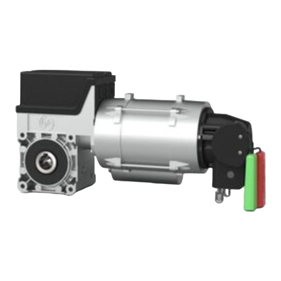
Page 1: Installation Instructions
Installation Instructions ELEKTROMAT SE 7.32 WS-25,40 RP07/32WRD Model: 10002245 10006 -en- Status: 05.07.2016... - Page 2 GfA ELEKTROMATEN UK Ltd Titan Business Centre Spartan Close Warwick CV34 6RR United Kingdom sales@gfa-elektromaten.co.uk www.gfa-elektromaten.co.uk...
-
Page 3: Table Of Contents
Table of contents General safety information ....................4 Technical Data ........................ 5 Mechanical installation ....................6 Electrical installation ..................... 10 Limit switch adjustment ....................11 Motor connection ......................12 ... -
Page 4: General Safety Information
1 General safety information Specified normal use The drive unit is intended for sectional doors with full counter-balancing. The safe operation is only guaranteed with normal specified use. The drive unit is to be protected from rain, moisture and aggressive ambient conditions. No liability for damage caused by other applications or non-observance of the information in the manual. -
Page 5: Technical Data
2 Technical Data Type SG 50 Output torque Output speed Output shaft / hollow shaft 25,40 Maximum holding torque Maximum door weight 4000 Supply voltage 1N~ 230 Operating current 3,90 Operating frequency Power factor cos φ 0,99 Maximum movement per hour Class of protection IP 65 Limit switch range... -
Page 6: Mechanical Installation
3 Mechanical installation Prerequisites The permissible loads on walls, fastenings, mountings and transmission elements must not be exceeded, even for maximum holding torques or locking torques (▶ refer to technical data). Connection elements: ▶ Self-locking connection ▶ Utilize the hole diameter ▶... - Page 7 Mounting Eight threads are provided for mounting. ▶ Use at least 2 of these (①). Keys are used to connect to the door shaft. ▶ Use a key that is at least as long as the hollow shaft (②). BAGAD0 1 0 0 1 _Z0 0 2 8 x (M8x16)
- Page 8 Installation The descriptions below apply to general door specifications. The specifications of the door manufacturer must also be observed during installation. Warning - Potential injury or danger to life! During installation, be sure to use a lifting device that has a sufficient load-carrying capacity.
- Page 9 ▶ Attach the drive unit. BAGAE0 1 0 0 3 _Z0 0 3 ▶ Tighten all connection elements (M8) to 25 BAGAE0 1 0 0 6 _Z0 0 2 Nm. Install all other connection elements according to the specifications of the door manufacturer.
-
Page 10: Electrical Installation
4 Electrical installation Warning - Danger to life from electric current! Switch the mains OFF and check that the cables are de-energised Observe the applicable regulations and standards Make a proper electrical connection Use suitable tools Performing electrical installation Remove the cover. -
Page 11: Limit Switch Adjustment
5 Limit switch adjustment The adjustment of the final limit positions OPEN and CLOSE is described in the instructions for the door control panel. -
Page 12: Motor Connection
6 Motor connection Capacitor Motor X13 Motor plug 7 Limit switch connection Thermal contact S10 Manual operation X12 DES connection Safety circuit Channel B (RS485) Ground Channel A (RS485) Safety circuit Supply network... -
Page 13: Emergency Manual Operation Sk (Rapid Hand Chain Operator)
8 Emergency manual operation SK (rapid hand chain operator) The emergency manual operation is provided as a means of opening or closing doors that do not have electric power supply. Operation interrupts the control voltage. Electrical operation is no longer possible. Warning - Injury through improper operation! ... -
Page 14: Completing Commissioning / Inspection
9 Completing commissioning / inspection Check the following components and then install all covers. Gearbox Check the drive unit for loss of oil (a few drops can be neglected). Protect the output-shaft permanently against corrosion. Mounting Check that all connection elements (consoles, torque mounts, screws, locking rings, etc.) are secure and in proper condition. -
Page 15: Declaration Of Incorporation / Conformance
Declaration of conformity in terms of EMC Directive 2014/30/EU We, the GfA ELEKTROMATEN GmbH & Co. KG hereby declare that the following products are conform with the above EC Guideline and are only intended for installation in door equipment. SE 7.32 WS-25,40...
Need help?
Do you have a question about the ELEKTROMAT SE 7.32 WS-25,40 and is the answer not in the manual?
Questions and answers