Advertisement
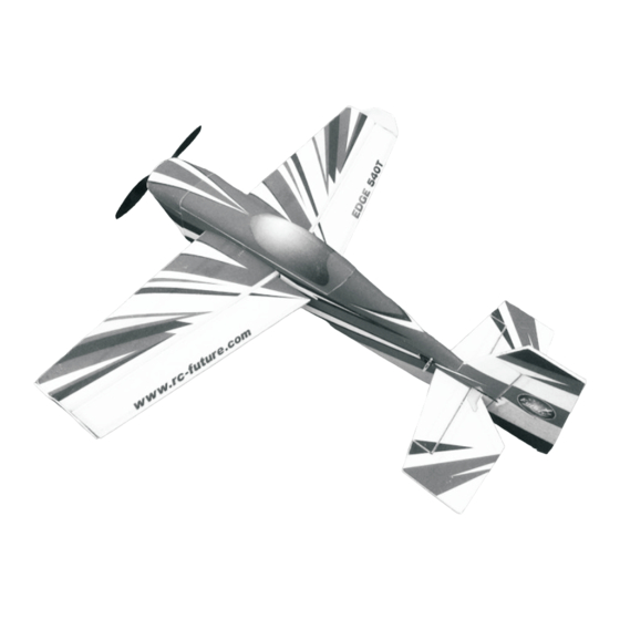
Electric radio-controlled model aircraft
Electric radio-controlled model aircraft
Electric radio-controlled model aircraft
Caution: Please read the manual carefully before installation.
Caution: Please read the manual carefully before installation.
Caution: Please read the manual carefully before installation.
This product is not a toy. Please seek assistance from people
This product is not a toy. Please seek assistance from people
This product is not a toy. Please seek assistance from people
with RC model experience for the assembly and fl fl ying.
with RC model experience for the assembly and fl fl ying.
with RC model experience for the assembly and fl fl ying.
Installation Instructions
Installation Instructions
Installation Instructions
Future Models
Future Models
Future Models
Advertisement
Table of Contents

Related Manuals for Future EDGE540

Summary of Contents for Future EDGE540
- Page 1 Electric radio-controlled model aircraft Electric radio-controlled model aircraft Installation Instructions Installation Instructions Installation Instructions Future Models Future Models Future Models Caution: Please read the manual carefully before installation. Caution: Please read the manual carefully before installation. Caution: Please read the manual carefully before installation.
- Page 2 Please open the package and check that it contains all required parts. If any parts are missing, please contact the dealer. Product Specifi fi cations: Wingspan: 965mm Length: 980mm Wing area: 20.4 dm2 Total weight: about 630 g (including a 3s1000 mAh 25c battery) Center of gravity position: 95mm from the wing leading edge Reference Power Confi...
- Page 3 1. Connect servo extension leads to the 2. Install the elevator and rudder servos into the airframe. elevator and rudder servo cables. 4. Locate the landing gear and landing 3. Feed the elevator and rudder servo gear plate. cables through the inside of the fuselage. 5.
- Page 4 8. Carefully insert the horizontal stabiliser into 7. Carefully insert the elevator into the the fuselage. Insert the elevator hinges into fuselage, noting that the elevator needs to be the horizontal stabiliser. Measure to ensure upside down and back-to-front when inserted. that the horizontal stabiliser is evenly spaced Once it is fully inserted, you can fl...
- Page 5 13. Use a small amount of thin CA glue to 14. Use a suitable foam glue to reinforce the horizontal stabiliser to fuselage join on both attach the horizontal stabiliser to the fuselage. Note: Do not use too much thin CA glue, as it sides top and bottom.
- Page 6 19. Insert the rudder hinges into the tail, 20. Ensure that there is a rudder hinge gap of leaving a hinge gap of about 1mm. Adjust about 1mm to allow it to move freely. Use thin the height of the rudder so that the tail wheel CA glue to attach the rudder hinges to the horizontal stabiliser hinge slots.
- Page 7 25. Install the motor using 4 wood screws. 26. Install the electronic speed Ensure the motor rotates smoothly. controller (ESC). Connect the motor to the speed controller. 27. Install the EZ connectors on to your 28. Cut 8 pieces of heat shrink tubing of servo arms.
- Page 8 31. Confi fi gure each aileron as shown. With the 32. Confi fi gure the rudder as shown. control surface in the neutral position and the servo arm at 90 degrees to the pushrod, tighten the EZ Connector grub screw to lock the pushrod in place.
- Page 9 fl fl y this aircraft. control surfaces are in the correct neutral We hope that you enjoy this product. position and move in the correct direction. Future Models Ltd. Skype:futuremodel E-mail:futuremodel@qq.com QQ:401587791 Http://www.rc-future.com...
Need help?
Do you have a question about the EDGE540 and is the answer not in the manual?
Questions and answers