Subscribe to Our Youtube Channel
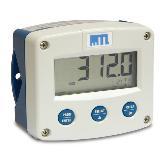
Summary of Contents for Eaton MTL661
- Page 1 DRAFT - 20 November 2014 Instruction manual September 2016 MTL intrinsic safety solutions INM 660 rev 14 MTL661/2/3/5 IS, Loop-Powered Indicators...
-
Page 2: Declaration Of Conformity
DRAFT - 20 November 2014 DECLARATION OF CONFORMITY A printed version of the Declaration of Conformity has been provided separately within the original shipment of goods. However, you can find a copy of the latest version at http://www.mtl-inst.com/certificates INM 660 rev 14... -
Page 3: Table Of Contents
DRAFT - 20 November 2014 CONTENTS DECLARATION OF CONFORMITY . . . . . . . . . . . . . . . . . . . . . . . . . . . . . . . . . . . . . . . . . . . . . . . . . . . . . . . . . . . . . . II ABOUT THIS MANUAL . -
Page 4: Safety Instructions
Check all connections, settings and technical specifications of ◆ requirements relating to the safety of their installations, and the various peripheral devices with the MTL661/2/3/5 supplied. these requirements should also be met". For further ATEX information on this component see Section 6. -
Page 5: About This Manual
ENTER please read chapter 3. available. For additional information, please contact your supplier. A hazardous situation may occur if the MTL661/2/3/5 is not used for its This key is used to SELECT current and 0% / 100% SELECT designed purpose, or if it is used incorrectly. Please take care to note value. -
Page 6: Configuration
“SETUP” at the bottom of the display. The number is a exit SETUP automatically. combination of two figures. The first figure indicates the function- SETUP can be reached at all times while the MTL661/2/3/5 group and the second figure the sub-function. Additionally, each remains fully operational. - Page 7 000000 - 11111.1 - 2222.22 - 333.333 seconds. If no keys are pressed for 2 minutes, the NOTE MTL661/2/3/5 will leave the SETUP mode automatically. 14 OFFSET The offset is the minimum displayed value of the range of 3 .1 .2 Setup functions and variables measurement.
- Page 8 21 SIGNAL that moment, the analogue input value must be more than the The MTL661/2/3/5 can process the 4-20mA signal in two ways: calibrated value before the signal will be processed. DEFAULT – This resets the calibration to the manufacturer’s factory 1) Interpolation: the signal is processed linearly setting.
-
Page 9: Installation
See also manufacturer’s plate). Even an IP67 (NEMA 4X) casing should Section 4.5 for details of wall and pipe mounting the MTL661(B). NEVER be exposed to strongly varying (weather) conditions. -
Page 10: Accessories For Mounting Displays
Figure 11 - Grounding aluminium enclosure. Figure 12 Wall mounting plate The wall mounting plate is for use with any of the MTL661 or MTL663 display models. Holes are provided in the plate to accommodate bolts or screws up to 5mm diameter and the rear of the display has relief for the heads of the bolts/screws. - Page 11 4 .5 .2 Using the PMA66 pipe mounting adaptor The PMA66 pipe mounting adaptor, shown in Figure 13, has a stainless steel bracket, to enable an MTL661 or MTL663 field display to be mounted on any vertical pipe that has an outside PIPE MOUNTING FACE diameter between 50 and 80mm.
-
Page 12: Maintenance
MTL661/2/3/5 in such a way that no condensation MTL66x(B)-NA Zone 2 will occur, for example by placing a sachet of dry silica-gel crystals in When several apparatus are installed in the same panel or the casing just before closing it. -
Page 13: Product Labelling
DRAFT - 20 November 2014 PRODUCT LABELLING Example of top label for models MTL661(B), MTL662(B) and MTL663(B) Example of rear label for models MTL661(B), MTL662(B) and MTL663(B) Example of rear label for model MTL665(B) Example of inside label for model MTL66x(B)-NA... -
Page 14: Case Details
Aluminium 300g Case style 'A' front view side view rear view bottom view 25mm (0.98”) MTL661 - Threaded M20 MTL663 - Drilled Æ 20 (0.79”) 130 (5.12”) 75 (2.95”) 112 (4.41”) Case style 'B' front view side view panel cutout 14 (0.55”) -
Page 15: Csa Control Drawing
DRAFT - 20 November 2014 CSA CONTROL DRAWING INM 660 rev 14... - Page 16 MTL Instruments GmbH, Heinrich-Hertz-Str. 12, 50170 Kerpen, Germany UNITED ARAB EMIRATES Cooper Industries/Eaton Corporation Tel: +49 (0)22 73 98 12 - 0 Fax: +49 (0)22 73 98 12 - 2 00 Office 205/206, 2nd Floor SJ Towers, off. Old Airport Road, E-mail: csckerpen@eaton.com...


Need help?
Do you have a question about the MTL661 and is the answer not in the manual?
Questions and answers