Advertisement
Quick Links
WARNING
•
To avoid fire, shock, or death, turn off power at circuit breaker and test that power is off
before wiring.
•
Read instructions completely before installation and retain for future reference.
•
Observe all national and local electrical and safety codes.
•
Disconnect power when servicing or changing loads.
•
Alterations or modifications to the device will void the warranty.
•
For outdoor locations, rain-tight or wet location conduit hubs that comply with the re-
quirements of UL 514B Conduit, Tubing, and Cable Fittings, must be used.
ELECTRICAL RATINGS
N.O. Contacts:
40A Resistive @ 120~277VAC
1HP, 16FLA, 90LRA @ 120VAC
2HP, 12FLA, 52LRA @ 208~277VAC
30A Ballast @ 120VAC
20A Ballast @ 277VAC
15A Tungsten @ 120VAC
300VA Pilot Duty 120~240VAC
N.C. Contacts:
30A Resistive @ 120~277VAC
1HP, 12FLA, 30LRA @ 120VAC
2HP, 10FLA, 30LRA @ 240VAC
2A Tungsten @ 120VAC
10A Ballast @ 277VAC
WIRING CONNECTIONS:
Screw box lug terminals
ENVIRONMENTAL RATINGS:
Operating Temperature Range:
–40°F to 131°F (–40°C to 55°C)
Operating Humidity:
10 - 95% RH, non-condensing
ENCLOSURE DIMENSIONS:
8.795" x 6.631" x 2.935"
(H x W x D)
SHIPPING WEIGHT:
2 lbs.
AGENCY APPROVALS:
UL Listed
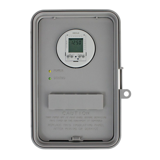
GM40AVE Series General Purpose
Electronic Commercial Time Switches
INSTALLATION INSTRUCTIONS
1.
To avoid fire, shock, or death, turn off power at the circuit breaker and test that
power is off before wiring.
2.
Open door and remove the interior protective cover by releasing the spring
latch (see figure 1 below).
3.
Remove the printed circuit board by releasing the spring latch holding the bot-
tom of the board (see figure 2 below).
4.
Select knockouts to be used. Remove the inner 1/2" knockout by inserting a
flathead screwdriver in the slot and carefully punch the knockout loose. Re-
move slug. If 3/4" knockout is required, remove the outer ring with pliers after
removing the 1/2" knockout. Smooth edge with knife, if necessary.
5.
Place the enclosure in the desired mounting location, and mark the three
mounting holes (refer to Figure 3 below for dimensions). Install the top screw
first with one of the supplied spacers, and then hang the enclosure by the key-
hole. Drive the remaining two screws at the bottom of the enclosure through
the mounting holes while passing each screw through one of the supplied
spacers and in to the wall.
6.
Connect conduit hubs to conduit before connecting the hubs to the enclosure.
After inserting hubs into enclosure, carefully tighten hub lock nut. Do not over-
torque.
7.
Replace printed circuit board making sure to engage spring latch at the bot-
tom of PCB.
8.
Wire in accordance with national and local electrical and safety codes (see
wiring diagrams on page 3).
9.
Grounding: Terminate all ground wires to the ground lug inside the case at the
bottom of the enclosure.
10.
Replace interior protective cover.
Interior Protective Cover
Figure 1 - Spring Latch
PROGRAMMING INSTRUCTIONS
The installer should refer to the supplemental instruction manual included with
this unit for information regarding setting the time, symbols, keys and program-
ming.
AC voltage must be present at terminals L1 and L2/N for the relays to operate
and the status indicator to change from 1
Timer Mechanism
Figure 2 - PCB Latch
Interior Protective Cover Removed
to 1
2-1/2"
Figure 3 - Rear View of Enclosure
with mounting hole dimensions
.
6-1/8"
Advertisement

Related Manuals for Grasslin GM40AVE Series


Summary of Contents for Grasslin GM40AVE Series
-
Page 1: Installation Instructions
GM40AVE Series General Purpose Electronic Commercial Time Switches WARNING • To avoid fire, shock, or death, turn off power at circuit breaker and test that power is off before wiring. • Read instructions completely before installation and retain for future reference. - Page 2 APPLICATION The GM40AVE Series Time Controls are universal, electronic time switches designed for general purpose commercial appli- cations. The control operates on any AC voltage from 120VAC to 277VAC. The mechanism is mounted in an indoor/outdoor enclosure and has been designed for the control of lighting,...
- Page 3 A fuse or circuit breaker shall be connected in series with each ungrounded conductor (and shall be able to simultaneously open each conductor). • Jumper wires are not included. GM40AVE SERIES TYPICAL WIRING DIAGRAMS 120 VAC One Load 120 VAC Two Loads TIMER TIMER...
- Page 4 GM40AVE SERIES TROUBLESHOOTING GUIDE WARNING • Some terminals in the Time Switch may be energized even if the yellow and green LED indicators are OFF. • Check all terminals and wires with an appropriate voltage checker before touching. PROBLEM: LOAD (Lights/Pumps/Motors, etc) will NOT turn ON or OFF Verify that all wiring connections are correct.
Need help?
Do you have a question about the GM40AVE Series and is the answer not in the manual?
Questions and answers