Table of Contents
Advertisement
Advertisement
Table of Contents

Related Manuals for Nastec VASCO


Summary of Contents for Nastec VASCO
- Page 1 Operating manual VASCO manVASCO_eng_05.docx...
-
Page 2: Table Of Contents
4.2 Electromagnetic compliance ..............................9 4.3 Installation with long motor cables ............................9 5. VASCO installation ................................10 5. VASCO Installation for constant pressure control ........................12 5.1.1 Pressure tank ................................12 5.1.2 Pressure sensor ................................12 6. VASCO Use and Programming ............................13 6.1 VASCO display .................................. -
Page 3: Vasco Introduction
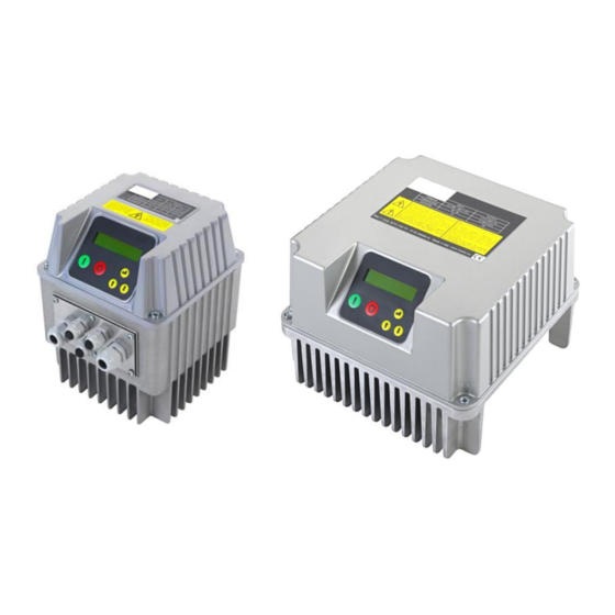
1. VASCO Introduction VASCO is a variable frequency drive designed to control and protect pumping systems by varying the output frequency to the pump. VASCO can be applied to both new and existing pumping systems, and provides: energy and cost savings ... -
Page 4: Technical Characteristics
PWM configurable: 2.5 ,4, 6, 8, 10 kHz * auxiliary cooling fan of the VASCO, used in wall mounted applications, has a protection rating of IP20. If you require the version with IP55, please contact the supplier. VASCO is able to power the motor with a higher current for a short period of time according to the linear relation: 101% of the nominal current for 10min., 110% nominal current for 1 min. -
Page 5: Electric Wiring
4. Electric wiring Power board VASCO 209,214 Power supply: Output: 230 V AC auxiliary fans (wall LINE: L1, L2, earth 3 ph motor: mounting kit) It is recommended to use cable earth ,U,V,W, FAN: F1, F2 lugs 1 ph motor: earth, U (running), V (common) It is recommended to use cable lugs. - Page 6 Power board VASCO 406,409 Power supply: Motor output: 12 V dc auxiliary fan (wall mounting kit) : LINE: GND , L1, L2, L3, MOTOR: U, V, W, GND 0VE, + VE It is recommended to use cable It is recommended to use cable WARNING: respect the polarity.
- Page 7 Power board VASCO 414,418,425,430 Power supply: Motor output: 12 V dc auxiliary fans (wall mounting kit) LINE: L1, L2, L3, GND MOTOR: U, V, W, GND VENT: +, - It is recommended to use cable It is recommended to use cable WARNING: respect the polarity.
- Page 8 Control board Analog inputs (10 or 15 Vdc): Digital outputs: RS485: 1. AN1: 4-20 mA: pressure sensor motor run signal: S+ 2. AN2: 4-20 mA: auxiliary S- NO1, COM1: closed contact with motor pressure sensor G running.
-
Page 9: Protections
For motor cable lengths up to 50 meters it’s recommended For motor cable lengths greater than 50 meters it’s to place between VASCO and motor a dv / dt reactance, recommended to place between VASCO and motor a available on request. -
Page 10: Vasco Installation
VASCO can be installed directly on the fan cover of the motor or mounted on the wall. Motor mounting kit In this application VASCO is cooled by the motor fan. Motor kit (available upon request) allows a solid coupling of the two units and it is composed of:... - Page 11 Make sure to properly attach the grid of the auxiliary cooling fan. Make sure to remove the auxiliary cooling fan if VASCO is coupled to a motor. Failure to do so creates a high risk of overheating the motor and VASCO unit.
-
Page 12: Vasco Installation For Constant Pressure Control
5.1.2 Pressure sensor VASCO requires a pressure sensor with a linear output signal within the range 4 – 20 mA. The pressure transducer can be powered by any range of DC Voltage which includes the value 15 V dc. It is necessary to set the pressure sensor characteristics in the initial configuration menu or in the installer menu (please check the relevant chapter on setting parameters). -
Page 13: Vasco Use And Programming
Screen is a back-lit LCD displaying 2 rows of 16 digits each. Alarms are indicated by an audible signal. 6.2 Initial configuration When VASCO is switched on for the first time, the initial setting menu is displayed for the initial setting of parameters to configure pump characteristics, pressure sensor range, and system characteristics. - Page 14 The pressure value to be kept constant. Set pressure p = XX.X [bar] If ON is selected, after a lack of voltage, VASCO returns to its normal Autorestart status; if VASCO was powering the pump before the voltage drop, it resumes powering the pump automatically.
-
Page 15: Initial View
6.3 Initial view When first powering the VASCO, the display shows : release of display software (LCD = X.XX) and the release of inverter software (INV = X.XX) as shown below: LCD = X.XX INV = X.XX The following End User messages are displayed by pushing the scroll buttons:... -
Page 16: Menu View
Constant pressure: VASCO changes the speed of pump to keep the pressure constant, independent of water demand Control mode Fixed frequency: VASCO feeds the pump a set frequency, so the speed of motor is kept constant. Constant press. - Page 17 Dry run cosphi the pump manufacturer or test by closing the 0.65 suction and checking the value on the VASCO cosphi = X.XX display; a value can be set by assuming a dry cosphi equivalent to 60% of the rated cosphi...
- Page 18 parameter desciption The pressure value to be kept constant. Set pressure p = XX.X [bar] Pressure compensation at the maximum p loss compens. frequency for each pump. Acting on the green button you can reverse the sign. p = XX.X [bar] The pressure value to be kept constant.
- Page 19 Ramp Q=0 If, during this time, the p checked goes below the (p_set -delta start pres), VASCO powers the t = XX [s] motor again; otherwise, VASCO will stop the pump following the min freq. of motor ramp.
- Page 20 Function to enable multiple VASCO’s to work in parallel as described in the technical appendix COMBO (see the relevant chapter). Up to 8 VASCO units can be connected in parallel. ON/OFF VASCO’s communication through RS 485 gates is granted by a private protocol.
-
Page 21: Advanced Parameters
---> software without physically changing wires at the ---> / <--- terminals. By selecting N.A. (normally open) VASCO runs the motor if the digital input 1 is open; motor will Digital input 1 be stopped if the digital input 1 is closed. - Page 22 Time to reach the minimum frequency of the motor and vice versa. Ramp f min mot. When VASCO is used to control a water filled submersible motor it’s important to keep this time at 1 second. t = XX [sec] Carrier frequency (switching frequency).
- Page 23 Function logic for analog input AN1,AN2. AN1,AN2 function Indipendent XXXXXX If ON is selected, after a lack of voltage, VASCO returns to its normal Autorestart status; if VASCO was powering the pump before the voltage drop, it resumes powering the pump automatically.
-
Page 24: Protections And Alarms
STOP button. Only from this position (STATUS) in the initial view is it possible to try to reset the alarm; if VASCO does not reset the alarm it is displayed again together an audible sound. - Page 25 XX error detected by master If pumps cosphi is lower than the dry-running cosphi for at least 2 seconds, VASCO will stop the pump. VASCO will try to run the pump every 10, 20, 40, 80, 160 minutes and then the pump is stopped.
-
Page 26: Minimum Stop Frequency At 0 Delivery (F Min Q=0) During Constant Pressure Control
A first method consists of a single pump driven directly by VASCO and another 1 or 2 pumps directly connected to the mains DOL (Direct On Line); DOL pumps are controlled by VASCO and connected to the mains through 1 or 2 contactors. -
Page 27: Dol Pumps
2. If pressure at the point 2 is (p_set – delta start pres), VASCO will run the DOL by relay DOL1. The DOL pump will run at its nominal speed while the pump 1 will drop it speed equal to the P1 pattern to maintain set pressure. -
Page 28: Combo Function
Remember to perform the offset operation of the sensors in each VASCO (Installer Parameters menu) . As a further help, you can connect another two DOL pumps to the VASCO Master to cover additional water demand; they will be operated only when all the COMBO pumps are already in operation. - Page 29 Master setup 1. Supply power to the VASCO master. 2. If not yet completed, perform the initial configuration as described on chapter 6.2 3. Initial view is shown: Inv: ON/OFF Mot: ON/OFF p_mis=XX.X [bar] 4. Scroll until: Menù ENT to access 5.
-
Page 30: Trouble-Shooting Chart
4. Press STOP (red button). 5. Press STOP again. Whenever the user accesses the Menu screen of the VASCO master, the communication between VASCOs is automatically interrupted. In case of alarm or failure of a pump in a Combo system, this pump’s operation will be replaced (temporary or permanently) by another pump. - Page 31 Decrease the delta start pressure (Installer Parameters menu) . much before VASCO starts the pump. Check to see if the water tank and it’s air pressure are correctly set. It may be necessary to increase the tank volume or reduce the pre-charge pressure.
-
Page 32: Technical Assistance
For more technical information contact the authorized reseller providing the following information. The solution to the problem will be found faster and easier if full information is provided. Model/Serial Code LCD version (shown when VASCO is power INV version (shown when VASCO is power supplied) supplied) LCD = _.__... - Page 33 EMC Directive 2004/108/CE VASCO 209,214,406,409,414,418,425,430 is an electronic device to be connected to other electrical equipment with which it is to form individual units. It must, therefore, that the putting into service of this unit (with all its subsidiary equipments) to be performed by qualified personnel.
- Page 34 Copyright NASTEC srl 2012 Nastec si riserva il diritto di modificare le informazioni contenute in questo manuale senza alcun preavviso. Nastec srl, Via della Tecnica, 8, 36024, Mossano, Vicenza, Italy, Tel. +39 0444 886289, Fax +39 0444 776099, www.nastec.eu, info@nastec.eu...
Need help?
Do you have a question about the VASCO and is the answer not in the manual?
Questions and answers
È saltato **** un fulmine, si può fare qualcosa?