Table of Contents
Advertisement
Quick Links
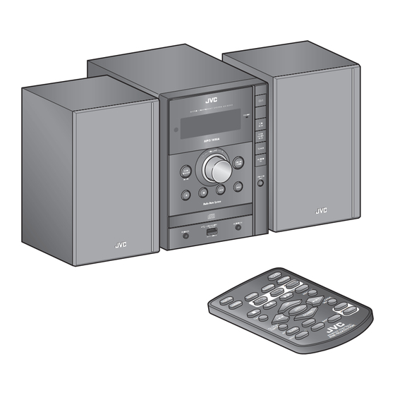
SERVICE MANUAL
MICRO COMPONENT SYSTEM
SERVICE MANUAL
10
MB699<Rev.003>
2009
UX-G357E, UX-G357EN, UX-G357EV, UX-G357UT,
UX-G355B, UX-G355E, UX-G355EN, UX-G355EV,
UX-G355A, UX-G355US, UX-G355UB, UX-G355UW,
COPYRIGHT © 2009 Victor Company of Japan, Limited
Lead free solder used in the board (material : Sn-Ag-Cu, melting point : 219 Centigrade)
1
PRECAUTION. . . . . . . . . . . . . . . . . . . . . . . . . . . . . . . . . . . . . . . . . . . . . . . . . . . . . . . . . . . . . . . . . . . . . . . . . 1-4
2
SPECIFIC SERVICE INSTRUCTIONS . . . . . . . . . . . . . . . . . . . . . . . . . . . . . . . . . . . . . . . . . . . . . . . . . . . . . . 1-7
3
DISASSEMBLY . . . . . . . . . . . . . . . . . . . . . . . . . . . . . . . . . . . . . . . . . . . . . . . . . . . . . . . . . . . . . . . . . . . . . . . 1-8
4
ADJUSTMENT . . . . . . . . . . . . . . . . . . . . . . . . . . . . . . . . . . . . . . . . . . . . . . . . . . . . . . . . . . . . . . . . . . . . . . . 1-11
5
TROUBLESHOOTING . . . . . . . . . . . . . . . . . . . . . . . . . . . . . . . . . . . . . . . . . . . . . . . . . . . . . . . . . . . . . . . . . 1-11
UX-G355UP, UX-G355UT
(for Europe)
TABLE OF CONTENTS
COPYRIGHT © 2009 Victor Company of Japan, Limited
No.MB699<Rev.003>
2009/10
Advertisement
Table of Contents

Related Manuals for JVC UX-G357UT


Summary of Contents for JVC UX-G357UT
-
Page 1: Table Of Contents
SERVICE MANUAL MICRO COMPONENT SYSTEM MB699<Rev.003> 2009 SERVICE MANUAL UX-G357E, UX-G357EN, UX-G357EV, UX-G357UT, UX-G355B, UX-G355E, UX-G355EN, UX-G355EV, UX-G355A, UX-G355US, UX-G355UB, UX-G355UW, UX-G355UP, UX-G355UT (for Europe) COPYRIGHT © 2009 Victor Company of Japan, Limited Lead free solder used in the board (material : Sn-Ag-Cu, melting point : 219 Centigrade) TABLE OF CONTENTS PRECAUTION. -
Page 2: No.mb699
SPECIFICATION For Europe Amplifier section 60 W (30 W + 30 W) at 6 Ω (10% THD) OUTPUT POWER 6 Ω - 16 Ω Speakers/Impedance Audio input AUDIO IN 500 mV/47 kΩ (at “LEVEL 1”) 250 mV/47 kΩ (at “LEVEL 2“) 125 mV/47 kΩ... - Page 3 For Asia Amplifier section 60 W (30 W + 30 W) at 6 Ω (10% THD) OUTPUT POWER 6 Ω - 16 Ω Speakers/Impedance Audio input AUDIO IN 500 mV/47 kΩ (at “LEVEL 1”) 250 mV/47 kΩ (at “LEVEL 2”) 125 mV/47 kΩ...
-
Page 4: Precaution
SECTION 1 PRECAUTION Safety Precautions (1) This design of this product contains special hardware and voltmeter. many circuits and components specially for safety purpos- Move the resistor connection to each exposed metal es. For continued protection, no changes should be made part, particularly any exposed metal part having a return to the original design unless authorized in writing by the path to the chassis, and measure the AC voltage across... - Page 5 Preventing static electricity Electrostatic discharge (ESD), which occurs when static electricity stored in the body, fabric, etc. is discharged, can destroy the laser diode in the traverse unit (optical pickup). Take care to prevent this when performing repairs. 1.5.1 Grounding to prevent damage by static electricity Static electricity in the work area can destroy the optical pickup (laser diode) in devices such as laser products.
- Page 6 Important for laser products 1.CLASS 1 LASER PRODUCT 5.CAUTION : If safety switches malfunction, the laser is able to function. 2.CAUTION : (For U.S.A.) Visible and/or invisible class II laser radiation 6.CAUTION : Use of controls, adjustments or performance of when open.
-
Page 7: Specific Service Instructions
SECTION 2 SPECIFIC SERVICE INSTRUCTIONS This service manual does not describe SPECIFIC SERVICE INSTRUCTIONS. (No.MB699<Rev.003>)1-7... -
Page 8: Disassembly
SECTION 3 DISASSEMBLY Main body (Used figure are UX-G355E) (3) Remove the four screws C attaching the Rear cabinet. (See Fig.3) 3.1.1 Removing the Rear cabinet (See Fig.1 to 4) (1) Remove the four screws A attaching the Rear cabinet. (See Fig.1) Fig.1 Fig.3... - Page 9 3.1.2 Removing the SMPS board (See Fig.5) (1) Disconnect the connector wires from MCU board connect- CN208 CN210 CN201 ed to connectors of the SMPS board. (2) Remove the four screws D attaching the SMPS board. CN202 CN207 Fig.7 3.1.4 Removing the CD mechanism (See Fig.8 to 10) (1) Disconnect the card wire from Pickup connected to con- nector CN102...
- Page 10 (3) Disconnect the connector wire from Loader board connect- (2) Disengage two hooks b engaged both side of the Front ed to connector CN103 of the CD board. (See Fig.10) cabinet. (See Fig.13) (4) Disconnect the connector wire from Traverse mechanism connected to connector CN104 of the CD mechanism.
-
Page 11: Adjustment
SECTION 4 ADJUSTMENT This service manual does not describe ADJUSTMENT. SECTION 5 TROUBLESHOOTING This service manual does not describe TROUBLESHOOTING. (No.MB699<Rev.003>)1-11... - Page 12 Victor Company of Japan, Limited Audio/Video Systems Division 10-1,1chome,Ohwatari-machi,Maebashi-city,371-8543,Japan (No.MB699<Rev.003>) Printed in Japan...
-
Page 13: Parts List
PARTS LIST UX-G357E,UX-G357EN,UX-G357EV UX-G357UT,UX-G355B,UX-G355E UX-G355EN,UX-G355EV,UX-G355A UX-G355US,UX-G355UB,UX-G355UW UX-G355UP, UX-G355UT MODEL MARK MODEL MARK MODEL MARK UX-G357E UX-G357EN UX-G357EV UX-G355B UX-G355E UX-G357UT UX-G355EN UX-G355EV UX-G355A UX-G355US UX-G355UB UX-G355UW UX-G355UP UX-G355UT * All printed circuit boards and its assemblies are not available as service parts. - Page 14 Exploded view of general assembly and parts list Block No. USB board MCU board Display board...
- Page 15 SMPS board 355US,UW 357/355UT CD board 355B,UB The parts without symbol number are not service.
- Page 16 General Assembly Block No. [M][1][M][M] Symbol No. Part No. Part Name Description Local CD5501081600100 DISPLAY LENS 5501-081600100 A,B,C,D CD5501081000100 DISPLAY LENS 5501-081000100 E,F,G,H,I,J,K,L,M,N CD6024230080200 SCREW 6024-230080200 (x2) A,B,C,D CD6024230080100 SCREW 6024-230080100 (x2) E,F,G,H,I,J,K,L,M,N CD5913081000100 COSMETIC FRAME 5913-081000100 CD6024230080200 SCREW 6024-230080200 (x2) A,B,C,D CD6024230080100...
- Page 17 Symbol No. Part No. Part Name Description Local CD3801000000350 FM TUNER MODULE 3801-000000350 A,B,C,F,G,H CD3801000000360 AM/FM TUNER MODULE 3801-000000360 D,I,J,K,L,M,N CD3801000000370 AM/FM TUNER MODULE 3801-000000370 CD5002081000400 REAR CABINET 5002-081000400 A,B,C,F,G,H CD5002081600101 REAR CABINET 5002-081600101 CD5002081000300 REAR CABINET 5002-081000300 E,I,K,M CD5002081000101 REAR CABINET 5002-081000101...
- Page 18 Electrical parts list MCU board Symbol No. Part No. Part Name Description Local Block No. [0][1] D206 CD1321041480020 DIODE 1321-041480020 A,B,C,E,F,G,H Symbol No. Part No. Part Name Description Local D206 or CD1321041480010 SWITCH DIODE 1321-041480010 A,B,C,E,F,G,H D206 CD1321041480040 DIODE 1321-041480040 D,I,J,K,L,M,N IC201 CD1506780514000 IC...
- Page 19 Symbol No. Part No. Part Name Description Local Symbol No. Part No. Part Name Description Local C266 CD1132227053320 E CAPACITOR 1132-227053320 R215 CD1221242062020 C RESISTOR 1221-242062020 C267 CD1132476053050 E CAPACITOR 1132-476053050 R216 CD1221242062020 C RESISTOR 1221-242062020 C268 CD1121105051020 C CAPACITOR 1121-105051020 R217 CD1221242062020 C RESISTOR...
- Page 20 Symbol No. Part No. Part Name Description Local Symbol No. Part No. Part Name Description Local R364 CD1221102062020 C RESISTOR 1221-102062020 CD1608300025000 TORODIDAL COIL 1608-300025000 R365 CD1221102062020 C RESISTOR 1221-102062020 L205 CD1614330010000 COIL 1614-330010000 R366 CD1221103062020 C RESISTOR 1221-103062020 L206 CD1614330010000 COIL...
- Page 21 Symbol No. Part No. Part Name Description Local Symbol No. Part No. Part Name Description Local D104 CD1321041480020 DIODE 1321-041480020 A,B,C,E,F,G,H C177 CD1132476053060 E CAPACITOR 1132-476053060 D104 or CD1321041480010 SWITCH DIODE 1321-041480010 A,B,C,E,F,G,H C178 CD1132476053060 E CAPACITOR 1132-476053060 D104 CD1321041480040 DIODE 1321-041480040 D,I,J,K,L,M,N...
- Page 22 Symbol No. Part No. Part Name Description Local Symbol No. Part No. Part Name Description Local R171 CD2721101020000 FERRITE BEAD 2721-101020000 A,B,C,E,F,G,H or CD1311002070000 DIODE 1311-002070000 A,B,C,E,F,G,H R171 CD1221220062020 C RESISTOR 1221-220062020 D,I,J,K,L,M,N CD1311002070020 DIODE 1311-002070020 D,I,J,K,L,M,N R172 CD2721101020000 FERRITE BEAD 2721-101020000 A,B,C,E,F,G,H CD1311140070000 DIODE RECTIFIER 1311-140070000 A,B,C,E,F,G,H...
- Page 23 Symbol No. Part No. Part Name Description Local Symbol No. Part No. Part Name Description Local CD1121472143120 C CAPACITOR 1121-472143120 D,I,J,K,L,M,N CD1411385500000 TRANSISTOR 1411-385500000 CD1412080500000 TRANSISTOR 1412-080500000 CD1237105012000 RESISTOR 1237-105012000 A,B,C,E,F,G,H CD1323002400000 Z DIODE 1323-002400000 D,I,J,K,L,M,N CD1237473082000 RESISTOR 1237-473082000 CD1323000680040 Z DIODE 1323-000680040 I,K,M...
- Page 24 Symbol No. Part No. Part Name Description Local Symbol No. Part No. Part Name Description Local JK42 CD3203070225000 MICRO PHONE 3203-070225000 RV506 CD1221203062020 C RESISTOR 1221-203062020 JACK RV507 CD1221471062020 C RESISTOR 1221-471062020 JK42 or CD3203070135010 MICRO PHONE 3203-070135010 A,B,C,E,F,G,H RV508 CD1221471062020 C RESISTOR 1221-471062020...
- Page 25 Symbol No. Part No. Part Name Description Local ZD501 CD1313079270020 Z DIODE 1313-079270020 ZD502 CD1313079560020 Z DIODE 1313-079560020 ZD503 CD1323003510000 Z DIODE 1323-003510000 ZD503 or CD1323384510000 Z DIODE 1323-384510000 A,B,C,E,F,G,H ZD504 CD1323003510000 Z DIODE 1323-003510000 ZD504 or CD1323384510000 Z DIODE 1323-384510000 A,B,C,E,F,G,H ZD505 CD1323003510000 Z DIODE...
- Page 26 Packing materials and accessories parts list Block No. No additional / supplemental order of WARRANTY CARDs are available. Except E,EN,EV 355US,UW 355B,UB E,EN,EV A1,A2,A3,A4 A5,A6,A7,A8 A9,A14,A16 The parts without symbol number are not service. 3-14...
- Page 27 Packing and Accessories Block No. [M][3][M][M] Symbol No. Part No. Part Name Description Local CD7202081000100 INST BOOK 7202-081000100 GER CD7202081000900 INST BOOK 7202-081000900 SPA CD7202081001400 INST BOOK 7202-081001400 RUS CD7202081001900 INST BOOK 7202-081001900 CHI(TAIWAN) CD7202081000300 INST BOOK 7202-081000300 ENG CD7202081000200 INST BOOK 7202-081000200 ENG...
- Page 28 SCHEMATIC DIAGRAMS MICRO COMPONENT SYSTEM UX-G357E, UX-G357EN, UX-G357EV, UX-G357UT, UX-G355B, UX-G355E, UX-G355EN, UX-G355EV, UX-G355A, UX-G355US, UX-G355UB, UX-G355UW, UX-G355UP, UX-G355UT DVD-ROM No.SML2009S2 (for Europe) Lead free solder used in the board (material : Sn-Ag-Cu, melting point : 219 Centigrade) Contents Block diagrams...
- Page 29 In regard with component parts appearing on the silk-screen printed side (parts side) of the PWB diagrams, the parts that are printed over with black such as the resistor ( ), diode ( ) and ICP ( ) or identified by the " " mark nearby are critical for safety.
-
Page 30: Block Diagram
Block diagram System control & Audio Amp section X203 IC202 32.768K EEPROM IC204 SCLK IC212 Speaker POWER AMP E,VOLUME IC104 CD traverse IC101, IC102 X101 Q217,Q218 MOTOR Q207 27MHz mechanism 1V8,3V3 REG IC201 AMP_MUTE DRIVER +9V REG AMP_STBY MICON Q205,Q206 Q202,Q203 POWER ON CD PICKUP... - Page 31 Standard schematic diagrams Smps section FR104 47UF/50V KTA1275A 120uF/200V UF802 S8050C 2302- 285000500 T5AL250V 120uF/200V 47K/2W PVCC 10UH 33/2W 4.7K/0.5W 4 7 2/1KV_M 2200UF/35V 33UH PGND PGND FR107 22UF/50V 470UF/35V -25 V -25V FR104 FR104 DAIN 1N4007 FQPF5N60C 100UF/16V AGND 330UF/16V FR104 0R47/2W...
- Page 32 Main section 1 TO TUNER MODULE TO TUNER MODULE(SI47XX SERIES) +5V_TUNER OPEN (AXIAL) CN201 10-PINS FFC HEADER, 1.25MM C322 OPEN (AXIAL) 47U/16V(L5V) CN213 A+12V OPEN R358 Q202 L211 120R,1/2W (AXIAL) 8550C,TO-92 100UH,AXIAL R357 C321 JK201 +3V6 0.1U(L5V) 33R(L5V) GP1FA553TZ(L5V) 100R R359 RESET R443...
- Page 33 Main section 2 R220 C280 R215 (LP5) IPOD_L IPOD_R R224 C279 R213 (LP5) R203 R229 C278 R214 TUNER_DAB_R C286 R216 TUNER_DAB_L R201 R202 C284 C285 1000P 1000P R227 R228 C295 2U2/16V R200 100R MCU_SDA R437 100R MCU_SCL SUB_L SUB_R C283 22U/16V C281 C282...
- Page 34 Main section 3 R413 A+12V OPEN (1206) C244 R424 R426 R428 0.1U 0R (AM) OPEN 3K9 (L5V) AM_HOP C201 R425 IC214 Z217 R440 R441 1000P (AM) 0R (AM) OPEN OPEN (AXIAL) OPEN OPEN SYNCLK C202 R410 C204 0R (L5V) C209 0R (AM) OPEN C237...
- Page 35 Front section +12V_VFD NOTE: ONLY USED IN ES1/ES2 VFD1 FB501 JVC VFD 35P PH-2.54 FB100R QV505 RV516 RV510 RV513 RV511 8050C, T0-92 RV517 EC510 AC3V5_1 CV512 CV513 QV504 47U/35V 8050C, T0-92 FB513 FILAMENT 3300P 3300P RV512 FB100R QV507 CV501 P[1:16]...
- Page 36 Front jack section AUDIO_IN PHJ_PL-310H LH03 10uH LH04 10uH TC38-103 JK42 CP45 2P/2.5MM FB42 +5V_USB TO SMPS BOARD GND_ESD GND_USB JK43 CP42 3P/2.0MM 5070AS-04 PTC01 USB_DM JK60-075F TO MPEG BOARD USB_DP GND_USB USB-4P CP41 7P/2.0MM LINE_LIN HEADPHONE LINE_GND LINE_RIN TP23 HP_DET TO MCU BOARD FB43...
- Page 37 CD section C190 R169 100U/16V, SHORT(LP5) C189 Q105 0.1U (close to CN107) CN114 (LP5) AP2301GN CHGND 3-PINS HEADER, 2.0MM, 90 DEGREE (USB) CN102 R170 IC109 16-PINS FFC HEADER, 1.0MM, 90 DEGREE APPLE C193 +5VV AUTHENTICATION IC R165 0.1U (LP5) TP59 CN107 20-PINS FFC HEADER, 1.25MM C194...
-
Page 38: Printed Circuit Boards
Printed circuit boards Smps board ( forward side ) Smps board ( reverse side ) (Lead free solder used in the board (material : Sn-Ag-Cu, melting point : 219 Centigrade)) (Lead free solder used in the board (material : Sn-Ag-Cu, melting point : 219 Centigrade)) - Page 39 Main board ( forward side ) Main board ( reverse side ) (Lead free solder used in the board (material : Sn-Ag-Cu, melting point : 219 Centigrade)) (Lead free solder used in the board (material : Sn-Ag-Cu, melting point : 219 Centigrade)) Z211 Z209 Z212...
- Page 40 Front board ( forward side ) Front board ( reverse side ) (Lead free solder used in the board (material : Sn-Ag-Cu, melting point : 219 Centigrade)) (Lead free solder used in the board (material : Sn-Ag-Cu, melting point : 219 Centigrade)) LH01 CK405 FB41...
- Page 41 CD board ( forward side ) CD board ( reverse side ) (Lead free solder used in the board (Lead free solder used in the board (material : Sn-Ag-Cu, (material : Sn-Ag-Cu, melting point : 219 Centigrade)) melting point : 219 Centigrade)) C192 D102 C155...
- Page 42 < M E M O >...
- Page 43 Victor Company of Japan, Limited Audio/Video Systems Division 10-1,1chome,Ohwatari-machi,Maebashi-city,371-8543,Japan Printed in Japan (No.MB699SCH<Rev.003>)
Need help?
Do you have a question about the UX-G357UT and is the answer not in the manual?
Questions and answers