Table of Contents
Advertisement
Advertisement
Table of Contents

Related Manuals for Gigabyte GA-Z170-Gaming K3


Summary of Contents for Gigabyte GA-Z170-Gaming K3
- Page 1 GA-Z170-Gaming User's Manual Rev. 1101 12ME-Z17GAK3-1101R For more product details, please visit GIGABYTE's website. To reduce the impacts on global warming, the packaging materials of this product are recyclable and reusable. GIGABYTE works with you to protect the environment.
- Page 2 GIGABYTE. Changes to the specifications and features in this manual may be made by GIGABYTE without prior notice. No part of this manual may be reproduced, copied, translated, transmitted, or published in any form or by any means without GIGABYTE's prior written permission.
- Page 3 Example: Table of Contents GA-Z170-Gaming K3 Motherboard Layout ..............4 Chapter 1 Hardware Installation ..................5 Installation Precautions ..................5 Product Specifications ..................6 Installing the CPU ....................9 Installing the Memory ..................9 Installing an Expansion Card .................10 Back Panel Connectors ..................10 Internal Connectors ..................12 Chapter 2 BIOS Setup ....................20...
-
Page 4: Table Of Contents
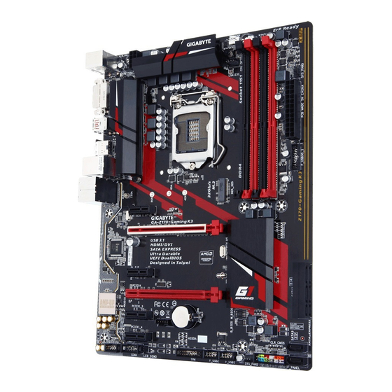
System Information ..................27 BIOS Features ....................28 Peripherals .....................31 Chipset ......................33 Power Management ..................34 Save & Exit .....................36 Chapter 3 Appendix ......................37 Configuring RAID Set ..................37 Drivers Installation ..................39 Regulatory Statements ....................40 Contact ........................4... - Page 5 GA-Z170-Gaming K3 Motherboard Layout Box Contents GA-Z170-Gaming K3 motherboard Four SATA cables Motherboard driver disk I/O Shield User's Manual One G Connector Quick Installation Guide * T he box contents above are for reference only and the actual items shall depend on the product package you obtain.
-
Page 6: Installation Precautions
Chapter Hardware Installation 1-1 Installation Precautions The motherboard contains numerous delicate electronic circuits and components which can become damaged result electrostatic discharge (ESD). Prior installation, carefully read user's manual follow these procedures: • Prior to installation, make sure the chassis is suitable for the motherboard. •... -
Page 7: Product Specifications
Support for non-ECC Un-buffered 1Rx8/2Rx8/1Rx16 memory modules Support for Extreme Memory Profile (XMP) memory modules ( Go to GIGABYTE's website for the latest supported memory speeds and memory modules.) Onboard Integrated Graphics Processor-Intel ® Graphics support: Graphics... - Page 8 Support HDMI version. Maximum shared memory of 512 MB Realtek Audio ® ALC1150 codec High Definition Audio 2/4/5.1/7.1-channel Support for S/PDIF ™ Rivet Networks Killer E2400/2201 chip (10/100/1000 Mbit) Expansion Slots Express x16 slot, running at (PCIEX16)
- Page 9 - 9 -...
- Page 10 Please download the "Windows USB Installation Tool" from GIGABYTE's website and install it before installing Windows 7. ATX Form Factor; 30.5cm x 23.1cm Form Factor * GIGABYTE reserves right make changes product specifications product- related information without prior notice.
-
Page 11: Installing The Cpu
Please visit GIGABYTE's website support lists CPU, memory modules, SSDs, devices. Please visit the Support\Utility List page on GIGABYTE's website to download the latest version of apps. Installing the CPU Read following guidelines before begin install CPU: • Make sure that the motherboard supports the CPU. -
Page 12: Installing The Memory
Enabling Dual Channel memory mode will double the original memory bandwidth. Please visit GIGABYTE's website for details on hardware installation. The four memory sockets are divided into two channels and each channel has two memory sockets as following: Channel A:... -
Page 13: Installing An Expansion Card
1-5 Installing an Expansion Card Read following guidelines before begin install expansion card: • Make sure the motherboard supports the expansion card. Carefully read the manual that came with your expansion card. • Always turn off the computer and unplug the power cord from the power outlet before installing an expansion card to prevent hardware damage. - Page 14 4/5.1/7.1-channel audio configuration. The Mic in jack. Please visit GIGABYTE's website for more software information. • When removing the cable connected to a back panel connector, first remove the cable from your device and then remove it from the motherboard.
-
Page 15: Internal Connectors
1-7 Internal Connectors 1) ATX_12V_2X4 F_AUDIO SPDIF_O CPU_FAN F_USB30_1 4) SYS_FAN1/2/3 F_USB1/F_USB2 CPU_OPT 6) SATA EXPRESS THB_C 7) SATA3 0/1/2/3/4/5 COMA M2A_32G F_PANEL CLR_CMOS Read following guidelines before connecting external devices: • First make sure your devices are compliant with the connectors you wish to connect. - Page 16 1/2) ATX_12V_2X4/ATX (2x4 12V Power Connector and 2x12 Main Power Connector) With the use of the power connector, the power supply can supply enough stable power to all the components on motherboard. Before connecting power connector, first make sure power supply turned off and all devices are properly...
- Page 17 ground wire). speed control function requires the with speed control design. optimum heat dissipation, it is recommended that a system fan be installed inside SYS_FAN1/2/3: CPU_FAN: Definition Pin No. D e fi nition SYS_FAN1 GN D +12 V Sense Speed Control Speed Control Sense SYS_FAN2...
-
Page 18: Set
7) SATA3 0/1/2/3/4/5 (SATA 6Gb/s Connectors) The SATA connectors conform to SATA 6Gb/s standard and are compatible with SATA 3Gb/s and SATA 1.5Gb/s standard. Each SATA connector supports a single SATA device. The Intel ® Chipset supports RAID RAID RAID RAID Refer Chapter... - Page 19 Select proper hole installed and refasten the screw nut. When installing different types SSDs (including SATA SSDs, PCIe SSDs, PCIe SSDs), sure refer supported configurations tables below according to operating mode your SATA controller (AHCI mode RAID mode). • AHCI mode: •...
- Page 20 • PLED/PWR_LED (Power LED, Power Power Switch Speaker Yellow/Purple): Connects to the power status indicator on chassis front panel. when system operating. The off when the system is in S3/S4 sleep state or powered off (S5). • (Power Switch, Red): Connects to the power switch on the chassis front panel.
- Page 21 Definition Definition MIC2_L MIC2_R MIC Power -ACZ_DET LINE2_R Line • The front panel audio header supports HD audio Sense default. FAUDIO_JD • Audio signals will be present on both of the No Pin No Pin front and back panel audio LINE2_L Line connections simultaneously.
- Page 22 Definition Definition VBUS SSRX1- SSRX1+ SSTX2+ SSTX1- SSTX2- 1110 SSTX1+ SSRX2+ SSRX2- VBUS No Pin 13) F_USB1/F_USB2 (USB 2.0/1.1 Headers) The headers conform to 2.0/1.1 specification. Each header provide ports optional USB bracket. For purchasing the optional USB bracket, please contact the local dealer. Definition Definition Power...
- Page 23 SB3V SERIRQ LAD3 LAD2 VCC3 LAD1 SUSCLK 15) THB_C (Thunderbolt ™ Add-in Card Connector) ™ This connector is for a GIGABYTE Thunderbolt add-in card. Definition GPIOA ™ Supports a Thunderbolt add-in GPIOB card. N_-SLP_S3 N_-S4_S5 16) COMA (Serial Port Header) The COM header can provide one serial port via an optional COM port cable.
- Page 24 Turn off your computer and unplug the power cord. Gently remove the battery from the battery holder and wait for one minute. (Or use a metal object like a screwdriver to touch the positive and negative terminals of the battery holder, making them short...
-
Page 25: Startup Screen
<Delete> key during POST when power turned upgrade the BIOS, either GIGABYTE Q-Flash or @BIOS utility. • Q-Flash allows the user to quickly and easily upgrade or back up BIOS without entering the operating system. • @BIOS Windows-based... - Page 26 Function Keys • When the system is not stable as usual, select the Load Optimized Defaults item to set your system to its defaults. • The BIOS Setup menus described in this chapter are for reference only and may differ by BIOS version. 2-2 M.I.T.
- Page 27 M.I.T. Current Status This screen provides information on CPU/memory frequencies/parameters. Advanced Frequency Settings Performance Upgrade (Note) Provides with five different overclocking configurations. Options are: Upgrade, 40% Upgrade, 60% Upgrade, 80% Upgrade, 100% Upgrade. (Default: Auto) CPU Base Clock Allows manually set base...
- Page 28 CPU Clock Ratio Allows you to alter the clock ratio for the installed CPU. The adjustable range is dependent on the CPU being installed. CPU Frequency Displays the current operating FCLK frequency. Frequency for Early Power On Allows FCLK frequency.
- Page 29 Core Current Limit (Amps) Allows current limit Turbo mode. When current exceeds the specified current limit, the CPU will automatically reduce the core frequency in order to reduce the current. Auto sets the power limit according to specifications. (Default: Auto) ...
-
Page 30: Hardware Prefetcher
Package C State Limit (Note 1) Allows you to specify the C-state limit for the processor. Auto lets BIOS automatically configure this setting. (Default: Auto) CPU Thermal Monitor (Note 1) Enables or disables Intel ® Thermal Monitor function, a CPU overheating protection function. - Page 31 (Note This item present only when install memory module that support this feature. System Memory Multiplier Allows you to set the system memory multiplier. Auto sets memory multiplier according to memory SPD data. (Default: Auto) Memory Frequency (MHz) The first memory frequency value normal...
-
Page 32: Channel Interleaving
Channel Interleaving Enables or disables memory channel interleaving. Enabled allows the system to simultaneously access different channels of the memory to increase memory performance and stability. Auto lets the BIOS automatically configure this setting. (Default: Auto) Rank Interleaving Enables or disables memory rank interleaving. - Page 33 Advanced Power Settings CPU Vcore Loadline Calibration Allows configure Load-Line Calibration Vcore voltage. Selecting a higher level keeps the CPU Vcore voltage more consistent with what is set in BIOS under heavy load. Auto lets the BIOS automatically configure this setting sets voltage...
- Page 34 CPU Fan Speed Control (CPU_FAN Connector) Allows you to determine whether to enable the fan speed control function and adjust the fan speed. Normal A llows the fan to run at different speeds according to the CPU temperature. You can adjust the speed with System...
- Page 35 Full Speed Allows the fan to run at full speeds. Fan Speed Percentage Allows control speed. This item configurable only when 2nd System Fan Speed Control is set to Manual. Options are: 0.75 PWM value / 2.50 value 3rd System Fan Speed Control (SYS_FAN3 Connector) Allows you to determine whether to enable the fan speed control function and adjust the fan speed.
-
Page 36: System Information
2-3 System Information This section provides information on your motherboard model and BIOS version. You can also select the default language used by the BIOS and manually set the system time. System Language Selects the default language used by the BIOS. ... -
Page 37: Bios Features
2-4 BIOS Features Boot Option Priorities Specifies overall boot order from available devices. Removable storage devices that support format will prefixed with "UEFI:" string boot device list. boot from operating system that supports GPT partitioning, select device prefixed with "UEFI:"... -
Page 38: Security Option
A password is required for booting the system and for entering the BIOS Setup program. (Default) Full Screen LOGO Show Allows you to determine whether to display the GIGABYTE Logo at system startup. Disabled skips the GIGABYTE Logo when... - Page 39 Partial Initial Part of the USB devices are disabled before the OS boot process completes. (Default) This item configurable only when Fast Boot is set to Enabled. This function is disabled when Fast Boot is set to Ultra Fast. PS2 Devices Support Disabled PS/2 devices...
-
Page 40: Network Stack
LAN PXE Boot Option ROM Allows select whether to enable legacy option controller. (Default: Disabled) This item configurable only Storage Boot Option when CSM Support is set to Enabled. Control Allows select whether enable UEFI legacy option storage device controller. -
Page 41: Ipv6 Pxe Support
Enables disables IPv4 Support. This item configurable only when Network Stack is enabled. Ipv6 PXE Support Enables disables IPv6 Support. This item configurable only when Network Stack is enabled. Administrator Password Allows configure an administrator password. Press <Enter> on this item, type... -
Page 42: Peripherals
cancel password, press <Enter> on password item when requested for password, enter correct first. When prompted for password, press <Enter> without entering any password. Press <Enter> again when prompted to confirm. NOTE: Before setting User Password, sure Administrator Password first. 2-5 Peripherals ... - Page 43 Audio LED Enables or disables the onboard audio function. Disables this function. Still Mode LEDs stay constantly (Default) Beat Mode brightness the LED changes according to music rhythm. Pulse Mode The brightness LED changes slowly smoothly like breath. Legacy USB Support Allows keyboard/mouse used...
- Page 44 Enables or disables the Intel ® BIOS Guard feature, which protects the BIOS from malicious attacks. SATA SATA Controller(s) Configuration Enables disables the integrated SATA controllers. (Default: Enabled) SATA Mode Selection Enables disables RAID SATA controllers integrated in Chipset configures SATA...
-
Page 45: Chipset
2-6 Chipset VT-d (Note) Enables or disables Intel ® Virtualization Technology Directed I/O. (Default: Disabled) Internal Graphics Enables disables the onboard graphics function. (Default: Auto) DVMT Pre-Allocated Allows onboard graphics memory size. Options are: 32M~512M. (Default: 64M) ... -
Page 46: Power Management
Enables or disables High Precision Event Timer (HPET) operating system. (Default: Enabled) IOAPIC 24-119 Entries Enables or disables this function. (Default: Enabled) (Note) This item present only when install that supports this feature. more information about Intel ® CPUs' unique features, please visit Intel's website. -
Page 47: Power On Password
Power On By Keyboard Allows the system to be turned on by a PS/2 keyboard wake-up event. Note: To use this function, you need an ATX power supply providing at least 1A on the +5VSB lead. Disabled Disables this function. - Page 48 Power Loading Enables or disables dummy load. When the power supply is at low load, a self-protection will activate causing it to shutdown or fail. If this occurs, please set to Enabled. Auto lets BIOS automatically configure this setting. (Default: Auto) ...
-
Page 49: Save & Exit
2-8 Save & Exit Save & Exit Setup Press <Enter> on this item select Yes. This saves the changes to the CMOS and exits the BIOS Setup program. Select No press <Esc> return BIOS Setup Main Menu. Exit Without Saving Press <Enter>... - Page 50 Load Profiles If your system becomes unstable and you have loaded the BIOS default settings, you can use this function to load BIOS settings from profile created before, without hassles reconfiguring BIOS settings. First select profile wish load then press <Enter>...
- Page 51 Configuring SATA controller mode BIOS Setup Make sure configure the SATA controller mode correctly system BIOS Setup. BIOS Setup menus, refer Chapter 2, "BIOS Setup," "Integrated Peripherals." Steps: 1. Turn your computer and press <Delete> to enter BIOS Setup during POST (Power- Self-Test).
- Page 52 with SATA SATA hard drive. (Note 2) Refer Chapter 1, "Internal Connectors," "M.2 Socket Connector," configuration tables SATA hard drives SSDs. 4. Under Select Disks item, select hard drives included in RAID array. Press <Space> key hard drives selected (selected hard drives marked with...
-
Page 53: Configuring A
3. Insert the USB thumb drive and then browse to the folder that you previously copied. 4. When a screen as shown, select Intel Chipset SATA RAID Controller and click Next to load the driver and continue the OS installation. Please visit GIGABYTE's website details configuring RAID array. -
Page 54: Drivers Installation
3-2 Drivers Installation • Before installing the drivers, first install operating system. (The following instructions Windows 8.1 example operating system.) • After installing the operating system, insert the motherboard driver disk into your optical drive. Click on message "Tap choose what happens with this... -
Page 55: Regulatory Statements
Contravention will be prosecuted. We believe that the information contained herein was accurate in all respects at the time of printing. GIGABYTE cannot, however, assume any responsibility for errors or omissions in this text. Also note that the information in this document is subject to change without notice and should not be construed as a commitment by GIGABYTE. - Page 56 disposal of electric electronic devices their components. Under Directive, used equipment must marked, collected separately, and disposed of properly. WEEE Symbol Statement The symbol shown below is on the product or on its packaging, which indicates that this product must not be disposed of with other waste. Instead, the device should be taken to the waste collection centers for activation of the treatment, collection, recycling and disposal procedure.
- Page 57 Connect the equipment into an outlet on a circuit different from that to which the receiver is connected. Consult a dealer or experienced TV/radio technician for help. Canada, Industry Canada (IC) Notices / Canada, avis d'Industry Canada (IC) ...
- Page 58 - 58 -...
- Page 59 - 59 -...
- Page 60 - 60 -...
- Page 61 • GIGABYTE eSupport submit technical or non-technical (Sales/Marketing) question, please link http://esupport.gigabyte.com - 61 -...
Need help?
Do you have a question about the GA-Z170-Gaming K3 and is the answer not in the manual?
Questions and answers