Table of Contents
Advertisement
Advertisement
Table of Contents

Related Manuals for BFM Europe Eden Elite


Summary of Contents for BFM Europe Eden Elite
- Page 1 Eden Elite & Avignon Eden Elite HIGH EFFICIENCY INSET LOG EFFECT GAS FIRE Installation, Maintenance & User Instructions Hand these instructions to the user Model No’s BEEL**RN is for use on Natural Gas (G20) at a supply pressure of 20 mbar in G.B. / I.E.
-
Page 2: Table Of Contents
Removal / replacement of the handset battery Checking for flue debris Parts shortlist Section 5 User Instructions Installation Information About your Eden Elite / Eden Avignon Elite gas fire Lighting & operating the appliance 43-45 Cleaning instructions Removal & replacing the glass frame assembly 47-48 Removal &... -
Page 3: Information And Requirements
SECTION 1 INFORMATION AND REQUIREMENTS APPLIANCE INFORMATION Main injector : (1 off) Stereomatic Cat 96 – size 1.95 (NG) Pilot Type : NG - Seagas P5-29D Max. Gross Heat Input : 6.9 kW Min. Gross Heat Input : 2.0 kW Cold Inlet Pressure : 20.0+/-1.0 mbar (8.0 +/- 0.4 in w.g.) Ignition :... -
Page 4: Conditions Of Installation
INSTALLATION REQUIREMENTS CONDITIONS OF INSTALLATION It is the law that all gas appliances are installed only by a GAS SAFE Registered Installer, in accordance with these installation instructions and the Gas Safety (Installation and Use) Regulations 1998 as amended. Failure to install appliances correctly could lead to prosecution. -
Page 5: Shelf Position
SHELF POSITION The fire may be fitted below a combustible shelf providing there is a minimum distance of 300mm above the top of the fire and the shelf does not project more than 150mm. If the shelf overhangs more than 150mm the distance between the fire and the shelf must be increased by 15mm for every 25mm of additional overhang over 150mm. -
Page 6: Fireplace Opening Into Brick Chimney Or Studded Wall
FIRE PLACE OPENING 1.6.1 Fireplace Opening for Engine Only Applications into Brick Chimney The front opening of the fire place must be between 855mm and 875mm wide, between 595mm and 615mm high and 300mm deep. If the opening exceeds these dimensions then a surround must be constructed from suitable non- combustible material to produce a correct size opening. - Page 7 1.6.2 Fireplace Opening for Engine Only Applications into False Chimney Breast (Studwork) All combustible parts of the studwork must be set at the distances as shown below in figure 4 & 5. For installation into such applications a flue box with 125mm flue pipe adaptor is available to purchase as a cost option extra, please order part number 1178-182310, from your local BFM fires stockist.
-
Page 8: Spillage Monitoring System
Fireplace Opening for Avignon Eden Elite Surround into Brick Chimney or Studwork Application If fitting this fire with a surround supplied from BFM Europe then the fireplace opening of width of 855mm minimum to 875mm maximum and height 595mm minimum to 615mm maximum needs to be prepared at a height of 64mm when installed with the Avignon Eden Elite Surround. -
Page 9: Installation Of Fire
SECTION 2 INSTALLATION OF FIRE UNPACKING THE COMBUSTION CHAMBER Carefully lift the combustion chamber out of the carton. Remove the loose item packaging carefully from the pack. Check the contents as listed :- DO NOT UNDER ANY CIRCUMSTANCES USE THIS APPLIANCE IF THE GLASS PANEL IS BROKEN OR NOT SECURELY FIXED TO THE FIREBOX. -
Page 10: Planning The Gas Supply Route
PLANNING THE GAS SUPPLY PIPE ROUTE 2.2.1 Before installing the combustion chamber, decide from which side or if a rear connection to the gas supply is required. Plan the pipe run to enter from the rear or below the firebox from the left, right or rear and connect to the inlet elbow. -
Page 11: Installing The Firebox
2.2.2 The gas supply can be routed into the fire from the centre left hand side, see figure 10 below for dimensional information regarding position and route of gas supply pipe, approximately 100mm in from rear face of fire box with a 90 degree bend in the vertical plane 40mm from the bottom edge of the supply pipe. - Page 12 INSTALLING THE FIREBOX (CONTINUED) 2.3.1 To remove the glass panel, the glass clamp as supplied in the loose items pack will be required. Secure the clamp to the glass panel as shown below in figure 11. Fig. 11 2.3.2 Remove the front grill by removing the 2 off side trims by simply lifting clear (they are retained by magnets).
- Page 13 2.3.3 Remove the 5 off securing screws and glass panel retaining bracket that are located on the top underside face of the combustion chamber. behind the canopy. See figure 13 below. Fig. 13 2.3.4 Lift the glass panel vertically to release from the bottom retaining channel and then tilt forwards as shown below in figure 14 / 15 to release.
- Page 14 2.3.5 Lift the burner tray cover vertically clear as shown below in figure 16 and store in a safe place. Fig. 16 2.3.6 This will allow access to the 2 off burner retaining screws, 1 off at each side as shown below in figure 17. With the 2 off burner screws removed, loosen the screw holding the injector then lift the burner unit clear then remove in a forward direction.
- Page 15 2.3.7 The gas supply cover plate then can be removed via 2 screws as shown below in figure 18. Fig. 18 Gas supply cover plate 2.3.8 Make the gas connection to the inlet elbow as prepared in section 2.5 The burner plate can be removed by removing 6 off screws as shown below in figure 19 to allow the gas supply pipe to be routed.
- Page 16 2.3.10 Remove the pressure test point screw from the inlet elbow and fit a manometer. 2.3.11 Turn on the main gas supply and carry out a gas tightness test as per section 2.4 2.3.12 Fit the batteries to the battery box and handset as per section 3.2 2.3.13 Finish the surface covering around the opening as shown in section 2.5 2.3.14...
- Page 17 2.3.16 The firebox should be secured to the opening using a minimum of 4 off fixings (not supplied) that are suitable for the wall type the fire is being installed into. Below (figure 21) is a diagram to indicate the hole centre positions available on the firebox to facilitate the fixing to the opening.
-
Page 18: Gas Tightness And Inlet Pressure
GAS TIGHTNESS AND INLET PRESSURE THIS APPLIANCE IS INTENDED FOR USE ON A GAS SUPPLY WITH A GOVERNED METER. 2.4.1 Remove the pressure test point screw from the inlet elbow and fit a manometer. 2.4.2 Turn on the main gas supply and carry out a gas tightness test. 2.4.3 See section 3.3 for full details of the operating method for the fire. -
Page 19: Finishing The Product Aperture / Fitting The Plastering Frame
FINISHING OF THE PRODUCT APERTURE / FITTING THE PLASTERING FRAME 2.5.1 The area below around the appliance will require a high temperature plaster finish around the appliance due to the high heat output level of the product, see figure 22. A plastering frame is available as an optional extra to assist in obtaining this finished surface, please order part number 1178-182370. -
Page 20: Installing The Avignon Surround
INSTALLING THE “AVIGNON” SURROUND 2.6.1 Unpack the surround from the wooden crate, check all parts are present as per figure 23 overpage and carefully store the components. 2.6.2 The underside of the hearth should be painted with a weak PVA (8 parts water to 1 part PVA). - Page 21 Fig. 23 - “Avignon” Surround Contents of Avignon surround :- Shelf Top Section L/H Leg Shelf Top Infill Section L/H Infill Section Top Infill Section R/H Infill Section R/H Leg Hearth Panel Bottom Infill Section 1 off hearth panel 1 off R/H leg 1 off L/H leg 1 off R/H infill section 1 off L/H infill section...
-
Page 22: Fitting The Fuel Bed Logset
SECTION 3 INSTALLATION OF FIRE FITTING THE FUEL-BED LOGSET IF FITTING THE PRODUCT WITH THE PEBBLE FUELBED, PLEASE PROCEED TO SECTION 3.2 3.1.1 The vermiculite material should then be first layed around the burner tray as shown below in figure 24, resulting in an even layer. Fig. 24 Single even layer of vermicilite to be placed all over burner area including burner ports 3.1.2 Place Log “H”... - Page 23 3.1.3 Place Log “G” at the centre left hand side of the burner as shown below in figure 26. Fig. 26 Log “G” 3.1.4 Place Log “F” at the left hand side of the burner tray resting on Log “G” as shown below in figure 27.
- Page 24 3.1.5 Place Log “E” at the left hand side of the burner, resting on Log “F” and Log “H” as shown below in figure 28. Fig. 28 Log “E” 3.1.6 Place Log “D” at the left hand side of the burner tray locating on Log “E” and Log “F”...
- Page 25 3.1.7 Place Log “C” at the right hand rear side of the burner tray as shown below in figure 30. Fig. 30 Log “C” 3.1.8 Place Log “B” to the front right hand side of the burner tray locating on the branch of Log “1”...
- Page 26 3.1.9 Place Log “A” to the centre middle right hand side of the burner tray locating on Log “B” and Log “C” as shown below in figure 32. Fig. 32 Log “A” 3.1.10 Place Log “I” to the centre of the burner tray locating on Log “G” and Log “H”...
- Page 27 3.1.11 Complete a final check to ensure all logs are positioned as shown below in figure 34. Fig. 34 Log “H” Log “D” Log “E” Log “C” Log “I” Log “F” Log “G” Log “A” Log “B” 3.1.11 If required, fit the glow fibre material over the flame ports. To do this, seperate into short strands and place randomly over the flame porting area.
-
Page 28: Fitting The Batteries
FITTING THE BATTERIES 3.2.1 The battery pack is located under the front grill as shown below in figure Fig. 35 Battery box location 3.2.2 Lift battery pack from its retaining bracket, remove rear cover (held in position by screw) and then fit 4 off AA batteries. Replace cover and then re-position battery pack within retaining bracket. -
Page 29: Lighting / Operation Of The Appliance
LIGHTING & OPERATION OF THE FIRE IMPORTANT : IF THE BURNER IS EXTINGUISHED FOR ANY REASON YOU MUST ENSURE THAT YOU WAIT A FULL FIVE MINUTES BEFORE ATTEMPTING TO RE-LIGHT THE FIRE. The fire is controlled by the remote handset supplied with the fire. Ensure the batteries as supplied in the loose items pack have been fitted to the fire and the handset before attempting to light it. - Page 30 3.3.1.2 The remote handset is now used to control all functions of the fire. To light the fire, press the “UP” arrow and and “OFF” button simultateously as shown on figure 37 below. You will hear a click and the fire begins a 30 second ignition process.
- Page 31 3.3.1.4 To turn the fire off, press the “OFF” button, this will extinguish all flames including the pilot. 3.3.2 Operation of the Fire in “TEMPERATURE” mode 3.3.2.1 In order to change the mode of operation from “MANUAL” to “TEMPERATURE”, press the “SET” button, the fire will then change to either “DAY TEMP”...
- Page 32 burner only) until the room has cooled to the temperature you have set on the handset display. 3.3.2.5 If you would like the “NIGHT TEMP” to turn the fire off then decrease the temperature until [----] is displayed. 3.3.3 Operation of the Fire in “TIMER” mode 3.3.3.1 In order to change the mode of operation from “MANUAL”...
- Page 33 3.3.3.4 To set the P2 timed setting, press the “SET” button until the “TIMER” mode is displayed. Hold the “SET” button until the display flashes the current time for P1. Press the “SET” button again to scroll past the setting for P1 (sun) and P1 (moon). The time should now be flashing on the handset.
- Page 34 3.3.5 Low Battery Signal 3.3.5.1 When the battery in the handset needs replacing, “BATT” will be displayed on the handset. 3.3.5.2 Remove the cover on the rear of the handset and replace the 9V battery as necessary. 3.3.6 To Set the Time on the Remote Handset 3.3.6.1 Simultanelously press the “UP”...
-
Page 35: Checking For Clearance Of Combustion Products
CHECKING FOR CLEARANCE OF COMBUSTION PRODUCTS 3.4.1 Close all doors and windows in the room. 3.4.2 Light the fire and allow to run for approximately 5 minutes on high position. 3.4.3 After approximately 5 minutes hold a smoke match just inside and below the centre of the lower front canopy at the top of the fire (see figure 43 below). -
Page 36: Removal / Re-Fitting Of The Efficiency Baffle
REMOVAL / RE-FITTING OF THE EFFICIENCY BAFFLE 3.5.1 Remove the glass panel as shown in section 2.3.1 to 2.3.4 3.5.2 The efficiency baffle is provided in the loose items pack and fitted to the inner roof of the combustion chamber, secured by 2 off screws. 3.5.3 Remove / replace the screws as necessary and fit or remove the efficiency baffle onto the appliance as shown below in figure 44. -
Page 37: Maintenance
SECTION 4 MAINTENANCE Servicing Notes Servicing should be carried out annually by a competent person such as a GAS SAFE registered engineer. This is a condition of the guarantee schemes. The service should include visually checking the chimney and fire opening for accumulations of debris and a smoke test to check for a positive up-draught in the chimney. -
Page 38: Removal Of The Receiver Unit / Control Board
Removing the receiver unit / control board. 4.3.1 Remove the burner from the combustion chamber as described in section 4.1. 4.3.2 Disconnect the control wires from the receiver unit / control board. 4.3.3 Disconnect the ignition wire. 4.3.4 Re-fit the new receiver and re-fit the control wires to the control valve. 4.3.5 Re-assemble the burner unit to the combustion chamber and carry out a gas tightness test. -
Page 39: Parts Shortlist
Parts Shortlist GV60 gas control valve B-92200 GV60 receiver unit B-153140 GV60 thermostatic handset B-148120 Handset wall bracket B-126410 Battery pack B-110160 ODS / Pilot B-128100 Glass panel B-179760 Complete log set B-184070 Log A only B-184390 Log B only B-184410 Log C only B-184400 Log D only... -
Page 40: 5.1 Installation Information
The Model number of this appliance is as stated on the rating plate affixed to the control panel of the fire and the appliance is manufactured by:- BFM Europe Ltd Trentham Lakes Stoke on Trent... -
Page 41: About Your Eden Elite / Eden Avignon Elite Gas Fire
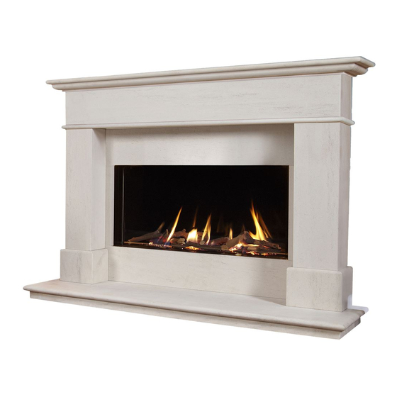
ABOUT YOUR NEW EDEN ELITE AND EDEN AVIGNON ELITE GAS FIRE The BFM Fires “Eden Elite / Eden Avignon Elite” log effect gas fires incorporate a unique and highly developed fuel bed which gives the realism of a loose log layout combined with realistic flames and glow. - Page 42 LIGHTING THE APPLIANCE IMPORTANT : IF THE BURNER IS EXTINGUISHED FOR ANY REASON YOU MUST ENSURE THAT YOU WAIT A FULL FIVE MINUTES BEFORE ATTEMPTING TO RE-LIGHT THE FIRE. The fire is controlled by the remote handset supplied with the fire. Ensure the batteries as supplied in the loose items pack have been fitted to the fire and the handset before attempting to light it.
-
Page 43: Lighting & Operating The Appliance
Fig. 2 Manual Graphic on Handset Display 5.3.1.3 With the product in “MANUAL” mode the fire can now be switched between HIGH rate heat input and LOW rate heat input by pressing the “DOWN” arrow on the handset. To reduce the flame height of the main burner incrementally, press the arrow momentarily. - Page 44 5.3.2 Operation of the Fire in “TEMPERATURE” mode 5.3.2.1 In order to change the mode of operation from “MANUAL” to “TEMPERATURE”, press the “SET” button, the fire will then change to either “DAY TEMP” (figure 4) mode or “NIGHT TEMP” mode (figure 5). To alternate between the 2, press the “SET”...
- Page 45 5.3.3 Operation of the Fire in “TIMER” mode 5.3.3.1 In order to change the mode of operation from “MANUAL” to “TIMER”, press the “SET” button, the fire will then alternate between the settings until the “TIMER” mode is displayed. NOTE : The “SET” button allows you to alternate between all modes of operation :- “...
-
Page 46: Cleaning Instructions
Any damaged parts must be replaced by contacting your dealer or telephoning BFM Europe on the number stated on the rear cover of this book. Logs or pebbles must only be replaced with a complete and genuine replacement set and the fire must never be run with the wrong number or damaged logs or pebbles. -
Page 47: Removal & Replacing The Glass Frame Assembly
REMOVING AND REPLACING THE GLASS PANEL 5.5.1 To remove the glass panel, the glass clamp as supplied in the loose items pack will be required. Secure the clamp to the glass panel as shown below in figure 8. Fig. 8 5.5.2 Remove the front grill by firstly removing the side trims by simply lifting clear (they are retained by magnets) this will allow the front grill to be... - Page 48 5.5.3 Remove the 5 off securing screws and glass panel retaining bracket that are located on the top underside face of the combustion chamber. behind the canopy. See figure 10 below. Fig. 10 5.5.4 Lift the glass panel vertically to release from the bottom retaining channel and then tilt forwards as shown below in figure 11 / 12 to release.
-
Page 49: Removal & Re-Fitting The Fuel-Bed Logset
REMOVAL AND REPLACING THE FUEL-BED LOGSET Remove the glass panel as shown on pages 47-48 before attempting to remove or replace the logs. 5.6.1 The vermiculite material should then be first layed around the burner tray as shown below in figure 13, resulting in an even layer. Fig. - Page 50 5.6.3 Place Log “G” at the centre left hand side of the burner as shown below in figure 15. Fig. 15 Log “G” 5.6.4 Place Log “F” at the left hand side of the burner tray resting on Log “G” as shown below in figure 16.
- Page 51 5.6.5 Place Log “E” at the left hand side of the burner, resting on Log “F” and Log “H” as shown below in figure 17. Fig. 17 Log “E” 5.6.6 Place Log “D” at the left hand side of the burner tray locating on Log “E” and Log “F”...
- Page 52 5.6.7 Place Log “C” at the right hand rear side of the burner tray as shown below in figure 19. Fig. 19 Log “C” 5.6.8 Place Log “B” to the front right hand side of the burner tray locating on the branch of Log “1”...
- Page 53 5.6.9 Place Log “A” to the centre middle right hand side of the burner tray locating on Log “B” and Log “C” as shown below in figure 21. Fig. 21 Log “A” 5.6.10 Place Log “I” to the centre of the burner tray locating on Log “G” and Log “H”...
- Page 54 5.6.11 Complete a final check to ensure all logs are positioned as shown below in figure 23. Fig. 23 Log “H” Log “D” Log “E” Log “C” Log “I” Log “F” Log “G” Log “A” Log “B” 5.6.12 If required, fit the glow fibre material over the flame ports. To do this, seperate into short strands and place randomly over the flame porting area.
- Page 55 Log I only B-184370 Glow Fibre B-120070 Vermiculite CV-107116 Battery Pack B-110160 Part No. B-184090 Issue 2 BFM Europe Ltd. Trentham Lakes Stoke-on-Trent Staffordshire ST4 4TJ www.bfm-europe.com Telephone - General Enquiries : (01782) 339000 Telephone - Service : (01782) 339008...
Need help?
Do you have a question about the Eden Elite and is the answer not in the manual?
Questions and answers