JVC TH-S9 Service Manual
Hide thumbs
Also See for TH-S9:
- Instructions manual (142 pages) ,
- Manual de instrucciones (96 pages) ,
- Instructions manual (48 pages)
Advertisement
SERVICE MANUAL
DVD DIGITAL CINEMA SYSTEM
6
2004
MB236
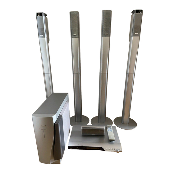
TH-S9,TH-S8,TH-S7
SP-THS9F
SP-THS9S
SP-THS9C
XV-THS9
SP-PWS7
SP-THS9C
SP-THS7F
SP-TH7S
XV-THS7
1
PRECAUTION. . . . . . . . . . . . . . . . . . . . . . . . . . . . . . . . . . . . . . . . . . . . . . . . . . . . . . . . . . . . . . . . . . . . . . . . . 1-4
2
SPECIFIC SERVICE INSTRUCTIONS . . . . . . . . . . . . . . . . . . . . . . . . . . . . . . . . . . . . . . . . . . . . . . . . . . . . . . 1-8
3
DISASSEMBLY . . . . . . . . . . . . . . . . . . . . . . . . . . . . . . . . . . . . . . . . . . . . . . . . . . . . . . . . . . . . . . . . . . . . . . . 1-9
4
ADJUSTMENT . . . . . . . . . . . . . . . . . . . . . . . . . . . . . . . . . . . . . . . . . . . . . . . . . . . . . . . . . . . . . . . . . . . . . . . 1-26
5
TROUBLESHOOTING . . . . . . . . . . . . . . . . . . . . . . . . . . . . . . . . . . . . . . . . . . . . . . . . . . . . . . . . . . . . . . . . . 1-30
SP-THS9F
SP-PWS9
SP-THS9C
TH-S9
SD card
TABLE OF CONTENTS
COPYRIGHT © 2004 Victor Company of Japan, Limited
SP-THS9S
SP-PWS8
XV-THS8
TH-S8
TH-S7
TH-S9
Area suffix
B ------------------------------ U.K.
E ---------- Continental Europe
EN ----------- Northern Europe
EV ------------- Eastern Europe
TH-S8
Area suffix
B ------------------------------ U.K.
E ---------- Continental Europe
EN ----------- Northern Europe
TH-S7
Area suffix
E ---------- Continental Europe
EN ----------- Northern Europe
EV ------------- Eastern Europe
No.MB236
2004/6
Advertisement
Table of Contents


Need help?
Do you have a question about the TH-S9 and is the answer not in the manual?
Questions and answers