Table of Contents
Advertisement
Quick Links
Advertisement
Chapters
Table of Contents

Related Manuals for Remos GX


Summary of Contents for Remos GX
- Page 1 Pilot Operating Handbook including Flight Training Supplement Rev. 02 / July 2009...
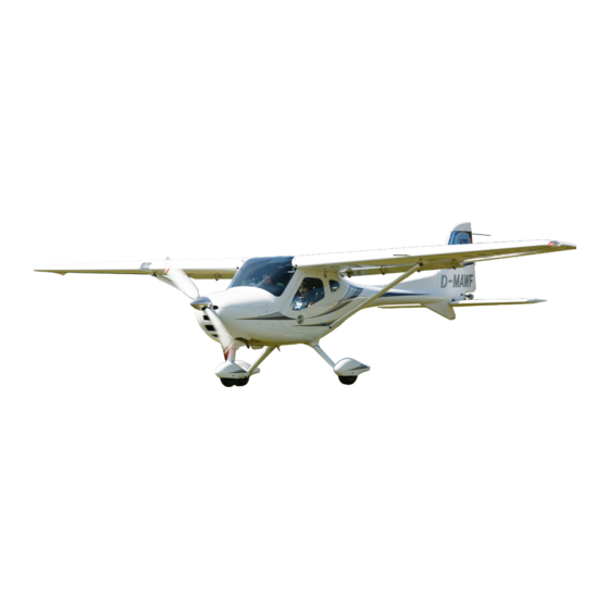
- Page 2 Rev. 02 – July 16 , 2009 Introduction Aircraft Data Light Sport Aircraft REMOS GX The REMOS GX was manufactured in accordance with the Light Sport Aircraft airworthiness standards and does not conform to standard category airworthiness requirements. Serial No.:...
- Page 3 Rev. 02 – July 16 , 2009 Introduction List of Effective Pages This POH consists of the following listed pages and sections. You will find a marking, indicating the revision and date of issue at the top border of each page. Insert latest changed pages, destroy superseded pages.
- Page 4 Rev. 02 – July 16 , 2009 Introduction Remarks and Alterations Applied Modifications Please make a notation below, if any changes have been made to this manual or to the plane. This manual is an important documentation for pilots in command to ensure a safe operation of the aircraft.
- Page 5 Rev. 02 – July 16 , 2009 Introduction Remarks and Alterations Applied Modifications (continued) Pos. Page Concern Date Signature Introduction – iv...
- Page 6 Rev. 02 – July 16 , 2009 Introduction Table of Contents General Information about this Handbook This Flight Operation Handbook is divided into several chapters. The structure of this handbook complies with the Light Sport Aircraft airworthiness standards. Section Description Page General Information 1-1 thru 1-3...
- Page 7 Rev. 02 – July 16 , 2009 Introduction Views The REMOS GX is designed as full composite carbon fiber aircraft. Wingspan 30,6 ft Overall Length 21,3 ft Introduction – vi...
-
Page 8: Paragr. Description Page
Rev. 02 – July 16 , 2009 General Information Table of Contents Paragr. Description Page Introduction Certification Quick Reference Technical Specifications General Information 1 - 1... - Page 9 Introduction This Operation Handbook is designed to help enable a safe and successful completion of each flight with the REMOS GX. It provides you with all necessary information for regular maintenance and operation of the aircraft. Therefore we recommend that the pilot keeps this Operating Handbook upgraded with the newest information available.
- Page 10 Rev. 02 – July 16 , 2009 General Information Technical Specifications Specifications posted below are related with an MTOM of 1.320 lb. Wingspan 30,6 ft Overall Length 21,3 ft Height 7,5 ft Wing area 118,0 ft² Wing load 11,18 lb/ft² Wing chord 4,06 ft General Information 1 - 3...
- Page 11 Rev. 02 – July 16 , 2009 Airplane and Systems Descriptions Table of Contents Paragr. Description Page Engine Propeller, Gearbox Fuel and Fuel Capacity Engine Oil, Coolant Operating Weights and Loading Cockpit Overview Basic Instrumentation Control Panel Electric Fuses 2.10 Cockpit Lighting 2.11 Dual Throttle, Oil Temp Control, …...
- Page 12 Rev. 02 – July 16 , 2009 Airplane and Systems Descriptions Engine Manufacturer: Bombardier-Rotax Engine type: 912 UL-S * Max. power: at take-off: 73,6 kW / 100 hp permanent: 69,9 kW / 95 hp Max. rpm: at take-off: 5.800 rpm. permanent: 5.500 rpm.
-
Page 13: Fuel And Fuel Capacity
Rev. 02 – July 16 , 2009 Airplane and Systems Descriptions Fuel and Fuel Capacity Permissible fuel qualities: Premium Unleaded Auto Fuel (min. 91AKI) 100 LL Aviation Fuel Useable fuel capacity: 21 gallons Total fuel capacity: 22 gallons Engine Oil, Coolant Engine oil: Automotive engine oils * Engine oil capacity:... - Page 14 Cockpit Overview Cockpit example The following pages will give you more information about how to operate your REMOS GX. Note: Some of the illustrated devices or options may not be available, due to the regulations of the ASTM standard. Please...
- Page 15 (not for ASTM aircraft certified in USA). The basic equipment of your REMOS GX consists of the following instruments: ASI, VSI, Altimeter, Slip Indicator and an analog Tachometer. Optional it is possible to equip the aircraft with an electric artificial Horizon, Directional Gyro, Turn and Bank Indicator.
- Page 16 , 2009 Airplane and Systems Descriptions Electric Fuses The electrical system of the REMOS GX consists of a Master- Bus system, which allows installation of additional equipment very easily. The Master-Bus is separated into Master and Avionics circuits, each populated by 6 automatic circuit breakers.
-
Page 17: Cockpit Lighting
, 2009 Airplane and Systems Descriptions 2.10 Cockpit Lighting The REMOS GX cockpit does feature an effective LED panel lighting system, which can be dimmed independently from the instrument lights. It is a dazzle-free system designed for Night- VFR use. - Page 18 Rev. 02 – July 16 , 2009 Airplane and Systems Descriptions 2.11 Dual Throttle, Oil Temperature Control, Additional Terminals Two extension panels are located to the left and to right of the cockpit frame which are used as follows: Left Panel At the upper position the oil temperature control is installed.
- Page 19 Rev. 02 – July 16 , 2009 Airplane and Systems Descriptions 2.12 Center Console The following controls are located on the center console: Choke – green • Carburetor heat – yellow • Fresh air control – blue • Cabin heat – red •...
- Page 20 COMM and NAV equipment. A radio rack for the most popular devices, associated with the REMOS „plug-n-fly“ harnesses allows easy installation of add- on´s and guarantees interference-free operation. The radio rack is held in place by 6 shock mounts to give a maximum protection against vibration.
- Page 21 Rev. 02 – July 16 , 2009 Airplane and Systems Descriptions Configuration A (“Explorer”/“Aviator I”-package with GPS option) This avionics package contains a Garmin SL-40 radio (optional NAV/Comm Garmin SL-30), a Garmin transponder (mode-C transponder GTX-327 or mode-S transponder GTX-328 or GTX- 330), along with the audio-panel Garmin GMA-240.
- Page 22 , 2009 Airplane and Systems Descriptions 2.14 Secondary Instrumentation The right cockpit panel of your REMOS GX is equipped with additional instrumentation, depending on the avionics suite.The basic configuration (“Explorer”) is equipped with an engine monitoring system Dynon EMS-D10. In the “Aviator I” the right panel is empty.
- Page 23 In combination with the optional with HS-34 HSI expansion module the FlightDEK-D180 allows precise electronic navigation flights. In combination with GPS and NAV/COMM the REMOS GX is equipped with a high grade avionic. Please note: !!! IFR-Flights, respectively IMC-Flights, are prohibited !!! The FlightDEK-D180 includes the following functions:...
- Page 24 Rev. 02 – July 16 , 2009 Airplane and Systems Descriptions 2.17 Dynon EFIS-D100 / HS-34 Dynon EFIS-D100 The EFIS D-100 is a so called “Primary Flight Display”, i.e. all common primary flight instruments are shown on the screen. The EFIS D-100 includes the following functions: Airspeed-Indicator, Altimeter, Vertical-Speed-Indicator, Slip- Indicator, Magnetic-Compass,...
- Page 25 Multi Functional Display“. Like the EFIS D-100 it does collect a wide range of engine parameters and additional functions on one display screen. Installed in the REMOS GX, the functions listed below are displayed by the EMS-D120 / EMS-D10: Engine speed •...
- Page 26 Rev. 02 – July 16 , 2009 Airplane and Systems Descriptions 2.19 Inflight Entertainment The right additional panel is equipped with RCA jacks for audio in. For aircrafts equipped with GMA 240 audio panel activate the audio-in signal by pressing “MUSIC” and then select “1”. To adjust volume pull the right knob and rotate it.
- Page 27 Rev. 02 – July 16 , 2009 Operating Limitations Table of Contents Paragr. Description Page Airspeed Limits Cross Wind Limitations Service Ceiling Load Factors Prohibited Flight Maneuvers Center of Gravity Range Permissible Flight Maneuvers Operating Limitations 3 - 1...
- Page 28 Rev. 02 – July 16 , 2009 Operating Limitations Airspeed Limits Speed Description 155 mph Airspeed which shall never Never exceed speed be exceeded (134 kts) Maximum airspeed at 137 mph Maximum speed in level maximum continuous flight (119 kts) power setting 108 mph Maximum airspeed for all...
-
Page 29: Load Factors
Rev. 02 – July 16 , 2009 Operating Limitations Load Factors Safe multiple load range: +4,0 g / -2,0 g Prohibited Flight Maneuvers Flight conditions not IFR flights • permitted: Aerobatics • Tailspin • Flights through or within clouds • Flights in icing conditions •... - Page 30 Rev. 02 – July 16 , 2009 Weight-and-Balance-Information Table of Contents Paragr. Description Page Installed Equipment List Weight and Balance Form Center of Gravity (CG) Range and Determination CG-Calculation Calculation Example CG-Diagram Aircraft Specific Weights Weight and Balance Information 4 - 1...
- Page 31 Rev. 02 – July 16 , 2009 Weight-and-Balance-Information Installed Equipment List To meet the requirements of the LSA airworthiness standard, the listed minimum instrumentation is provided as basic equipment. Airspeed indicator • Altimeter • Compass • RPM gauge • Oil -pressure and -temperature gauge •...
- Page 32 Rev. 02 – July 16 , 2009 Weight-and-Balance-Information Center of Gravity Range and Determination To determine “CG”, put the aircraft on 3 weighing scales, positioned on a level surface. Before weighing, a level wing main chord has to be established (use pads between main wheels and scale beneath). A check-mark (R.P.) on the leading edge of the left wing, adjacent to the wing root is provided to ease examination to level wing main chord - use a flexible clear hose, filled with water as a spirit level.
- Page 33 Rev. 02 – July 16 , 2009 Weight-and-Balance-Information CG-Calculation The following procedure has to be maintained for the correct calculation of the center of gravity “CG”. Moment (lb-Inch) = Weight (lb) x Arm (Inch) Moment Total Center of (lb-Inch) Gravity Weight Total (Inch) (lb)
- Page 34 Rev. 02 – July 16 , 2009 Weight-and-Balance-Information Calculation Example The following example is given to show how to calculate the center of gravity „CG“. Weight Moment Inch lb-Inch Empty Weight 12.5* 8,375 Occupants 1,452.5 Fuel 37.8 4,536 Baggage 37.4 1,122 Weight Total: Moment Total:...
- Page 35 Rev. 02 – July 16 , 2009 Weight-and-Balance-Information CG-Diagram Aircraft Specific Weights Below the aircraft specific data shall be notified. Pilots must use this information to ensure a correct weight and balance calculation prior to every flight. This is essential for a safe conduction of each flight. Empty Weight: Maximum Take-Off Weight: Maximum Payload:...
- Page 36 Rev. 02 – July 16 , 2009 Performance Table of Contents Paragr. Description Page Flight Condition T/O Distance Effected by External Circumstances Cruise Speeds, RPM, Fuel Consumption, Range Performance 5 - 1...
- Page 37 Rev. 02 – July 16 , 2009 Performance Flight Conditions Description 80 hp engine 100 hp engine Propeller Tonini Tonini Never exceed speed V Airspeed for best angle of climb V Airspeed for best rate of climb V Maximum climb rate 1180 Rate of descent at idle Airspeed for best gliding...
- Page 38 Rev. 02 – July 16 , 2009 Performance Description 100 hp engine Propeller Sensenich Neuform Rospeller (**) Never exceed speed Airspeed for best angle of climb V Airspeed for best rate of climb V Maximum climb rate 1280 1280 1575 Rate of descent at idle Airspeed for best...
- Page 39 Rev. 02 – July 16 , 2009 Performance Take-Off Distance Effected by External Circumstances Determined data apply for ISA conditions and a dry, hard runway surface. Various circumstances have an effect on take-off and landing performance. According to ICAO-circular 601AN/55/2 it is recommended to use following add-ons on roll- and air distances: Description On roll distance for dry grass...
- Page 40 Rev. 02 – July 16 , 2009 Performance Cruise Speed, RPM, Fuel Consumption, Range Rotax 912 UL, 80 hp engine, Tonini Fixed Pitch Prop Engine Fuel True Maximum Maximum Speed Consumption Airspeed Endurance Range 3.000 ft, mph / kts 5.400 107 / 93 5.200 103 / 90...
- Page 41 Rev. 02 – July 16 , 2009 Performance Rotax 912 UL-S, 100 hp engine, Neuform Ground Adjustable Prop Engine Fuel True Maximum Maximum Speed Consumption Airspeed Endurance Range 3.000 ft, mph / kts 5.400 130 / 113 5.200 123 / 107 5.000 117 / 102 4.800...
- Page 42 Rev. 02 – July 16 , 2009 Emergency Procedures Table of Content Paragr. Description Page Door Emergency Jettison Recovering from Stall Recovery System Operating the Recovery System Illustrated Rescue System Installation Engine Failure / Loss of Power before Take-Off Engine Failure after Take-Off Engine Failure in Flight Emergency Landing Procedure 6.10...
- Page 43 Rev. 02 – July 16 , 2009 Emergency Procedures These sections will all the procedures which have to be applied in case of an emergency or another dangerous situation. You will also get important information regarding the use of the recommended recovery system.
- Page 44 Rev. 02 – July 16 , 2009 Emergency Procedures Attention: It is prohibited to make changes or modifications on any part of the recovery system. Follow the recommendations published by the manufacturer of your installed system and pay special attention to the maintenance intervals. Before each flight remove the securing pin at the emergency handle of the recovery system so the system is ready for use in case of an emergency.
-
Page 45: Engine Failure In Flight
Rev. 02 – July 16 , 2009 Emergency Procedures Engine Failure / Loss of Power before Take-Off If any trouble regarding engine power is determined during taxiing or take-off run, the following procedures shall be applied: Pull throttle lever to idle position •... - Page 46 3. Touch down into the wind, if at all possible 6.10 Glide Ratio The glide ration of the REMOS GX is about 1:10 with flaps retracted and an airspeed of 75mph (65kts). The following table shows, what distances can be flown in gliding configuration (engine shut-off) from different altitudes in a no-wind condition and a clean and dry aircraft.
- Page 47 Rev. 02 – July 16 , 2009 Emergency Procedures 6.12 Emergency Landing on Water 1. The final approach has to be carried out into the wind 2. Cut-off the ignition and close fuel valve 3. Jettison doors 4. Touch down on the water surface with minimum possible airspeed 5.
- Page 48 Rev. 02 – July 16 , 2009 Normal Procedures Table of Contents Paragr. Description Page Preflight Check Draining the Fuel System Starting the Engine Taxiing Normal Take-Off Best Angle of Climb Speed (V Best Rate of Climb Speed (V Cruise Approach 7.10 Normal Landing...
- Page 49 Rev. 02 – July 16 , 2009 Normal Procedures This section provides you with all the procedures for normal operation of the aircraft including pre-flight preparations. Preflight Check Before each flight the following checks have to be conducted: Checks outside the aircraft Before moving the aircraft drain possible water from the fuel tank, using the drain valve Check engine oil level (between 1/2 and 1/4 of marking)*...
- Page 50 Rev. 02 – July 16 , 2009 Normal Procedures Preflight Check Before each flight the following checks have to be conducted: Checks inside the aircraft Check aileron quick-fasteners for secure locking Check fuel level Check mounting of rescue system Check that both seats are properly secured in position Close and lock both doors Buckle up Set parking brake...
- Page 51 Rev. 02 – July 16 , 2009 Normal Procedures not use this fuel for flying! After dumping fuel fill up the fuel tank completely. For dumping fuel press in the plastic hose of the drainer and turn it counter-clockwise (seen from bottom) about ¼ of a turn. To close the drainer, turn it back.
- Page 52 3. Check both magnetos – maximum rpm decrease 300 rpm 4. Set engine to idle Taxiing The steerable nosewheel of the REMOS GX allows easy ground handling. Turns of 49 feet in diameter can be conducted easily. The main gear is equipped with hydraulic disc brakes, which are operated by a lever on top of the middle section between the seats.
- Page 53 Rev. 02 – July 16 , 2009 Normal Procedures Normal Take-Off Set flaps to 15° position (Take-off from concrete or hard surface runways can also be done with flaps in retracted position) Adjustable propeller in take off position (Not for ASTM aircraft certified in USA) Set electric trim to neutral position Switch on electric fuel pump Move rudder and elevator to neutral position (in crosswind...
- Page 54 Rev. 02 – July 16 , 2009 Normal Procedures Best Rate of Climb Speed (V The maximum climb rate is achieved at an airspeed of about 75 mph (65 kts). Please monitor CHT, oil and water temperature during long periods of climbing. Oil temperature regulation flap must be set to position "open"...
- Page 55 Rev. 02 – July 16 , 2009 Normal Procedures 7.11 Short Field Take-Off To perform a short field take-off, set flaps to 15° position, apply brakes and move the throttle to the full power position. Release brakes with stick held back. Rotate until nose-gear is off the ground, keep that attitude and wait until the airplane lifts-off by itself.
- Page 56 Rev. 02 – July 16 , 2009 Normal Procedures CG at most forward position (airspeeds as IAS) Flap Position 0° 15° 30° 40° 50 mph 46 mph 44 mph 43 mph at idle min. (43 kts) (40 kts) (38 kts) (37 kts) 47 mph 46 mph...
- Page 57 7.14 Constant Speed Propeller (Not for LSA certified in USA) If your REMOS GX is equipped with a constant speed propeller the rate of climb increases and a lower fuel consumption in cruise flight is realized. According to Rotax maintenance handbook it is permissible to operating the engine between full power and propeller curve without restrictions.
- Page 58 Rev. 02 – July 16 , 2009 Normal Procedures 7.15 T/O and Landing with Constant Speed Prop There are no differences for take off and landing procedures with a constant speed propeller and a fixed pitch propeller. However, please notice the following features: Take-Off procedures: 1.
- Page 59 , 2009 Normal Procedures 7.16 Flying without Doors Flying without doors is allowed for the REMOS GX. To take out the door, follow this procedure: Unlock the door, by rotating back the door lock handle. Disconnect the gas spring on the door (clip-fastener) and place it behind seat backrest.
- Page 60 Rev. 02 – July 16 , 2009 Aircraft Ground Handling and Servicing Table of Contents Paragr. Description Page Servicing Fuel, Oil and Coolant Towing and Tie-Down Instructions 100 hr Service 300 hr Service Cleaning and Care Folding Wing System Preparation for Assembling and Disassembling Connecting folded Wings to Fuselage Installing Horizontal Stabilizer 8.10...
-
Page 61: Aircraft Ground Handling And Servicing
Towing and Tie-Down Instructions Due to the low weight of the REMOS GX it is very easy to move the aircraft on the ground by hand. That’s why there is no special equipment for towing provided. In no case the aircraft shall be towed... - Page 62 The first after sales service has to carried out after 20 hours of flight time. Thereafter, every 100 hours or at least every 12 months the aircraft has to maintained following the REMOS maintenance checklist. Visually check the outer skin of the aircraft for scratches, dents and other damage Change the engine oil (about 0.8 gallon) and the oil filter...
-
Page 63: Cleaning And Care
Aircraft Ground Handling and Servicing 300 hr Service Every 300 hours, the following additional checks/services are required. The aircraft has to maintained following the REMOS maintenance checklist. Exchange brake fluid (use DOT 4 fluid; – aircraft brake fluid must NEVER be used) - Page 64 When the aircraft has to be moved by trailer, please ask your authorized REMOS dealer for advice. When placed on a trailer in a wrong way, serious damage could result.
- Page 65 Insecurely connection, improper operation of control surfaces or insecure locked fasteners will lead to loss of control of the aircraft!! When in doubt contact your local REMOS dealer or service center. Proceed in identical order with the second wing.
- Page 66 Rev. 02 – July 16 , 2009 Aircraft Ground Handling and Servicing Installing Horizontal Stabilizer Like connecting the wings it is recommended to follow this procedure by two persons. One person is needed to hold the stabilizer in place, while the second person applying the two fixing bolts into their bushes through the fuselage tail.
- Page 67 Aircraft Ground Handling and Servicing 8.12 Airframe Servicing The body design of the REMOS GX consists of carbon fiber materials, which ensures extreme strength and a long lifetime of the whole aircraft. Maintenance is reduced to checks of the moving parts such as: locks, hinges and connections.
- Page 68 Aircraft Ground Handling and Servicing 8.13 Main Gear Servicing The REMOS GX is equipped with a steel main gear. As with the fuselage, the main gear requires no regular servicing. The hydraulic hoses of the brake system are located hidden from the strut covers.
- Page 69 Remove the three brake disc fixing screws for separating brake system from wheel (not applicable with the REMOS Brake System installed). Disassembling the brakes – See above. Assembling brakes and wheels Assembling is carried out in reverse order.
- Page 70 , 2009 Aircraft Ground Handling and Servicing Hydraulic brake system The REMOS GX is equipped with the MATCO hydraulic brake system. The brake system operates by a single lever on the center console. This layout allows to control braking performance very precisely while access is granted from both seats.
- Page 71 Aircraft Ground Handling and Servicing 8.15 Nose Gear Servicing The nose gear on the REMOS GX consists of a dip tube, guided by three maintenance-free slide bearings fixed to the fuselage. Rubber spring elements are deferred over the dip tube which carries a wheel fork made from steel at its lower end.
-
Page 72: Propeller Servicing
8.18 Propeller Servicing The standard propellers on the REMOS GX are Sensenich and Neuform. Refer to the propeller manufacturer manuals for servicing information. However, we strongly recommend a visual check for cracks and damage prior to each flight. - Page 73 8.20 Cockpit Panel System The modular cockpit panel system installed into the REMOS GX enables easy access to the installed devices for servicing or alterations. Regardless we strongly recommend to contact an avioncs shop for all electrical belongings.
- Page 74 Rev. 02 – July 16 , 2009 Aircraft Ground Handling and Servicing (3) Now remove both upper cradle retaining screws. (4) The whole radio rack assembly can be swung out of the cockpit frame (5) Pull out the rack and disconnect all harnesses from the installed devices. Assembly Assembling is carried out in reverse order.
- Page 75 Aircraft Ground Handling and Servicing 8.21 Aircraft Structure and Paintwork The whole airframe of the REMOS GX is produced to the latest procedures of carbon fiber composite technique. We only use certified epoxy resins for construction, which guarantees the most possible durability of the aircraft structure.
- Page 76 Rev. 02 – July 16 , 2009 Aircraft Ground Handling and Servicing 8.22 Safety Belts and Harnesses Before each flight check the safety belt for any damage. Cuts, tears and other damage to the belt will greatly reduce its effectiveness. Replace the belt or damaged parts immediately with original spare parts.
- Page 77 Rev. 02 – July 16 , 2009 Required Placards and Markings Table of Contents Paragr. Description Page General Description Airspeed Indicator Range and Markings Information Placards Passenger Warning No Intentional Spins Miscellaneous Placards and Markings Required Placards and Markings 9 - 1...
- Page 78 Rev. 02 – July 16 , 2009 Required Placards and Markings General Description Required placards and markings are created in the following colour code: Inside Outside Information white lettering on a black black lettering on a white background - white framed background - black framed Safety white lettering on a black...
- Page 79 Rev. 02 – July 16 , 2009 Required Placards and Markings All airspeed markings posted in this paragraph does meet the requirement of the ASTM standards. Airspeed Indicator Range and Markings Marking CAS Airspeed / Range Description Minimum airspeed with flaps Red Line, low 44 mph extended...
- Page 80 Rev. 02 – July 16 , 2009 Required Placards and Markings Information Placards The following information placards and markings you will find inside the cabin. Placards Place Cockpit – Left Hand Cockpit – Left Hand Cockpit – Right Hand Cockpit – Right Hand Center Console Required Placards and Markings 9 - 4...
- Page 81 Rev. 02 – July 16 , 2009 Required Placards and Markings Placards Place Center Console Center Console Center Console Center Console Required Placards and Markings 9 - 5...
- Page 82 Rev. 02 – July 16 , 2009 Required Placards and Markings Placards Place Control Panel Right Rocker Panel Baggage Compartments Optional: Constant Speed Prop Control Panel Optional: Glider Towing Aircraft Cockpit – Left Hand Left Rocker Panel Required Placards and Markings 9 - 6...
- Page 83 Rev. 02 – July 16 , 2009 Required Placards and Markings These information placards and markings you will find outside the aircraft. Placards Place Fuel Tank Filler-Cap Wheel Fairings Static-Port Required Placards and Markings 9 - 7...
- Page 84 Rev. 02 – July 16 , 2009 Required Placards and Markings Safety Placards The following safety placards and markings are located inside the cabin. Placards Place Cockpit – Left Hand Cockpit – Right Hand Cockpit – Right Hand Aileron Control Tube Baggage Compartment Baggage Compartment Required Placards and Markings 9 - 8...
- Page 85 Rev. 02 – July 16 , 2009 Required Placards and Markings These safety placards and markings are placed outside the cabin. Placards Place Aileron Elevator Elevator Wing Required Placards and Markings 9 - 9...
- Page 86 Rev. 02 – July 16 , 2009 Required Placards and Markings Warning Placards The following warning placards and markings you will find inside the cabin. Placards Place Center Console Door Door This warning placard is located upper fuselage on the egress area. Placards Place Recovery System...
- Page 87 Rev. 02 – July 16 , 2009 Supplementary Information Table of Contents Paragr. Description Page 10.1 Flight Training Supplement 10.1-1 to 10.1-9 10.2 Towing Glider Supplement 10.2-1 to 10.2-13 Supplementary Information 10 - 1...
-
Page 88: Table Of Contents
Rev. 01 – January 7 , 2008 10.1 Flight Training Supplement Table of Contents Paragr. Description Page Introduction 10.1-2 Take-Off 10.1-3 Climbing 10.1-4 Cruise 10.1-5 Stall 10.1-6 Slip 10.1-6 Gliding 10.1-6 Descent 10.1-7 Approach 10.1-7 Touch Down 10.1-8 Flight Training Supplement 10.1 - 1... -
Page 89: Introduction
10.1 Flight Training Supplement Introduction This chapter should enable you to familiarize yourself with the flight performance and flight characteristics of the REMOS GX. To conduct these instructions you have to refer to the appropriate sections provided by the POH. -
Page 90: Take-Off
Rev. 01 – January 7 , 2008 10.1 Flight Training Supplement Take-Off Take-off under normal conditions 1. After the pre-flight check has been carried out, extend flaps to 15° position. 2. Ensure that the elevator trim is in correct position. 3. -
Page 91: Climbing
Rev. 01 – January 7 , 2008 10.1 Flight Training Supplement Climbing Climbing with Best Rate of Climb With engine set to full power establish V , this is an indicated airspeed of 56 mph (49 kts). At this airspeed the aircraft will achieve the steepest angle of climb. -
Page 92: Cruise
When flying in gusty weather conditions the maximum permissible airspeed of 123 mph (107 kts) should not be exceeded for safety reasons. The REMOS GX offers very stable flight characteristics even in heavy weather conditions, similar to that of a Cessna 172. -
Page 93: Stall
10.1 Flight Training Supplement Stall The REMOS GX is fully controllable when flying at a wide range of airspeeds. At airspeeds below the lower speed limit, the aircraft will display very stable stall characteristics. If the airspeed is reduced by... -
Page 94: Descent
Approach in crosswind conditions Crosswinds will not have a big effect to the flight characteristics of the REMOS GX as long as cross-wind component stays within the maximum demonstrated speed up to 17 mph (15 kts). Performing a crosswind landing will not require above average piloting skills. -
Page 95: Touch Down
Touch Down Touch down under normal conditions Landing the REMOS GX is much easier than landing many other aircraft. The aircraft has very good low speed characteristics and so is very controllable all the way through the landing phase. After a good approach has been conducted the REMOS GX does not require much action to result with a perfect touch down. - Page 96 Rev. 02 – July 16 , 2009 10.2 Towing Glider Supplement Table of Contents Paragr. Description Page General Information 10.2-3 Introduction 10.2-3 Certification 10.2-3 Quick Reference 10.2-3 Airplane and Systems Descriptions 10.2-4 Cockpit 10.2-4 Operating Limitations 10.2-5 Maximum permissible Towing Speed (V 10.2-5 Maximum Weak Link Strength 10.2-5...
-
Page 97: Paragr. Description Page
Rev. 02 – July 16 , 2009 10.2 Towing Glider Supplement Paragr. Description Page Aircraft Ground Handling and Servicing 10.2-14 Servicing Tow Release Clutch 10.2-14 Required Placards and Markings 10.2-15 Cockpit 10.2-15 Release Clutch 10.2-15 Towing Glider Supplement 10.2 - 2... -
Page 98: General Information
This aircraft shall be operated as towing aircraft Attention: only with a valid license including a glider towing rating. This supplement is to be used in addition to the REMOS GX Pilot Operating Handbook only! Certification The REMOS GX complies to the rules of the Light Sport Aircraft airworthiness standards and does not conform to standard category airworthiness requirements. -
Page 99: Airplane And Systems Descriptions
Airplane and Systems Descriptions Cockpit Inside the cabin of the REMOS GX a tow release handle is installed. You will find that handle located at the left hand side of the pilot seat, coloured yellow. If the handle is pulled out, the tow rope will be released. -
Page 100: Operating Limitations
= 300 daN has to be installed. Maximum Glider Take-Off Weight The maximum permissible take-off weight of the glider to be towed varies with the propeller mounted to the REMOS GX. Following operating limitations may not be exceeded: Propeller Glider Tonini GT-2 1.210 lb... -
Page 101: Weight And Balance Information
Rev. 02 – July 16 , 2009 Weight and Balance General When the aircraft is used for glider towing the weight and balance calculations like in the standard configuration are valid also for towing operation. Concerning payload, there are some restrictions which have to be observed, see also Section 3 within this supplement. -
Page 102: Equipment
The following additional equipment is required for the use as glider towing aircraft: 1 x Tost tow release clutch, type E 85 1 x REMOS mounting frame for tow release clutch 1 x Release handle (colored yellow) 1 x REMOS oil temperature regulation flap... -
Page 103: Performance
Rev. 02 – July 16 , 2009 Performance Take-Off Distances If the REMOS GX is equipped with Sensenich R70EN or Neuform CR3-65 propeller, the following T/O distances from hard surface runway apply: Take-off distance above 50ft obstacle hard surface runway, wind calm, ICAO standard atmosphere... -
Page 104: Take-Off Distances Effected By External Circumstances
Rev. 02 – July 16 , 2009 Performance Take-Off Distances Effected by External Circumstances Various circumstances will have an effect on the take-off distance of the aircraft. The following listing gives you an estimation of the values (subject to ICAO-Circular 601AN/55/2): Description On roll distance for dry grass +20%... -
Page 105: Remarks
Rev. 02 – July 16 , 2009 Performance Remarks Based on the rules of the Light Sport Aircraft airworthiness standards the maximum dimension is defined by the weight of the glider to be towed, without consideration of tower glider aerodynamics. During the flight test with the DG-1000T a maximum permissible glider weight of 1.580 lb has been demonstrated. -
Page 106: Emergency Procedures
Section "Emergency Procedures" included in the REMOS GX Pilot Operating Handbook. Additional Procedures If an unallowable attitude of the glider is determined which could cause an uncontrolled flight situation, the tow rope has to be released immediately. If the glider is located outside an angle of 60°... -
Page 107: Normal Procedures
Rev. 02 – July 16 , 2009 Normal Procedures Preflight Check Check tow release clutch to assure proper function and clean condition. Take-Off During take-off, special care has to be taken that the climb rate and airspeed are adopted are to the required values of the towed glider. Watch your rate of climb immediately after take-off (do not exceed the gliders climb capability)! To maintain permissible water- and oil temperatures during climb... -
Page 108: Descent And Landing
Rev. 02 – July 16 , 2009 Normal Procedures Descent and Landing After the glider has released the rope and prior to descent, it is recommended to close the oil temperature regulation flap (position "closed/warmer"). Special care has to be taken to keep all temperatures within the permissible range. - Page 109 Rev. 02 – July 16 , 2009 Aircraft Ground Handling and Servicing Servicing Tow Release Clutch During regular servicing intervals, the tow release clutch has to be cleaned, lubricated and checked to assure proper operation. A general overhaul of the release clutch has to be conducted after 4 years / 4000 towing operations.
- Page 110 Rev. 02 – July 16 , 2009 Required Placards and Markings Cockpit Inside the cabin of the REMOS GX the following placards are applied, when equipped for towing gliders. Adjacent to the airspeed indicator: Adjacent to the tow release handle:...
- Page 111 Rev. 02 – July 16 , 2009 Imprint Pilot Operating Handbook REMOS GX ASTM Edition Editor, Layout und Graphics: Christian Majunke, Hans Fuchs Flight testing and advisory: Christian Majunke, Josef Sporer, Nikolas Sporer Copyright REMOS Aircraft GmbH Flugzeugbau © REMOS 2007-2009, all rights reserved...
Need help?
Do you have a question about the GX and is the answer not in the manual?
Questions and answers