
Subscribe to Our Youtube Channel
Related Manuals for MITECH MT200


Summary of Contents for MITECH MT200
- Page 1 Ultrasonic Thickness Gauge MT200 User’s Manual MITECH CO., LTD. www.ponpe.com www.mitech-ndt.com...
-
Page 2: Table Of Contents
CONTENTS 1 Overview..............................4 1.1 Product Specifications........................4 1.2 Main Functions...........................4 1.3 Measuring Principle...........................4 1.4 Configuration............................5 1.5 Operating Conditions........................5 2 Structure Feature............................6 2.1 Instrument Appearance........................6 2.2 Parts of the Main Body........................6 2.3 Measurement Screen........................7 2.4 Keypad Definitions.......................... - Page 3 Appendix A Sound Velocities........................20 Appendix B Applications Notes......................21 User Notes..............................23...
-
Page 4: Overview
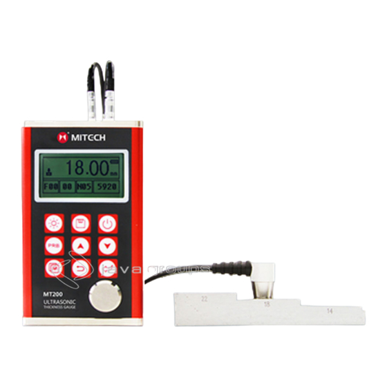
1 Overview The Mitech model MT200 is a digital ultrasonic thickness gauge. Based on the same operating principles as SONAR, the MT200 is capable of measuring the thickness of various materials with accuracy as high as 0.01 millimeters, or 0.001inches. It is suitable for a variety of metallic and non-metallic materials. -
Page 5: Configuration
Where: H-Thickness of the test piece. v-Sound Velocity in the material. t-The measured round-trip transit time. 1.4 Configuration Table 1-1 Item Quantity Note Standard Main body Configur Transducer Model: ation N05/90° Couplant Instrument Case Operating Manual... -
Page 6: Structure Feature
Save/Delete Exit Enter M i Tec h MiTech Inc. Ltd 1 Communication Socket 2 Aluminum Case 3 Belt Hole 4 Battery Cover 5 Keypad 6 LCD Display 7 Socket of Transducer (no polarity) 8 Probe zero disc 9 Aluminum Case 10 Label... -
Page 7: Measurement Screen
2.3 Measurement Screen Battery Info Operating Hint Thickness Read Coupling Status Units Label File Name Sound Velocity Record No./count Transducer Model Battery Information: Display the information of the rest capacity of the battery. Coupling Status: Indicate the coupling status. While the gauge is taking a measurement, the coupling status should be on. -
Page 8: Keypad Definitions
Transducer Model: Current transducer model setting in the instrument Sound Velocity: Current sound velocity setting Thickness Reading : Display present single time measured value. means exceeding upper measuring limit. means lower than bottom measuring limit. - Page 9 Geometry of the transducer. The physical constraints of the measuring environment sometimes determine a transducer’s suitability for a given job. Some transducers may simply be too large to be used in tightly confined areas.
-
Page 10: Condition And Preparation Of Surfaces
Normal Measurement 1.2mm~ Φ20mm× 3.0mm 230.0mm(In Steel) Normal Measurement 1.2mm~ Φ20mm× /90° 3.0mm 230.0mm(In Steel) For thin pipe wall or 0.75mm~ Φ15mm× small curvature pipe 80.0mm 2.0mm wall measurement (In Steel) 30mm For high temperature 3~200mm(In (lower than 300℃) Steel)... -
Page 11: Probe Zero
Use the key and the key to switch to the desired transducer model. Press the key to exit. You can also change the transducer model set by menu operation. Please refer to chapter 5 for the help of menu operation. -
Page 12: Making Measurements
Perform a Probe-Zero. Apply couplant to the sample piece. Press the transducer against the sample piece, making sure that the transducer sits flat against the surface of the sample. The display should show some thickness value, and the coupling status indicator should appear. -
Page 13: Two Point Calibration
In order for the transducer to do its job, there must be no air gaps between the wear-face and the surface of the material being measured. This is accomplished with the use of a “coupling” fluid, commonly called “couplant”. -
Page 14: Scan Mode
Use the key and the key to adjust the displayed thickness up or down, until it matches the thickness of the sample piece. Press the key to confirm. The hint will changes to “NO2”, indicating measuring the second calibration point. -
Page 15: Memory Management
4.11 Memory Management 4.11.1 Storing a reading There are twenty files (F00-F19) that can be used to store the measurement values inside the gauge. At most 99 records can be stored to each file. The following procedures outline this... -
Page 16: Data Printing
4.00 5.01 6.01 record data in the file 7.00 8.01 F00. 4.11.3 Clearing selected files Enter the 【Memory Management】menu screen and highlight the 【Delete by File】 menu item. Then press the key. This function provides the user with the ability to delete the selected data files previously saved in memory. -
Page 17: System Information
Refer to the sketch below during battery replacing. Please pay much attention to the polarity of the battery. Procedure: 1 Power Off the instrument Anode MT200 2 Take off the cover of the battery and take out the two batteries 3 Insert the new batteries... -
Page 18: Menu Operation
5 Menu Operation Both presetting system parameters and the additional function could come true by menu operation. At the measurement screen, press the key into the main menu. Work mode 2-Point Cal Velocity Set Probe Set Tolerance Limit... -
Page 19: Transport And Storage
7 Transport and Storage 1) Keep it away from vibration, strong magnetic field, corrosive medium, dumpiness and dust. Storage in ordinary temperature. 2) With original packing, transport is allowed on the third grade highway. -
Page 20: Appendix A Sound Velocities
Appendix A Sound Velocities Material Sound Velocity in/µs Aluminum 0.250 6340-6400 0.233 Steel, common 5920 0.226 Steel, stainless 5740 0.173 Brass 4399 0.186 Copper 4720 0.233 Iron 5930 0.173-0.229 Cast Iron 4400-5820 0.094 Lead 2400 0.105 Nylon 2680 0.142... -
Page 21: Appendix B Applications Notes
Appendix B Applications Notes Measuring pipe and tubing. When measuring a piece of pipe to determine the thickness of the pipe wall, orientation of the transducers is important. If the diameter of the pipe is larger than approximately 4 inches, measurements should be made with the transducer oriented so that the gap in the wearface is perpendicular (at right angle) to the long axis of the pipe. - Page 22 Suitability of materials Ultrasonic thickness measurements rely on passing a sound wave through the material being measured. Not all materials are good at transmitting sound. Ultrasonic thickness measurement is practical in a wide variety of materials including metals, plastics, and glass. Materials that are difficult include some cast materials, concrete, wood, fiberglass, and some rubber.
-
Page 23: User Notes
Warranty : The product is guaranteed for one year since purchased. Log www.mitech-ndt.com or follow our company official public platform to register for maintenance. Please fill the blanks as required, if the product is not registered for maintenance, it will follow the date of manufacturer.
Need help?
Do you have a question about the MT200 and is the answer not in the manual?
Questions and answers