Advertisement
Available languages
Available languages
Advertisement
Chapters

Related Manuals for Dynacord P 64


Summary of Contents for Dynacord P 64
- Page 1 OWNER’S MANUAL BEDIENUNGSANLEITUNG...
-
Page 2: Table Of Contents
Configuration ..............27 Configuration and testing of an Ethernet connection with P 64......27 Appendix . - Page 3 Konfiguration ..............67 Aufbau und Überprüfung einer Ethernet-Verbindung mit dem P 64 ....67 Anhang .
-
Page 4: Important Safety Instructions
EVI Audio GmbH products: Telex, Dynacord, ElectroVoice, Midas Consoles, KlarkTeknik and RTS. Arrangements are made with the dealer where you purchased the equipment from, for the returning of all unusable equipment at no cost, to the fac- tory in Straubing, for environmental protective disposal. -
Page 5: Introduction
PC Software IRIS-Net - Intelligent Remote & Integrated Supervision. The P 64 Audio Matrix includes up to 32 audio channels, mixer and matrix functions, signal processing and extensive control and monitoring functions. Several P 64 can be connected via a CobraNet™... -
Page 6: P 64 Features
So, various configurations (e.g. 8-in/8-out, 8-in/16-out, 8-in/24-out, 16-in/ 16-out, 24-in/8-out) can be realized in only one single device. In addition, P 64 can be equipped with a CobraNet™ network module. Therefore, several P 64 can be integrated in a network and be connected to a large, sophisticated system. -
Page 7: Unpacking And Warranty
By reading this instruction manual you will get to know many additional features and functions of the P 64. Please read on attentively and keep this manual in order to be able to consult it at any time. -
Page 8: Installation Instruction
Devices with an opposing routing of air flow should not be installed in the same rack. When installing the P 64 in a rack, a free air duct between the sides of the P 64 and the side panel of the rack to the upper rack ventilation must be observed in order to ensure sufficient air ventilation. -
Page 9: Browser Interface
Introduction 1.6 Browser Interface Some of the configuration and operation options of the P 64 which are available in IRIS-Net are also provided by the P 64 browser interface. Any standard Internet browser with activated JavaScript and CSS can be utilized in order to use the browser interface. Please find the detailed information on the P 64 browser interface in the IRIS-Net online help. -
Page 10: Control Elements And Connections
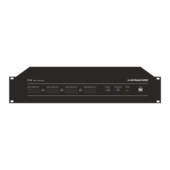
2 Control Elements and Connections 2.1 Front Faceplate The front faceplate of the P 64 has level and status displays and it offers also the possibility to connect a PC via a USB interface. SIGNAL / PEAK-LEDs exist for all 32 audio channels. The channels are combined to groups of 8 and assigned to the audio-slots 1 to 4 at the rear. -
Page 11: System Status-Leds
You can find the necessary USB driver in the subdirectory \Driver\USB Netmax Driver in the IRIS-Net setup directory. Please see chapter Interface description for more information on technical details concerning the USB interface and the other interfaces of the P 64 which are described in the following section. -
Page 12: Rear Panel
ATTENTION: The P 64 has to be switched off if you want to change or install a module. You will find detailed instructions in the data sheet of the corresponding module. Network Module Slot This slot is provided for the installation of a network module, e.g. -
Page 13: Ethernet Interface
Normally this connection is established via a standard (straight throug) Ethernet cable and an Ethernet hub or a switch. If the P 64 is to be connected directly with a computer or another P 64, a crossed Ethernet cable (crossover cable) must be used. -
Page 14: Control Port
The P 64 can be switched on and off with the power switch on the rear of the device. The ON- LED on the front panel is immediately illuminated after switch-on. The P 64 boots and initializes all parameters with those values that had been previously active. -
Page 15: Preparations
CAN interface of the P 64 with the amplifiers. Please see the corresponding chapter CAN Interface on page 18. 7. Switch on the P 64 (via the power switch at the rear), the computer and any additional connected devices, if used. -
Page 16: System Expansion With Analog/Digital Inputs Or Outputs
ATTENTION: It is essential to switch off the P 64 if you want to install or change a module. You will find detailed instructions in the data sheet of the corresponding module. System expansion with analog/digital inputs or outputs There are four slots at the rear of the P 64 which are intended to expand the systems with analogue or digital inputs or outputs. -
Page 17: Interface Description
Amplifiers) can be operated and monitored. By using appropriate network hardware it is even possible to operate the P 64 via a wireless network (WLAN). The Ethernet interface on the rear of P 64 is a RJ-45 connector (8P8C). Both 10Base-T and 100Base-TX Ethernet standards are supported. -
Page 18: Can Interface
10Base-T as well. If the P 64 is connected via a patch cable to a hub/switch, the wiring of the cable at pin 1 of the first connector has to be connected with Pin 1 of the other connector; this is the same regarding the other pins as well. - Page 19 Please see the CAN bus principles chapter on page 36 in the appendix of this document as well as the instruction manuals of the connected devices for further information on CAN bus (especially on system examples and performance specifications). P 64 Digital Audio Matrix Owner’s manual...
-
Page 20: Usb Connection
Accordingly, the low speed (1,5 MBit/s) and full speed (12 MBit/s) transfer rates are supported. According to USB specifications, the cable which is connected to this interface must not be longer than 5 meters. The USB interface of the P 64 is a USB- B (female) connector. -
Page 21: Control Port
The maximum allowable current at the 10 V REF is 100 mA. The following figure shows an example application for the "analogue circuit" on the control inputs of the P 64. A voltage which can be changed via a potentiometer is connected at the control input P 64 Digital Audio Matrix... - Page 22 Preparations 1. The P 64 can be configured via IRIS-Net so that this voltage can be used to adjust a variable parameter, for example, adjusting the volume of an audio input or output. Control port with potentiometer An example for a "digital circuit" on a control input of P 64 is shown in the following figure. The control input 2 is connected to ground via a switch (normally open contact).
-
Page 23: Audio Interfaces
The two left connections of the RELAY OUTPUTS are the READY/FAULT output of the P 64. This floating output is closed when the P 64 is ready for operation and no error has occurred. It is possible in IRIS-Net to configure which kind of error causes the contact to be opened. Due to this feature, this contact is especially suitable for the integration of the P 64 in life safety systems (closed current principle). - Page 24 Digital audio connecting cable It is advisable to choose balanced cables (2 signal conductors + shield) with XLR connectors as digital audio connections. Although all P 64 digital audio inputs can be used unbalanced, balanced audio cable is the better choice.
-
Page 25: Network Configuration
ID 192.168.1 can be retained and • no other devices have the Host-ID 100. If at least one of these three conditions is not fulfilled, the preset IP address of the P 64 has to be changed. P 64 Digital Audio Matrix... - Page 26 The assignment of the IP address can be made via IRIS-Net and via the P 64 browser interface. In IRIS-Net the assignment is possible both over the USB interface and the Ethernet interface of the P 64. Information about the exact proceedings are given in the IRIS-Net online-help.
-
Page 27: Configuration
Configuration and testing of an Ethernet connection with P 64 The purpose of this procedure is to build a connection between a PC and a P 64 with factory network settings (see page 25) via Ethernet and to check the proper function of this connection. - Page 28 The pop-up window Internet Protocol (TCP/IP) Properties appears. 5. Choose the option Use the following IP address in the window. 6. Type 192.168.1.1 in the IP address input field. 7. Type 255.255.255.0 in the Subnet mask input field. P 64 Digital Audio Matrix Owner’s manual...
- Page 29 Please see the Ethernet principles chapter on page 33 in the appendix of this document for more information on the details of connecting devices via Ethernet. 10. Connect the P 64 to the power supply system and switch it on by operating the power switch on the rear.
- Page 30 12. Enter ping 192.168.1.100 and tap the return button. The PC is now checking the connection with the P 64. For this four network packets are sent to the P 64 via Ethernet then the P 64 has to confirm these packets. If the Ethernet connection is successful, no packets get lost.
-
Page 31: Application Example
PC where the IRIS-Net (Intelligent Remote & Integrated Supervision) software is used to operate the P 64 and the remote amplifiers. It is not only possible to operate and control the system via IRIS-Net, but also to monitor the whole system. The P 64 and the PC are connected via Ethernet. -
Page 32: Troubleshootings
Appendix 5.2 Troubleshootings Problem: It is not possible to establish a connection with the P 64 via IRIS-Net. Host not reachable (Timeout) activated? Switch on IP address in unknown IRIS correct? Find out IP online? address Correct IP address PING to IP address... -
Page 33: Ethernet Principles
It is possible that the same IP address is allocated twice if there are more devices in an Ethernet network and if the IP addresses are allocated manually. Switch off the P 64 and try to ping the IP address of the off-state P 64 via a command line prompt (see page 30 of this manual). If the ping is successful, another device has the address of the off-state P 64. -
Page 34: Ip Addresses
Ethernet network. The P 64 uses the TCP/IP protocol, thus, it is an IP network device. IP addresses are used for the logical addressing of devices in an IP network. The P 64 uses version IPv4 (Internet protocol version 4) for the addressing. Therefore, the length of an IP address is 32 bit (= 4 Byte). -
Page 35: Automatic/Manual Allocation Of Ip Addresses
If DHCP is used, certain incidents (e.g. the reboot of a device) can result in the change of the IP address of this device. If this device is a P 64 matrix manager, its configuration in IRIS-Net has to be modified to reflect the changed IP address. For that reason it is not advisable to use DHCP for the dynamic configuration of P 64. -
Page 36: Can-Bus Principles
In general, it does not matter if the bus member is a power amplifier, a P 64 or a UCC1 USB-CAN converter. Thus, the P 64 can be connected at any place of the CAN bus. In total, up to 100 devices can be connected to one CAN bus. - Page 37 In the following figure a star topology from three independent CAN bus systems is given as example. The three CAN buses are connected via two repeaters. P 64 Digital Audio Matrix Owner’s manual...
-
Page 38: System Examples
System with 5 power amps and 1 P 64 at the beginning of the bus. Termination plugs at the P 64 (first unit on the bus) and at amp 5 (last unit on the bus). System with 2 amp-racks and 1 P 64/PC in the middle. Termination plugs at power amp 6 (first unit on the bus) and power amp 12 (last unit on the bus). -
Page 39: Performance Specifications
100 Ω (AWG 24 / AWG 26) can be used for the cabling inside of a rack mounted system. • The previously outlined guidelines for network cabling are mandatory as far as the rack mounted shelve interconnection or fixed installations are involved. P 64 Digital Audio Matrix Owner’s manual... -
Page 40: Ip Address Table
Appendix 5.5 IP Address Table Project: _________________________________ Subnet mask Gateway Device IRIS-Net Device Name Location / Description IP Address P 64 Digital Audio Matrix Owner’s manual... - Page 41 BEDIENUNGSANLEITUNG...
- Page 42 Konfiguration ..............67 Aufbau und Überprüfung einer Ethernet-Verbindung mit dem P 64 ....67 Anhang .
- Page 43 EU-Staaten bitten wir Sie, sich an Ihren örtlichen Händler zu wenden. Wir haben ein eigenes System zur Verarbeitung elektronischer Abfälle und gewährleisten die kosten- freie Entgegennahme aller Produkte der EVI Audio GmbH: Telex, Dynacord, ElectroVoice, Midas Consoles, KlarkTeknik und RTS. Wir haben mit dem Händler, bei dem Sie Ihr Produkt gekauft haben, eine Vereinbarung getroffen, dass alle nicht mehr verwenbaren Geräte zur umweltgerech-...
-
Page 44: Einleitung
Einleitung 1 Einleitung Wir möchten Ihnen zuallererst danken und Sie beglückwünschen, dass Sie sich für die P 64 Audio Matrix von DYNACORD entschieden haben. Um optimale Leistung mit diesem Gerät zu erzielen und um Schäden durch unsachgemäße Bedienung zu vermeiden, lesen Sie bitte diese Bedienungsanleitung aufmerksam durch, bevor Sie den P 64 betreiben. -
Page 45: P 64 Eigenschaften
Charakteristik für die PA-Lautsprecher, Monitor-Lautsprecher, Front Fill Systeme, sowie für die Beschallung von Nebenräumen, Lobby, Angestellten-Bereichen usw. völlig individuell eingestellt und optimiert werden. Anders gesagt, der P 64 meistert jede Anwendung, auch große und komplexe Systeme, absolut exakt und zuverlässig. -
Page 46: Auspacken Und Garantie
Signalisierung bestimmter Zustände verwendet werden können. Der USB Port an der Frontblende des P 64 dient zum Anschluss eines PCs auch im eingebauten Zustand, d.h. wenn der Ethernet-Port womöglich nur schlecht erreichbar ist. Der USB Port kann zur Übertragung einer Datei mit der gesamten P 64-Konfiguration vom P 64 auf den PC bzw. -
Page 47: Installationshinweise
Kaufbeleg und ebenso die Verpackung für eventuelle Rücksendung gut auf. 1.4 Installationshinweise Generell ist der P 64 so aufzustellen oder zu montieren, dass die Luftzufuhr und die Entlüftung an beiden Geräteseiten nicht behindert werden. Die Belüftungsrichtung ist von links nach rechts, wenn man das Gerät von der Frontseite betrachtet. -
Page 48: Browser Interface
1.6 Browser Interface Das P 64-Browser-Interface stellt einen Teil der in IRIS-Net vorhandenen Möglichkeiten zur Konfiguration und Bedienung des P 64 zur Verfügung. Zur Nutzung des Browser-Interface ist jeder herkömmliche Internet Browser mit aktiviertem JavaScript und CSS verwendbar. P 64 Digital Audio Matrix... -
Page 49: Bedienelemente Und Anschlüsse
Eingangs dauernd oder sehr häufig leuchtet, sollten Sie das entsprechende Eingangssignal etwas zurücknehmen. Falls die PEAK-LED eines Ausgangs dauernd aufleuchtet, sollte die interne Verstärkung reduziert werden, da sonst der P 64 permanent übersteuert wird. NETWORK-LEDs Wenn der P 64 an einem Audio-Netzwerk, z. B. CobraNet™, betrieben wird, zeigen diese LEDs den Netzwerk-Status an. -
Page 50: System Status-Leds
Kommunikation über das Audio-Netzwerk statt. Die MASTER-LED leuchtet, wenn der P 64 als Clock-Master – bei CobraNet™ auch als Conductor bezeichnet – fungiert. In einem Audio-Netzwerk gibt es immer nur einen Master, das heißt, die MASTER-LED muss und darf nur an einem P 64 innerhalb des Netzwerk-Verbunds leuchten. -
Page 51: Rückseite
Bedienelemente und Anschlüsse 2.2 Rückseite Auf der Rückseite des P 64 befinden sich sämtliche Anschlüsse für analoge und digitale Audiosignale, Steuer-Schnittstellen und für die Stromversorgung. AUDIO SLOTs Die AUDIO SLOTS 1 – 4 sind Modul-Steckplätze zur Aufnahme von Audio-Modulen. Es stehen sowohl analoge als auch digitale Eingangs- und Ausgangsmodule zur Verfügung. -
Page 52: Ethernet-Schnittstelle
PC und/oder anderen P 64. Normalerweise wird diese Verbindung über ein Standard-Ethernet-Kabel (nicht gekreuzt) und einen Ethernet-Hub oder Switch hergestellt. Wenn ein P 64 direkt mit einem PC oder einem anderen P 64 verbunden werden soll, muss ein gekreuztes Ethernet-Kabel (Crossover-Kabel) verwendet werden. RS-232-Schnittstellen Die beiden RS-232-Schnittstellen dienen zur Verbindung des P 64 mit externen Geräten, z. -
Page 53: Control Port
Sicherung mit identischen Daten für Strom, Spannung und Auslösecharakteristik getauscht werden. Mit dem Netzschalter auf der Geräterückseite wird der P 64 ein- und ausgeschaltet. Nach dem Einschalten leuchtet sofort die ON-LED an der Frontseite. Der P 64 bootet und initialisiert alle Parameter mit den zuletzt eingestellten Werten. -
Page 54: Inbetriebnahme
3.1 Aufbauverfahren 1. Installieren Sie die Erweiterungskarten. Falls Sie für Ihren P 64 Erweiterungskarten (AI-1, MI-1, DI-1, AO-1, DO-1, CM-1, DSP-1 bzw. DSP-2) erworben haben, bauen Sie diese ein. Beachten Sie hierzu den Abschnitt Installation von Erweiterungskarten auf Seite 55 und die Einbauhinweise in den mitgelieferten Bedienungsanleitungen der Erweiterungskarten. -
Page 55: Installation Von Erweiterungskarten
Für die Erweiterung des Systems mit analogen oder digitalen Audioein- bzw. Ausgängen stehen auf der Rückseite des P 64 vier Slots zur Verfügung, diese sind mit AUDIO SLOT 1 bis AUDIO SLOT 4 beschriftet (siehe Seite 51). In diese Slots kann eine beliebige Kombination von Erweiterungskarten folgender Typen eingebaut werden: •... -
Page 56: Erweiterung Der Dsp-Leistung Des Systems
Arbeitsspeicher für ein maximales Delay von 21,8 Sekunden. Sollte dies den Anforderungen ihrer Anwendung nicht genügen, kann durch den Einbau des DSP Extension Moduls DSP-1 oder DSP-2 die Rechenleistung und Speicherkapazität des P 64 erhöht werden. Hierdurch werden die Ausführung komplexerer DSP-Programme und die Verwendung längerer Verzögerungszeiten oder zusätzliche Delay-Lines ermöglicht. -
Page 57: Can-Schnittstelle
10Base-T ist ein Kabel der Kategorie 3 (ungeschirmt, CAT-3), für 100Base-TX ein Kabel der Kategorie 5 (geschirmt, CAT-5) zu verwenden. Bei Anschluss des P 64 mittels eines Patch-Kabels in Verbindung mit einem Hub/Switch ist die Verdrahtung des Kabels eins zu eins, d.h. die Ader des Kabels an Pin 1 des einen Steckers wird mit Pin 1 des anderen Steckers verbunden, für die übrigen Pins wird analog vorgegangen. - Page 58 Inbetriebnahme Zweck liegen dem P 64 zwei Abschluss-Stecker CAN-TERM 120 Ω bei. Stecken Sie diese Abschluss-Stecker in die freien RJ-45 Buchsen des ersten und des letzten Gerätes am CAN- Bus. In der Netzwerk-Verkabelung ist neben dem CAN-Bus auch das symmetrische Audio-Monitor Signal zum Abhören der Endstufeneingänge und -ausgänge mitgeführt.
-
Page 59: Usb-Schnittstelle
(1,5 MBit/s) und Full Speed (12 MBit/s) unterstützt. Das an dieser Schnittstelle angeschlossene Kabel darf laut USB-Spezifikation höchstens 5 Meter lang sein. Bei der USB-Schnittstelle des P 64 handelt es sich um eine Buchse des USB-Typ B (female), die standardgemäße Belegung kann folgender Abbildung und Tabelle entnommen werden. -
Page 60: Rs-232-Schnittstelle
Stoppbit Geschwindigkeit 19200 bit/s In folgender Abbildung und Tabelle sind die im P 64 verwendeten Pins der RS-232-Schnittstelle angegeben. Das zur Verbindung des P 64 mit einem anderen Gerät verwendete Verbindungskabel sollte eine Länge von 15 Meter nicht überschreiten. Belegung RS-232... -
Page 61: Control Port
Steuereingänge Die obere Hälfte, am P 64 mit INPUTS 0-10V beschriftet, stellt vier frei programmierbare Steuereingänge für Spannungen zwischen 0 Volt und 10 Volt zur Verfügung. Die Eingänge sind mit 1 bis 4 durchnummeriert. Der P 64 stellt eine eigene Spannungsversorgung für extern angeschlossene Kontrollelemente, z. - Page 62 In folgender Abbildung ist ein Beispiel zur Verwendung eines P 64 Steuereingangs mit Schaltfunktion dargestellt. Hierbei ist der Steuereingang 2 über einen Schalter (Schließer) mit GND (Masse) verbunden. In IRIS-Net kann der P 64 so konfiguriert werden, dass bei Betätigung des Schalters etwa ein Audio-Eingang oder Audio-Ausgang Kanal stumm geschaltet wird. Die dabei verwendeten Logik-Schwellen für High / Low sind für jeden Eingang frei konfigurierbar.
-
Page 63: Audioschnittstellen
Inbetriebnahme Eine Beispielanwendung zur Beschaltung eines Steuerausgangs ist in folgender Abbildung dargestellt. Hierbei wird über eine Kontrollleuchte ein Betriebszustand des P 64, etwa die Überschreitung eines Temperatur-Grenzwertes, angezeigt. Control Port mit Kontrollleuchte Audioschnittstellen Analoge Audio-Verbindungskabel Als analoge Audio-Verbindung wählen Sie am besten symmetrisch ausgelegte Kabel (2 Signaladern + Schirmgeflecht) mit XLR-Stecker. - Page 64 Inbetriebnahme Digitale Audio-Verbindungskabel Als digitale Audio-Verbindung wählen Sie am besten symmetrisch ausgelegte Kabel (2 Signaladern + Schirmgeflecht) mit XLR-Stecker. Obwohl die digitalen Eingänge des P 64 auch unsymmetrisch belegt werden können, stellt symmetrisch ausgeführtes Audio- Verbindungskabel die bessere Alternative dar.
-
Page 65: Netzwerk-Konfiguration
4 Netzwerk-Konfiguration 4.1 Einführung Der P 64 kann über die Ethernet-Schnittstelle an der Rückseite (siehe Seite 52) an ein TCP/IP- Netzwerk angeschlossen werden. Für Informationen über die Grundlagen von Ethernet und TCP/IP siehe Abschnitt Ethernet-Grundlagen ab Seite 73 im Anhang dieses Dokumentes. - Page 66 IP-Adressen an die einzelnen Geräte vergeben werden. Die Änderung der IP- Adresse kann sowohl über IRIS-Net als auch über das P 64 Browser Interface erfolgen. In IRIS- Net ist die Änderung sowohl über die USB-Schnittstelle als auch die Ethernet-Schnittstelle des P 64 möglich.
-
Page 67: Konfiguration
Netzwerkeinstellung (siehe Seite 65) über Ethernet aufzubauen und die korrekte Funktion der Verbindung zu überprüfen. Es wird im Folgenden davon ausgegangen, dass weder der PC noch der P 64 mit einem bestehenden Ethernet verbunden sind, der P 64 ist vom Stromnetz getrennt. - Page 68 Es erscheint das Dialogfenster Eigenschaften von Internetprotokoll (TCP/IP) 5. Wählen Sie im Fenster die Option Folgende IP-Adresse verwenden. 6. Schreiben Sie in das Eingabefeld IP-Adresse: 192.168.1.1 7. Schreiben Sie in das Eingabefeld Subnetzmaske: 255.255.255.0 P 64 Digital Audio Matrix Bedienungsanleitung...
- Page 69 Für Informationen über Möglichkeiten zur Verbindung von Geräten über Ethernet siehe auch Abschnitt Ethernet-Grundlagen auf Seite 73 im Anhang dieses Dokumentes. 10. Schließen Sie den P 64 an das Stromnetz an und schalten Sie ihn mittels des Netzschalters an der Rückseite ein.
- Page 70 12. Geben Sie ping 192.168.1.100 ein und drücken Sie Return-Taste. Der PC überprüft nun die Verbindung mit dem P 64. Hierzu werden vier Netzwerk-Pakete über das Ethernet an den P 64 verschickt, die von diesem bestätigt werden müssen. Bei erfolgreicher Ethernet-Verbindung werden keine Pakete verloren, in der Ping-Statistik ist daher 0% Verlust angegeben.
-
Page 71: Anhang
5.1 Anwendungsbeispiel Installation in einer Mehrzweckhalle In untenstehender Abbildung ist ein Beispiel für die Verwendung eines P 64 in einer Mehrzweckhalle dargestellt. Hierbei sind als Signalquellen vier Mikrofone, ein CD-Spieler und ein Tuner angeschlossen. Zur Beschallung werden sowohl aktive als auch passive Lautsprecher verwendet. -
Page 72: Problemlösungen
Anhang 5.2 Problemlösungen Problem: Es kann keine Verbindung über IRIS-Net mit dem P 64 aufgebaut werden. Host not reachable (Timeout) nein eingeschaltet? einschalten IP Adresse in nein unbekannt IRIS korrekt? Bestimmung der nein online? zugewiesenen IP Adresse IP Adresse korrigieren... -
Page 73: Ethernet-Grundlagen
Umständen die selbe IP-Adresse doppelt vergeben sein. Um zu überprüfen, ob dies der Fall ist, schalten Sie den P 64 aus und versuchen sie bei ausgeschaltetem P 64 dessen IP- Adresse über ein ping zu erreichen. Falls der ping erfolgreich ist, besitzt ein anderes Gerät die IP-Adresse des P 64. -
Page 74: Ip-Adressen
IP-Netzwerk. In einem IP-Netzwerk werden IP-Adressen zur logischen Adressierung von Geräten verwendet. Der P 64 verwendet die Version IPv4 (Internet Protocol Version 4) zur Adressierung, eine IP-Adresse ist daher 32 Bit (= 4 Byte) lang. Hierdurch sind theoretisch etwa 4,3 Milliarden eindeutige Adressen möglich. -
Page 75: Subnetzmaske
Bei Verwendung von DHCP kann es durch bestimmte Vorkommnisse, etwa dem Neustart eines Geräts, zu einer Änderung der geräteeigenen IP-Adresse kommen. Handelt es sich bei dem Gerät um einen P 64 Matrix Manager, müsste hierbei dessen Konfiguration in IRIS-Net an die P 64 Digital Audio Matrix... -
Page 76: Can-Bus-Grundlagen
Gerät kommunizieren. Dabei ist es grundsätzlich egal, ob der Busteilnehmer eine Endstufe, ein P 64 oder ein UCC1 USB-CAN Converter ist. Somit kann der P 64 an beliebiger Stelle am CAN- Bus betrieben werden. Insgesamt können bis zu 100 Geräte an einem CAN-Bus angeschlossen werden. - Page 77 Durch die Verwendung von einem oder mehreren Repeatern ist neben der oben dargestellten Bus-Topologie auch der Aufbau anderer Netztopologien möglich. Als Beispiel ist in folgender Abbildung eine Stern-Topologie aus drei unabhängigen CAN-Bus-Systemen dargestellt. Die drei CAN-Busse werden hierbei durch zwei Repeater miteinander verbunden. P 64 Digital Audio Matrix Bedienungsanleitung...
-
Page 78: Systembeispiele
System mit 5 Verstärkern und einem P 64 am Bus-Anfang. Abschluss- Stecker am P 64 (Bus-Anfang) und am Verstärker 5 (Bus-Ende). System mit 2 Racks und einem P 64 Matrix Manager in der Mitte. Abschluss- Stecker am Verstärker 6 (Bus-Anfang) und Verstärker 12 (Bus-Ende) -
Page 79: Leitungsspezifikation
Begrenzung dieser Reflexionen sollten diese Stichleitungen bei Datenübertragungsraten bis zu 125 kbit/s eine Einzellänge von max. 2 Meter und bei höheren Bitraten von max. 0,3 Meter nicht überschreiten. Die Gesamtlänge aller Abzweigleitungen sollte 30 Meter nicht übersteigen. P 64 Digital Audio Matrix Bedienungsanleitung... - Page 80 (AWG 24 / AWG 26), wenn es sich nur um kurze Strecken handelt (bis zu 10 Meter). • Für die Verdrahtung der Racks untereinander und in der Gebäudeinstallation sind unbedingt die oben genannten Richtlinien für die Netzwerkverkabelung einzuhalten. P 64 Digital Audio Matrix Bedienungsanleitung...
-
Page 81: Tabelle Ip-Adressen
Anhang 5.5 Tabelle IP-Adressen Projekt: _________________________________ Subnetzmaske Gateway Gerät IRIS-Bezeichnung Standort/Beschreibung IP-Adresse P 64 Digital Audio Matrix Bedienungsanleitung... -
Page 82: Specifications/Technische Daten
Frequency Response 20 Hz...20 kHz (-0.5 dB) Signal to Noise Ratio (A-weighted) AI-1: 117 dB typical AO-1: 118 dB typical P 64 analog In to analog Out: 115 dB typical THD+N < 0.005 % Signal Delay AI-1: 1.3958 ms AO-1: 0.646 ms P 64 analog In to analog Out: 2.2917 ms... - Page 83 Dimensions (W x H x D) 483 x 88.1 x 381 mm (19“, 2 HU) Weight P 64 (without optional modules): 7.35 kg AI-1 Analog Input Module: 200 g AO-1 Analog Output Module: 260 g MI-1 Microphone Input Module: 250 g...
-
Page 84: Block Diagram/Blockschaltbild
RS-232 SDRAM 9-pin D-SUB UART1 Port 1 (16 MByte) RS-232 9-pin D-SUB UART2 Port 2 FLASH (8 MByte) USB Port USB Device USB-Controller Interface Typ B) FRONT PANEL Ethernet (LEDs) RJ-45 Ethernet-Controller Transceiver P 64 Digital Audio Matrix Owner’s manual... -
Page 85: Dimensions/Abmessungen
6.3 Dimensions/Abmessungen P 64 Digital Audio Matrix Owner’s manual... - Page 86 Notes...
- Page 87 Notes P 64 Digital Audio Matrix Owner’s manual / Bedienungsanleitung...
- Page 88 Americas Asia & Pacific Rim Bosch Communications Systems Japan: EVI Audio Japan Ltd. 12000 Portland Ave South 5-3-8 Funabashi, Setagaya-Ku Burnsville, MN 55337, USA Tokyo, Japan 156-0055 USA: Phone:1-800-392-3497 Phone: +81 3-5316-5020 Fax: 1-800-955-6831 Fax: +81 3-5316-5031 Canada: Phone: 1-866-505-5551 China: Bosch Communications Systems Fax:1-866-336-8467...
Need help?
Do you have a question about the P 64 and is the answer not in the manual?
Questions and answers