Table of Contents
Advertisement
Quick Links
Advertisement
Table of Contents

Subscribe to Our Youtube Channel
Related Manuals for F5 VIPRION 4800 Series

Summary of Contents for F5 VIPRION 4800 Series
- Page 1 Platform Guide: VIPRION 4800 Series MAN-0423-05...
-
Page 3: Table Of Contents
Hardware included with the VIPRION 4800 AC chassis..........27 Additional equipment for installing the VIPRION 4800 AC chassis........28 Hardware included with the VIPRION 4800 DC chassis..........28 Additional equipment for installing the VIPRION 4800 Series DC chassis.....28 Hardware included with blades..................29 Peripheral hardware requirements...................29 About installing the chassis....................30... - Page 4 About installing blades.....................44 Removing a blank....................45 Removing a blade....................47 Installing a blade....................48 About powering the VIPRION 4800 Series AC platform..........50 Connecting AC power to the platform..............50 About powering the VIPRION 4800 Series DC platform..........51 Connecting DC power to the platform..............52 Connecting the cables and other hardware..............53...
- Page 5 About repackaging the platform..................91 Repackaging the chassis....................91 Repackaging a blade.......................95 Returned Material Data Security Statement................99 About returned material data security................99 About memory technologies used in F5 equipment............99 Volatile memory.....................99 Battery-backed volatile memory................99 Non-volatile memory.....................99 About removing data from F5 components..............100 Removing sensitive data from storage drives............100...
- Page 6 Table of Contents Legal Notices..........................103 Legal Notices.........................103...
-
Page 7: The Viprion 4800 Series Platform
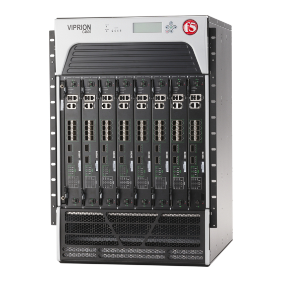
Important: The chassis and blades are shipped in separate boxes. The blades are not designed to be shipped inside a chassis. Although the VIPRION 4800 Series platform is highly extensible and designed to be easy to implement, familiarity with the platform components can help ensure that you install and integrate the platform successfully and effectively. - Page 8 The VIPRION 4800 Series Platform 1. Indicator LEDs (system and power status) 2. LCD display 3. LCD control buttons 4. Blanks for blades 1-8 Figure 1: Front view of a VIPRION C4800 chassis with bezel (with LCD panel) attached The back of the AC-powered chassis includes four AC power receptacles.
- Page 9 Platform Guide: VIPRION 4800 Series 1. Removable lift handle 2. Front lift handle storage 3. Power supply receptacles (1-4) 4. Chassis grounds Figure 2: Back view of the AC chassis The back of the DC-powered chassis includes four DC power block terminals.
- Page 10 The VIPRION 4800 Series Platform 1. Removable lift handle 2. Front lift handle storage 3. DC power block terminals (1-4) 4. Chassis grounds Figure 3: Back view of the DC chassis The DC-powered NEBS chassis includes a decal below the serial number label.
-
Page 11: About The Blades
A blade is the primary component that handles the traffic management within the VIPRION platform. You can install up to eight blades in a VIPRION 4800 Series chassis. These blades comprise a group, known as a cluster. The chassis includes blanks in the slots where blades are not installed. -
Page 12: Using The Lcd Panel
The VIPRION 4800 Series Platform Figure 7: The LCD panel and control buttons Using the LCD panel Put the LCD panel into Menu mode to manage the platform using the LCD menus and control buttons. Press the X button to activate Menu mode for the LCD. -
Page 13: Indicator Leds
Platform Guide: VIPRION 4800 Series Option Description • OFF disables the backlight. Contrast Sets the contrast of the LCD. On Brightness Adjusts LCD backlight brightness. Off Brightness Controls the brightness of the LCD when the backlight is off. System menu You can use the System menu to configure the management interface on both clusters and blades. -
Page 14: Indicator Led Actions
The VIPRION 4800 Series Platform On the blades, the LEDs indicate whether the blade is a primary or secondary blade, and show alarm and blade status. The Alarm LED status for blades is also displayed in the corresponding LED on the LCD panel. -
Page 15: Annunciator Card Indicator Leds
Platform Guide: VIPRION 4800 Series LED action Fan tray status Amber solid Indicates that no firmware application is running (bootloader or application). Can also indicate that the fan tray is not fully seated. Green solid Indicates that the firmware application is running. Can also indicate that voltages, fans, and so on, are within normal limits. -
Page 16: Blade Standard Operating States
The VIPRION 4800 Series Platform Blade standard operating states The blade LEDs indicate the operating state of a blade. ® Note: On power up, the Status LED of each blade turns amber. When the BIG-IP software boots successfully, the Status LED changes to green. -
Page 17: Led Alert Conditions
Platform Guide: VIPRION 4800 Series LED alert conditions The Alarm LED indicates when there is an alert condition on the system. Note: The Alarm LED might continue to display until alerts are cleared using the LCD panel. Action Description System situation... -
Page 18: Platform Interfaces
The VIPRION 4800 Series Platform Platform interfaces Every platform includes multiple interfaces. The exact number of interfaces that are on the system depends on the platform type. Each interface on the platform has a set of properties that you can configure, such as enabling or disabling the interface, setting the requested media type and duplex mode, and configuring flow control. - Page 19 Specifications for fiber SFP+ modules section. Figure 10: An example of a 40 GbE QSFP+ breakout cable ® You can order these 40 GbE QSFP+ components from F5 • QSFP+ breakout cables (MTP to LC), provided as a pair, in these lengths: •...
-
Page 20: About 100Gbe Interfaces
MPO/MTP connectors at both ends. The cable that you use with 100GBASE-LR4 transceiver modules is an industry-standard SMF fiber optic cable with LC duplex connectors and a reach of up to 10km. You must provide your own cable and F5-branded QSFP28 transceiver modules for 100GbE operation. -
Page 21: About Managing Interfaces
Platform Guide: VIPRION 4800 Series The command prompt updates with the module name: user@bigip01(Active)(/Common)(tmos.net)# 3. Configure bundling for a specific interface using this syntax. modify interface <interface_key> bundle [enabled | disabled] bundle-speed [100G | 40G | not-supported] Note: The default value of is determined by the interface type. - Page 22 The VIPRION 4800 Series Platform This is an example of the output that you might see when you run this command on interface 1/1.2 (slot 1, interface 1.2): ---------------------------------------------------------------- Net::Interface Name Status Bits Bits Pkts Pkts Drops Errs Media ---------------------------------------------------------------- 1/1.2...
- Page 23 Platform Guide: VIPRION 4800 Series This is an example excerpt of the output that you might see when you run this command on B4400 Series blades: Display all 147 items? (y/n) y ------------------------------------------------------------------------- Net::Interface Name Status Bits Bits Pkts Pkts...
- Page 24 The VIPRION 4800 Series Platform About interface media type and duplex mode All interfaces on the system default to auto-negotiate speed and full duplex settings. We recommend that you also configure any network equipment that you plan to use with the system to auto-negotiate speed and duplex settings.
-
Page 25: Network Interface Led Behavior
Platform Guide: VIPRION 4800 Series tmsh 2. Change to the network module. The command prompt updates with the module name: user@bigip01(Active)(/Common)(tmos.net)# 3. Display the valid media types for a specific interface: show running-config interface <interface_key> media-capabilities Important: In all Gigabit Ethernet modes, the only valid duplex mode is full duplex. -
Page 26: Transceiver Module Specifications
Amber solid (blinking with traffic) Transceiver module specifications ® For current specification information for optical transceivers that are supported by this platform, see F5 Platforms: Accessories. Cable pinout specifications ® For current pinout information for this platform, see F5 Platforms: Accessories. -
Page 27: Platform Installation
® Important: F5 strongly recommends that you install the chassis into a rack before you install any blades. This ensures that the weight of the chassis remains manageable as you install the chassis into a rack. -
Page 28: Additional Equipment For Installing The Viprion 4800 Ac Chassis
#2 Phillips head screwdriver Cable managers Hook and loop straps Cable ties (for power cable dressing) Additional equipment for installing the VIPRION 4800 Series DC chassis ® This equipment is required to install the VIPRION 4800 Series DC chassis: Quantity... -
Page 29: Hardware Included With Blades
Platform Guide: VIPRION 4800 Series Quantity Hardware Crimping tool for the ground wire Screwdriver, #2 Phillips head or flat-head 2.5 mm hex socket wrench (for two-post installations only) 20 inch-pound-capable torque wrench (for two-post installations only) Hardware included with blades ®... -
Page 30: About Installing The Chassis
About installing the chassis You should select a location for installing the VIPRION 4800 Series chassis that is easy to access for adding or removing power supplies, the fan tray, or blades, as well as for servicing the air filters. The location should also provide adequate ventilation to allow sufficient airflow through the platform. - Page 31 Platform Guide: VIPRION 4800 Series 2. Remove the shipping straps securing the chassis to the pallet. 3. Remove the top from the corrugated shroud.
- Page 32 Platform Installation 4. Lift the handles on the accessory tray, remove it from the packaging, and then set it aside. 5. Remove the foam insert containing the power cables and set it aside. 6. Lift up to remove the corrugated shroud protecting the chassis.
- Page 33 Platform Guide: VIPRION 4800 Series 7. Remove the plastic wrapping from the chassis. 8. Use the included #2 Phillips screwdriver to remove the pan head screws securing the red pallet mount brackets to the chassis.
-
Page 34: About Installing Into A Four-Post Rack
Platform Installation The screwdriver is secured to the red pallet mount bracket on the right side of the chassis. 9. Use two people, and have each person grasp one of the lift handles on the front and back of the chassis and lift straight up to remove the platform from the shipping box. - Page 35 Platform Guide: VIPRION 4800 Series 2. Rotate the end of the bracket to match the rack hole type: • Use the square hole side for square style holes. • Use the thread hole side for threaded (round or tapped) style holes.
- Page 36 Platform Installation 4. Install the brackets into the rack. • For square hole racks, align the brackets to the desired vertical position on the rack, and then insert the spring-loaded pins on the end of the bracket into the rack holes. •...
-
Page 37: About Installing Into A Two-Post Rack
F5 recommends that you use two or more people to install the chassis into a rack. Be sure to install the chassis before you install blades. You can remove the fan trays and power supplies to make the chassis lighter for installation. - Page 38 ® Important: F5 recommends that you use two or more people to install the chassis into a rack. If you are installing the chassis into a high position on the rack or if only one person is installing the unit, be sure to use a lift or similar device.
- Page 39 Platform Guide: VIPRION 4800 Series 4. Torque screws to 20 inch-pounds (2.3 Newton-meters). 5. Use a lift device to lift and hold the chassis in place during installation, to prevent risk of injury to installers and/or damage to the system.
-
Page 40: Removing And Storing The Front Lift Handle
Platform Installation Removing and storing the front lift handle After you have installed the chassis into the rack, you can remove the front lift handle and store it on the back of the chassis. 1. Locate the front lift handle on the front of the chassis. 2. -
Page 41: Attaching The Bezel (With Lcd Component)
Platform Guide: VIPRION 4800 Series 3. Loosen the black screws on the lift handle and then adjust the length of the handle to fit the back of the chassis. 4. Attach the front lift handle to the back of the chassis using the provided mounting holes. -
Page 42: Installing The Cable Managers
Platform Installation Installing the cable managers The chassis includes two cable managers. You can install one or both cable managers onto the front of the chassis, above or below the blade slots. The cable managers are not directional. Secure the cable managers in the desired position by tightening the screws clockwise. There are installation holes provided in the pre-installed rack mount brackets. -
Page 43: Adjusting The Cable Managers
Important: All copper grounding cable compression-type terminal lugs used for grounding must meet all appropriate safety standards. Note: The VIPRION 4800 Series platform must be grounded to a common bonding network (CBN). -
Page 44: Connecting The Ground Lug To The Ground Terminal
You should not operate the chassis for an extended period of time without all slots populated. ® Important: This product is sensitive to electrostatic discharge (ESD). F5 recommends that you use proper ESD grounding procedures and equipment when you install or maintain the unit. -
Page 45: Removing A Blank
Platform Guide: VIPRION 4800 Series Note: You should install blades into the chassis starting at the left slot (slot 1) and then in each subsequent empty slot. Note: After you install a blade, wait approximately one to two minutes before installing another to ensure that each blade has sufficient time to boot. - Page 46 Platform Installation 4. Fully extend the eject levers on both sides of the blank and pull out toward you to remove the blank.
-
Page 47: Removing A Blade
Platform Guide: VIPRION 4800 Series Removing a blade You can remove a blade from the chassis without powering down the system. 1. Identify the blade that you would like to remove from the chassis. 2. Halt the blade: a) Connect to the blade using the serial console. -
Page 48: Installing A Blade
Platform Installation Installing a blade Check if a blank is in the slot in which you want to install a blade. If so, you must first remove it. You can install a blade in the chassis without powering down the system. 1. - Page 49 Platform Guide: VIPRION 4800 Series 3. Slide the blade in until it is fully seated in the slot. Note: You should install blades into the chassis starting at the left slot (slot 1) and then in each subsequent empty slot.
-
Page 50: About Powering The Viprion 4800 Series Ac Platform
The AC platform ships with power cords that you must use with the installed power supplies to power the chassis. The base system includes two power supplies, but the chassis supports up to four power supplies. Important: Do not use any power cords other than those specifically designed for the VIPRION 4800 Series platform. -
Page 51: About Powering The Viprion 4800 Series Dc Platform
The power supplies are located under the bottom bezel on the front of the chassis. 6. Use the included zip ties to secure the power cables to the chassis. About powering the VIPRION 4800 Series DC platform ® If you ordered DC power as a factory option, your VIPRION 4800 Series platform comes pre-installed with DC power supplies. -
Page 52: Connecting Dc Power To The Platform
Platform Installation Figure 14: DC terminals on the back of the chassis Connecting DC power to the platform Important: Be sure that the DC power source is off and the ground lug is connected to the ground terminal before you connect the platform to the DC power source. After the platform is installed in a rack, you can connect the platform to the DC power source. -
Page 53: Connecting The Cables And Other Hardware
Platform Guide: VIPRION 4800 Series 3. Connect the negative DC power lead to the -48V terminal on the connector plug. This is the terminal on the right-hand side of the plug as viewed from the rear of the chassis. It is also labeled on the chassis. -
Page 54: About Cluster Management
Optionally, you should run the latest version of the qkview utility. This utility collects configuration and diagnostic information about your system into a single file that you can provide to F5 Support to aid in troubleshooting. For more information, see http://support.f5.com/kb/en-us/solutions/public/1000/800/sol1858.html... -
Page 55: Configuring The Cluster Ip Address From The Lcd
Platform Guide: VIPRION 4800 Series A blade within a cluster is known as a cluster member. You can assign a management IP address to each cluster member. Important: When you configure an IP address for a blade, that IP address corresponds to the slot in which the blade resides. -
Page 56: Configuring The Cluster Ip Address Using The Config Utility
Platform Installation The system saves the new subnet mask for the cluster. Configuring the default gateway IP address for the cluster from the LCD You can use the LCD panel to configure the default gateway IP address for the cluster. 1. -
Page 57: Configuring The Cluster Ip Address Using Tmsh
Platform Guide: VIPRION 4800 Series The system saves the new IP address, subnet mask, and gateway address for the cluster. You can now access the browser-based Configuration utility using the cluster IP address you assigned. Configuring the cluster IP address using tmsh You can configure the cluster IP address using after you connect a blade to a serial console. - Page 58 Platform Installation 3. In the Cluster Members area, verify that all blades listed have a green status icon in the Status column. The green circle icon indicates that the cluster member is available. Now you have installed a VIPRION platform successfully and prepared it for use on your network. The next steps involve further configuration of the platform by adding the trunks, VLANs, and self IP addresses that are necessary for the system to manage your network traffic effectively.
-
Page 59: Platform Maintenance
Platform Maintenance About maintaining the platform ® The VIPRION 4800 Series platform contains several components that you can replace individually without exchanging the entire system. This platform contains these replaceable components: • AC power supply • DC power supply • Fan tray •... -
Page 60: Installing An Ac Power Supply
Caution: The power socket outlet should be installed near the equipment and easily accessible. ® Important: This product is sensitive to electrostatic discharge (ESD). F5 recommends that you use proper ESD grounding procedures and equipment when you install or maintain the unit. - Page 61 Platform Guide: VIPRION 4800 Series With the bottom bezel removed, you can see the power supplies and the available power supply bays. The bays that do not contain power supplies will have an insert labeled "BLANK" installed. 2. Remove the existing supply, if one is installed.
-
Page 62: About Dc Power Supplies
DC-powered platforms will be installed. ® Important: This product is sensitive to electrostatic discharge (ESD). F5 recommends that you use proper ESD grounding procedures and equipment when you install or maintain the unit. -
Page 63: Installing A Dc Power Supply
Platform Guide: VIPRION 4800 Series Note: The battery return terminals on the platform are in an isolated DC return (DC-I) configuration. Installing a DC power supply You can add or replace a DC power supply as part of routine maintenance or in the event of a power supply failure. -
Page 64: About The Fan Tray
The fans in the fan tray run constantly while the unit is on. Over time, the fans can wear out, requiring you to replace the fan tray. ® Important: This product is sensitive to electrostatic discharge (ESD). F5 recommends that you use proper ESD grounding procedures and equipment when you install or maintain the unit. - Page 65 Platform Guide: VIPRION 4800 Series 1. Remove the top bezel from the chassis by pulling straight out using the indentations on both sides. Note: Failure to use the indentations could result in pinched fingers. With the top bezel removed, you can see the fan trays.
-
Page 66: About The Storage Drives
Important: F5 supports replacement of hard disk drives (HDD) only. ® Important: This product is sensitive to electrostatic discharge (ESD). F5 recommends that you use proper ESD grounding procedures and equipment when you install or maintain the unit. Replacing a storage drive assembly on a B4300 blade ®... -
Page 67: About The Bezel (With Lcd Component)
Platform Guide: VIPRION 4800 Series 5. Tighten all screws into place using 4 inch-pounds (0.45 Newton-meters) of torque. The drive assembly is connected to the system when you tighten all screws completely. 6. Slide the blade back into the chassis. -
Page 68: About The Chassis And Power Supply Filters
The power supply filter is located on the bottom bezel. ® Important: This product is sensitive to electrostatic discharge (ESD). F5 recommends that you use proper ESD grounding procedures and equipment when you install or maintain the unit. -
Page 69: Replacing The Power Supply Filter
4800 platform includes two annunciator cards. You can change or replace the cards in the event of a failure. ® Important: This product is sensitive to electrostatic discharge (ESD). F5 recommends that you use proper ESD grounding procedures and equipment when you install or maintain the unit. - Page 70 Platform Maintenance You can replace the annunciator card in the event of a card failure. You do not need special tools to replace the annunciator card. Caution: You should not remove both annunciator cards from the system when it is operating and passing traffic.
-
Page 71: Environmental Guidelines
Do not plug the unit into a branch circuit shared by more electronic equipment than the circuit is designed to manage safely at one time. ® Important: This product is sensitive to electrostatic discharge (ESD). F5 recommends that you use proper ESD grounding procedures and equipment when you install or maintain the unit. -
Page 72: Guidelines For The Ac-Powered Platform
Environmental Guidelines Guidelines for the AC-powered platform An AC-powered installation must meet these requirements: • Install the unit using a 20 amp external branch circuit protection device. • Normally, one power feed is used for each individual power supply. The power requirements for the chassis are: 200-240 VAC ~, 50-60 Hz 16A Per Cord, Max 32 A total. Important: The platform must be installed in a RESTRICTED ACCESS LOCATION, such as a central office or customer premises environment. -
Page 73: Guidelines For The Dc-Powered Platform
Platform Guide: VIPRION 4800 Series • A SERVICE PERSON shall check whether or not the socket-outlet from which the equipment is to be powered provides a connection to the building protective earth. If not, the SERVICE PERSON shall arrange for the installation of a PROTECTIVE EARTHING CONDUCTOR from the separate protective earthing terminal to the protective earth wire in the building. -
Page 74: Chassis Rack Mount Spatial Requirements
Environmental Guidelines • Locations where the National Electrical Code (NEC) applies Important: The intra-building interfaces of this platform, including Ethernet, are suitable for connection to intra-building, or unexposed wiring or cabling only with shielded and grounded cables at both ends. The intra-building ports of the equipment must not be metallically connected to interfaces that connect to the outside plant (OSP) or its wiring. -
Page 75: Platform Power And Airflow
Platform Guide: VIPRION 4800 Series Figure 20: Detailed view of spatial requirements for rack mounting the VIPRION 4800 platform Platform power and airflow The system installation needs to consider the power and air flow specifications of all installed equipment ®... - Page 76 Environmental Guidelines Figure 21: Airflow in the VIPRION 4800 platform...
-
Page 77: Platform Specifications
® This table lists hardware specifications for VIPRION B4300/B4400 Series blades. Specification B4300 B4340N B4450 ® Dimensions Proprietary to fit F5 Networks chassis Weight 18.5 pounds (8.39 kg) 18.5 pounds (8.39 kg) 19.0 pounds (8.62 kg) ® ® Processor 2 x Hex-Core Intel... -
Page 78: Chassis Hardware Specifications
Platform Specifications ® Important: F5 only provides support for F5-branded or F5-provided optical modules. Chassis hardware specifications ® This table lists hardware specifications for the VIPRION 4800 chassis. Item Specification Dimensions H: 27.8 inches (70.61 cm) x W: 17.4 inches (44.2 cm) x D: 21.25 inches (54.0 cm) rack-mount chassis Weight Fully-loaded system (8 blades, 4 power supplies, 2 fan trays, 2 annunciator cards): 261.0 pounds... -
Page 79: About Ac Power Requirements
Platform Guide: VIPRION 4800 Series Item Specification Non-operational temperature (NEBS-certified system) -40° to 158°F (-40° to 70°C) Non-operational humidity 5 to 95% at 40°C non-condensing Important: Specifications are subject to change without notification. About AC power requirements ® When working with an AC-powered VIPRION platform, it is important to understand the AC power options and requirements. -
Page 80: Ac Platform Power Consumption
Platform Specifications AC platform power consumption The actual amount of power draw from the AC source depends on the type and number of blades, and the power supply AC source voltage and redundancy configuration. This table shows several possible configurations for high-line input voltage (220 VAC) and the typical and maximum power draw measured at the output of the power supply. -
Page 81: Dc Power Redundancy Provisioning
Platform Guide: VIPRION 4800 Series DC power redundancy provisioning The platform supports one to four DC power supplies. Each slot is provisioned to draw up to 600W; therefore, one power supply can support two blade slots with no redundancy. This table shows some of the possible blade and power supply redundancy configurations. -
Page 82: Nebs-Compliant Viprion System Configurations
Platform Specifications Blade Typical Maximum Typical system Maximum Minimum quantity system system heat, including system heat, number of and type power draw power draw power supply including power power losses (BTU/hr) supply losses supplies (BTU/hr) installed, no redundancy 8 x B4300 4240 4920 15560... -
Page 83: Safety Requirements
Platform Guide: VIPRION 4800 Series Safety requirements This equipment complies with these requirements of the Low Voltage Directive 2006/95/EC. EC Type Examination Certificates: Master Contract 252302 CB Scheme EN 60950-1:2006+A11:2009+A1:2010+A12:2011 IEC 60950-1:2005, A1:2009 CSA 60950-1-07, Including Amendment 1:2011 ANSI/UL 60950-1-2011 Important: Specifications are subject to change without notification. -
Page 84: Acoustic, Airflow, And Altitude Specifications
Platform Specifications IEC61000-4-4 1 kV AC and DC Power Lines, 0.5 kV Signal Lines IEC61000-4-5 2 kV AC Line-Gnd, 1 kV AC Line-Line and Outdoor Signal Lines, 0.5 kV Indoor Signal Lines > 10m IEC61000-4-6 IEC61000-4-8 IEC61000-4-11 As Information Technology Equipment (ITE) Class A per (as applicable): 55022:2010 Class A... - Page 85 Platform Guide: VIPRION 4800 Series Specification type Detail Units Chassis with blade Altitude Operational Feet 6000 Non-operational Feet 40,000 Airflow Entire chassis 2200 Important: Specifications are subject to change without notification. Per BELCORE GR-63-CORE, section 4.1.3: This unit is functional when installed at elevations between 60m (197 feet) below sea level and 1800m (6000 feet) above sea level at the aisle ambient temperatures of 40°C.
-
Page 87: China Rohs Requirements
China RoHS Requirements Hazardous substance levels for China ® This table shows how the VIPRION 4800 platform components conform to the Restriction of Hazardous substances Directive (RoHS) standards for China. - Page 88 China RoHS Requirements...
- Page 89 Platform Guide: VIPRION 4800 Series...
- Page 90 China RoHS Requirements...
-
Page 91: Repackaging Guidelines
Important: Before returning any equipment, contact F5 to obtain a Return Material Authorization (RMA) case number. Important: You must use shipping materials and packaging provided by F5 when repackaging the platform. Note: Be sure to keep a record of the tracking number and ship date. These will be needed to track lost shipments. - Page 92 Repackaging Guidelines 7. Secure the red pallet mount brackets to both sides of the chassis using a #2 Phillips screwdriver and ensure that the brackets are securely fastened to the pallet. Use 18 to 20 inch-pounds (2.0 to 2.3 Newton-meters) of torque on these screws. 8.
- Page 93 Platform Guide: VIPRION 4800 Series 13. Use the two provided, reusable shipping straps to secure the chassis to the pallet. a) For each strap, slide the loop end of the strap under the upper pallet board. b) Bring the other end of the shipping strap over the top of the chassis packaging and thread it through the loop.
- Page 94 Repackaging Guidelines...
-
Page 95: Repackaging A Blade
® The VIPRION B4000 Series blades must be shipped in F5-provided packaging. 1. Disconnect the network cables and other cables from the blade, and then remove any optical modules. 2. Turn the compression screws, located on either side of the blade, until the locking indicator changes from green (locked) to red (unlocked). - Page 96 Repackaging Guidelines 7. Place the foam cover on top of the blade box. 8. Close the blade box. 9. Install the foam end caps onto the outside edges of the blade box, and then place the blade box into the outer shipping box.
- Page 97 Platform Guide: VIPRION 4800 Series 10. Close and seal the outer shipping box.
-
Page 99: Returned Material Data Security Statement
Returned Material Data Security Statement About returned material data security ® Follow these data security guidelines when returning equipment to F5 for reprocessing or repair. The guidelines include reprocessing procedures and optional customer-end procedures. About memory technologies used in F5 equipment ®... -
Page 100: About Removing Data From F5 Components
For components that contain sensitive customer data and cannot be removed from your F5 system, you can take optional steps to remove the data from these components before you return the system to F5 for processing. Removing sensitive data from storage drives ®... -
Page 101: Removing Ip Address Data From Always-On Management
If the system includes an internal hardware security module (HSM), also referred to as a FIPS card, you ® can remove the sensitive customer data from HSM before returning it to F5 Networks. Important: The HSM cannot be removed from the platform. - Page 103 2017, F5 Networks, Inc. All rights reserved. F5 Networks, Inc. (F5) believes the information it furnishes to be accurate and reliable. However, F5 assumes no responsibility for the use of this information, nor any infringement of patents or other rights of third parties which may result from its use.
- Page 104 Legal Notices Any modifications to this device, unless expressly approved by the manufacturer, can void the user's authority to operate this equipment under part 15 of the FCC rules. Canadian Regulatory Compliance This Class A digital apparatus complies with Canadian ICES-003. Standards Compliance This product conforms to the IEC, European Union, ANSI/UL and Canadian CSA standards applicable to Information Technology products at the time of manufacture.
- Page 105 Index Index 100GbE interfaces blades about about configuring bundling using tmsh components provided configuring FEC using tmsh High Availability (HA) status 10GbE interfaces installing 44, 10G direct attach copper cables LED status 40GbE interfaces removing about verifying availability breakout cable blanks bundling about...
- Page 106 Index Configuration utility filter licensing the platform chassis config utility power supply accessing using serial console replacing the chassis filter console port replacing the power supply filter location FIPS cards, See hardware security module (HSM). cooling system four-post rack platform installation front lift handle removing...
- Page 107 Index installation memory technologies (continued) additional equipment required non-volatile memory guidelines volatile memory recommendations for spacing between units system airflow system power NEBS interface command air temperature valid media types blades interface mode chassis interfaces installation 100GbE operational temperature 40GbE platform guidelines configuring NEBS-certified system configurations...
- Page 108 Index qkview utility safety agency approvals QSFP+ interfaces Screens menu See also 40GbE interfaces. serial console configuring bundling using the Configuration utility hardware installation 29, LEDs serial failover See also 40GbE interfaces. SFP+ interface LEDs QSFP28, See 100GbE interfaces. SFP hot swap QSFP28 interfaces, See 100GbE interfaces.
- Page 109 Index warnings (continued) environmental warnings...
- Page 110 Index...
Need help?
Do you have a question about the VIPRION 4800 Series and is the answer not in the manual?
Questions and answers