Table of Contents

Related Manuals for F5 viprion


Summary of Contents for F5 viprion
- Page 1 Platform Guide: VIPRION® MAN-0311-00...
- Page 3 Accelerator, SYN Check, Traffic Management Operating System, TMOS, TrafficShield, Transparent Data Reduction, uRoam, VIPRION, WANJet, WAN Optimization Module, WOM, WebAccelerator, WA, and ZoneRunner are trademarks or service marks of F5 Networks, Inc., in the U.S. and other countries, and may not be used without F5's express written consent.
- Page 4 Standards Compliance This product conforms to the IEC, European Union, ANSI/UL and Canadian CSA standards applicable to Information Technology products at the time of manufacture. VCCI Class A Compliance This is a Class A product. In a domestic environment, this product may cause radio interference, in which case the user may be required to take corrective actions.
- Page 5 Table of Contents...
-
Page 7: Table Of Contents
Table of Contents The VIPRION Platform About the VIPRION platform ......................1-1 Platform chassis and blades ....................1-2 Getting started with the VIPRION platform ................1-4 Components provided with the VIPRION platform .............1-4 Peripheral hardware that you provide ................1-5 Technical support resources ......................1-6 VIPRION Platform Installation About VIPRION platform installation ..................2-1... - Page 8 Replacing a power supply .....................5-7 Removing and replacing the LCD component .................5-8 Guidelines for DC Power in the VIPRION Platform About the DC power supply option for the VIPRION platform ........6-1 Installing the system in a rack .....................6-1 Additional equipment for DC power ................6-2 Grounding the platform .......................6-2...
-
Page 9: The Viprion Platform
The VIPRION Platform • About the VIPRION platform • Getting started with the VIPRION platform • Technical support resources... -
Page 11: About The Viprion Platform
LCD panel, is available for you to add, remove, or change as needed. The VIPRION platform is highly extensible and designed to be easy to implement; however, having some familiarity with the components of the VIPRION platform can ensure that you install and integrate the platform successfully and effectively. -
Page 12: Platform Chassis And Blades
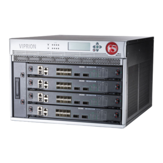
The VIPRION chassis is the housing unit that contains all of the components necessary for the VIPRION platform to operate effectively. One of the most powerful features of the VIPRION platform is that you can add, remove, or change any or all of the essential components of the platform. - Page 13 About blades A blade is the primary component that handles the traffic management within the VIPRION platform. You can install up to four blades in a VIPRION chassis. These blades comprise a group, called a cluster. The chassis includes blanks in the slots where blades are not installed. Blanks must be installed in all unused slots, as they help ensure proper airflow within the chassis and EMC compliance of the unit.
-
Page 14: Getting Started With The Viprion Platform
Chapter 1 Getting started with the VIPRION platform There are several basic tasks you must complete to get the VIPRION platform installed and set up: • Review the hardware requirements. For more information about the hardware requirements, read the following sections, Components provided with the VIPRION platform, following, and Peripheral hardware that you provide, on page 1-5. -
Page 15: Peripheral Hardware That You Provide
The VIPRION Platform Peripheral hardware that you provide For each VIPRION blade in the system, you may need to provide additional peripheral hardware. ◆ You need standard input/output hardware if you plan to use direct administrative access to the VIPRION platform. This requires a serial terminal and a null modem cable. -
Page 16: Technical Support Resources
• Release notes for the product, current and past • Updates for guides (in PDF form) • Technical notes • Answers to frequently asked questions • The Ask F5 Knowledge Base To access this site, you need to register at https://support.f5.com. 1 - 6... -
Page 17: Viprion Platform Installation
VIPRION Platform Installation • About VIPRION platform installation • PB100 and PB200 blade compatibility... -
Page 19: About Viprion Platform Installation
This ensures that the weight of the unit remains manageable as you install the unit into a rack. WARNING At least two people are required to install the VIPRION platform into a rack. General recommendations for installing a chassis in a rack... -
Page 20: Pb100 And Pb200 Blade Compatibility
Chapter 2 PB100 and PB200 blade compatibility You can use both PB100 and the newer PB200 blades in a VIPRION system that is running BIG-IP version 10.1 or later. Blade performance in mixed clusters If you choose to create a mixed cluster, a system that includes both blade types, any PB200 blades will perform at the same level as the PB100 blades. -
Page 21: Trunk Configuration In Mixed Clusters
VIPRION Platform Installation PB100 blades in a cluster running BIG-IP version 10.1 and later If you install a PB100 blade into a chassis with PB200 blades running version v10.1 or later, you could experience the following scenarios: The PB100 blade upgrades to the new software and runs (this is the ◆... - Page 22 Chapter 2 2 - 4...
-
Page 23: Viprion Lcd Panel
VIPRION LCD Panel • About the LCD panel • Using LCD panel functionality • About the LCD menus • About cluster management... -
Page 25: About The Lcd Panel
VIPRION LCD Panel About the LCD panel ® Using the LCD panel, you can control the VIPRION platform without attaching a serial or network cable. The LCD panel provides menus with options that enable you to configure certain features on the system. The following menus are available on the LCD panel. -
Page 26: Using Lcd Panel Functionality
Chapter 3 Using LCD panel functionality You can configure the LCD panel to meet your needs. Pausing on a screen Normally, the screens cycle on the LCD panel at a constant rate. However, you can push the Check button to toggle the LCD panel between Hold and Rotate modes. -
Page 27: About The Lcd Menus
VIPRION LCD Panel About the LCD menus To use the LCD menus, you must first put the LCD panel in Menu mode. To put the LCD panel in Menu mode, press the X button. After you put the LCD panel in Menu mode, use the Left Arrow, Right Arrow, Up Arrow, and Down Arrow buttons to select menu options. -
Page 28: System Menu
Chapter 3 System menu The System menu provides options for configuring the management interface on both clusters and blades. This menu also provides various options for the hardware. Option Description Suboptions Chassis Config Changes the baud rate of Serial Speed the serial port. -
Page 29: Screens Menu
VIPRION LCD Panel Screens menu The Screens menu provides options for viewing information about the system.You can use the Check button to place a check mark next to the name of the screens you would like to display when the screens cycle. -
Page 30: About Cluster Management
Chapter 3 About cluster management The LCD panel in the VIPRION platform enables you to manage clusters and blades. You can find the options for cluster and blade management in the Cluster menu item under the System menu. Configuring clusters through the LCD menu... - Page 31 VIPRION LCD Panel To configure the cluster IP subnet mask 1. Press the X button to access the LCD panel menus. 2. Use the arrow keys to select the System menu and press the Check button. 3. Use the arrow keys to select Cluster and press the Check button.
-
Page 32: Configuring Cluster Members
Chapter 3 Configuring cluster members Through the LCD panel, you have the option of configuring the management IP address of each blade within a cluster. Important When you configure an IP address for a blade, that IP address corresponds to the slot in which the blade resides. If you replace that blade with another, the new blade automatically receives the previously-configured management IP address. -
Page 33: Viprion Leds And Interfaces
VIPRION LEDs and Interfaces • About LED behavior • About platform interfaces... -
Page 35: About Led Behavior
VIPRION LEDs and Interfaces About LED behavior ® The VIPRION platform has LED displays in two locations: on the LCD panel and on the individual blades. On the LCD panel, the LEDs provide information about platform power, blade alarms, and status. -
Page 36: Indicator Led Actions
System State Alarm LED Status LED Power is off off/none off/none Active mode off/none green solid Table 4.4 Standard operating states of the LEDs on the VIPRION chassis Blade State Alarm LED Status LED Power is off off/none off/none Secondary off/none... -
Page 37: Alert Conditions Indicated By The Alarm Led
VIPRION LEDs and Interfaces Alert conditions indicated by the alarm LED When there is an alert condition on the platform, the alarm LED behaves in a specific manner. System Situation Alarm LED behavior Emergency The LED blinks red. Alert or Critical The LED is lit red. -
Page 38: Specific Status Indicated By The Leds
Chapter 4 alert BIGIP_MCPD_MCPDERR_POOL_MEMBER_MON_DOWN "Pool member (.*?):(.*?) monitor status down." snmptrap OID=".1.3.6.1.4.1.3375.2.4.0.10"; lcdwarn description="Node down" priority="1" alert BIGIP_MCPD_MCPDERR_NODE_ADDRESS_MON_DOWN "Node (.*?) monitor status down." snmptrap OID=".1.3.6.1.4.1.3375.2.4.0.12"; lcdwarn description="Node address down" priority="1" alert BIGIP_MCPD_MCPDERR_POOL_MEMBER_MON_UP "Pool member (.*?):(.*?) monitor status up." snmptrap OID=".1.3.6.1.4.1.3375.2.4.0.11" alert BIGIP_MCPD_MCPDERR_NODE_ADDRESS_MON_UP "Node (.*?) monitor status up."... -
Page 39: About Platform Interfaces
10/100/1000Mbit speeds with an F5-branded copper SFP module. • The XFP connectors can each support 10G speed with an F5-branded copper XFP module optic module installed. • The SFP+ connectors can each support 10G speed with a F5-branded optic SFP+ module or 1000 Mbit speed with a F5-branded optic SFP 1GbE module optic module installed. -
Page 40: Specifying Media Type
Chapter 4 INTERFACE Speed Pkts Pkts Drop Coll Bits Bits Errs Trunk Mbps 1/1.1 MS 10000 FD 1/1.2 MS 10000 FD 1/2.1 1000 FD 1/2.2 1000 FD 1/2.3 1000 FD 1/2.4 1000 FD 1/2.5 1000 FD 1/2.6 1000 FD 1/2.7 1000 FD 1/2.8 1000 FD... - Page 41 All interfaces on the VIPRION system default to auto-negotiate speed and duplex settings. We recommend that you configure any network equipment that you plan to use with the VIPRION system to auto-negotiate speed and duplex settings. If you connect the platform to network devices with forced speed and duplex settings, you must also force the speed and duplex settings of the platform to match the settings of the other network device.
-
Page 42: Network Interface Led Behavior
Chapter 4 Network interface LED behavior The appearance and behavior of the network interface LEDs on the performance blades indicate network traffic activity, interface speed, and interface duplexity. Table 4.8 defines the behavior for RJ45 copper interfaces. Speed LED Activity LED Link Blade type Not lit... - Page 43 VIPRION LEDs and Interfaces Table 4.10 defines the behavior for XFP optic interfaces. Speed LED Activity LED Link Blade type Not lit Not lit No link PB100 Solid green Green (with traffic) 10Gbps, full duplex PB100 Table 4.10 XFP optic interface LEDs Table 4.11 defines the behavior for SFP+ optic interfaces.
- Page 44 Chapter 4 4 - 10...
-
Page 45: Viprion Platform Maintenance
VIPRION Platform Maintenance • About maintaining the VIPRION platform • Changing blades • Changing the fan tray • Changing a power supply • Removing and replacing the LCD component... -
Page 47: About Maintaining The Viprion Platform
• LCD component replacement Changing blades The VIPRION chassis supports up to four blades. When you initially receive the platform, the slots that can contain these blades are filled with blanks, which are designed to protect the unit from dust and other particles when a slot is not in use. - Page 48 Chapter 5 Figure 5.1 A compression screw in the green (locked) position Figure 5.2 A compression screw in the red (unlocked) position 3. Grasp the two eject levers on the front of the blank and pull towards you as shown in Figure 5.3. You can now remove the blank from the slot, and add the new blade.
- Page 49 VIPRION Platform Maintenance To install a blade 1. Extend the eject levers, located on each side of the blade, into the open position. 2. Carefully lift the blade and align the guide grooves on either side with the corresponding grooves on the interior of the slot as shown in Figure 5.4.
- Page 50 Chapter 5 Figure 5.5 Locking the blade into position 5. Turn the compression screws clockwise until they are completely secured to the platform in the green (locked) position, as shown in Figure 5.1, on page 5-2. Note: The locking indicator on the compression screws turns green before the screws are completely secured to the platform;...
-
Page 51: Changing The Fan Tray
VIPRION Platform Maintenance Changing the fan tray The VIPRION platform has a removable fan tray that is designed to maintain the airflow throughout the chassis. The fans in the fan tray run constantly while the system is on. Over time, the fans can wear out, requiring you to replace the fan tray. -
Page 52: Changing A Power Supply
Chapter 5 Changing a power supply The VIPRION platform can contain up to four power supplies. These power supplies can operate in one of two modes: 120V and 220V, depending on the power source to which the power supplies are connected. -
Page 53: Replacing A Power Supply
VIPRION Platform Maintenance Replacing a power supply The design of the VIPRION platform is such that you can remove a power supply from the chassis without powering down the system, provided that there are still enough power supplies to equal one less than the number of running blades. -
Page 54: Removing And Replacing The Lcd Component
Chapter 5 Removing and replacing the LCD component The LCD component enables you to access several functions associated with the platform, such as configuring the management port for the system. To replace the LCD component 1. To remove the original LCD component, grasp the LCD component on either side, using the indentations provided. - Page 55 VIPRION Platform Maintenance 4. Press the LCD component onto the corresponding connections at the front of the platform until it clicks into place as shown in Figure 5.7. Figure 5.7 Pressing the LCD component into position ® Platform Guide: VIPRION...
- Page 56 Chapter 5 5 - 10...
-
Page 57: Guidelines For Dc Power In The Viprion Platform
Guidelines for DC Power in the VIPRION Platform • About the DC power supply option for the VIPRION platform • VIPRION DC power supply specifications... -
Page 59: About The Dc Power Supply Option For The Viprion Platform
Important You must use copper wire for the ground wire and all lead wires. Important The VIPRION platform must be installed in a restricted access location such as a central office or customer premises environment. Important You should coat bare conductors with an appropriate antioxidant compound before you make crimp connections. -
Page 60: Additional Equipment For Dc Power
Note The VIPRION platform must be grounded to a common bonding network (CBN). Important All copper grounding cable compression-type terminal lugs used for grounding must meet all appropriate UL standards. - Page 61 2. Use the Molex crimping tool to crimp the ground wire to the two-ring grounding terminal lug. F5 Networks recommends using a 2 AWG copper wire for grounding. 3. Attach the two-ring ground terminal lug (Figure 6.1) to the ground terminal.
-
Page 62: Connecting The Dc Power Source To The System
• Use the group of leads on the left rear of the chassis labeled PWR 4 and PWR 3 for power supplies 4 and 3. Figure 6.2 The terminal block plug Note The battery return terminals on the VIPRION system are in an isolated DC return (DC-I) configuration. 6 - 4... - Page 63 Guidelines for DC Power in the VIPRION Platform To connect DC power to the platform 1. After you are sure the power is off, and the ground lug is connected to the ground terminal, you can connect the DC power source.
-
Page 64: Viprion Dc Power Supply Specifications
Chapter 6 VIPRION DC power supply specifications The following specifications apply to only the VIPRION DC-powered chassis. Item Specification Power supply 1200W maximum output Rated input voltage -36 to -72 VDC Input current 10 to 40A maximum per supply Table 6.1 The VIPRION DC power supply specification Important Specifications are subject to change without notification. -
Page 65: System Power Consumption
Guidelines for DC Power in the VIPRION Platform System power consumption The actual amount of power draw from the DC power source depends on the type and number of blades and the redundancy configuration. Table 6.3 shows several possible configurations and their typical and maximum power draw. - Page 66 Chapter 6 6 - 8...
-
Page 67: Platform Airflow
Platform Airflow • Platform airflow information... -
Page 69: Platform Airflow Information
Platform Airflow Platform airflow information When you install the VIPRION platform into a rack, it is important to understand the unit’s airflow direction so that you can ensure proper cooling. Airflow for VIPRION platforms The VIPRION platforms employ a negative pressure fan system, which draws cold air in from the right and front sides of the chassis and exhausts hot air out the left and back sides of the chassis. - Page 70 Chapter 7 7 - 2...
-
Page 71: Environmental Guidelines For The Viprion Platform
Environmental Guidelines for the VIPRION Platform • Environmental requirements... -
Page 73: Environmental Requirements
® Before you install the VIPRION platform, review the following guidelines to make sure that you are installing and using the VIPRION platform in the appropriate environment. General environmental guidelines A VIPRION platform is an industrial network appliance, designed to be mounted in a standard 19-inch rack. -
Page 74: Guidelines For Ac-Powered Equipment
Chapter 8 Guidelines for AC-powered equipment An AC-powered installation must meet the following requirements: • Install the unit using a 20 Amp external branch circuit protection device per power feed. • Normally, one power feed is used for each individual power supply. Guidelines for DC-powered equipment A DC-powered installation must meet the following requirements: •... -
Page 75: Platform Specifications
Platform Specifications • General specifications for system features • AC power requirements • PB100 blade specifications • PB200 blade specifications • J100 chassis specifications • Acoustic, airflow, and altitude specifications... -
Page 77: General Specifications For System Features
Platform Specifications General specifications for system features ® The following table contains general specifications about the VIPRION platform. Item Specification Server/Node Operating ® Load balancing of any TCP/IP OS, including Windows System Compatibility NT, Windows 95, all UNIX platforms, and Mac/OS Internet/Intranet All TCP services, UDP, SIP, and SSL;... -
Page 78: Ac Power Requirements
Chapter 9 AC power requirements Before you get started with the VIPRION platform, it is important to understand the power options and requirements. This section describes AC power supply support and cable requirements. Power cables The power cable supplied with the hardware is a 220V high line input cable. -
Page 79: System Power Consumption
4 x PB100 1625W 2025W 1 x PB200 700W 925W 2 x PB200 1025W 1325W 3 x PB200 1400W 1725W 4 x PB200 1725W 2125W Table 9.4 AC mains total system power draw (high-line input) ® Platform Guide: VIPRION 9 - 3... -
Page 80: Pb100 Blade Specifications
Chapter 9 PB100 blade specifications The following specifications apply to the PB100 blade only. WARNING This platform supports only optics modules provided by F5 Networks. Item Specification Dimensions Proprietary to fit F5 Networks chassis Weight 14.5 lbs (6.58 kg) Processors Two Dual-Core AMD Opteron™... -
Page 81: Pb200 Blade Specifications
Platform Specifications PB200 blade specifications The following specifications apply to the PB200 blade only. WARNING This platform supports only optics modules provided by F5 Networks. Item Specification Dimensions Proprietary to fit F5 Networks chassis Weight 14.5 lbs (6.58 kg) Processors Two Quad-Core AMD Opteron™... -
Page 82: J100 Chassis Specifications
Chapter 9 J100 chassis specifications The following specifications apply to the J100 chassis only. WARNING This platform supports only optics modules provided by F5 Networks. Item Specification Dimensions 12.2 in. H x 17.4 in. W x 21 in. D (30.9 cm H x 44.2 W x 53.3 cm D) rack-mount chassis... -
Page 83: Acoustic, Airflow, And Altitude Specifications
Platform Specifications Acoustic, airflow, and altitude specifications To maintain the VIPRION platform, you must be familiar with additional specifications such as acoustic levels, airflow movement, and operational altitude for the VIPRION platform. Chassis with line Specification type Detail Units card... - Page 84 Chapter 9 9 - 8...
-
Page 85: Platform-Specific Hazardous Substance Levels For China
Platform-Specific Hazardous Substance Levels for China • VIPRION chassis • VIPRION blades... -
Page 87: Viprion Chassis
Platform-Specific Hazardous Substance Levels for China VIPRION chassis This table lists hazardous substances controlled by China, and shows how ® ® the F5 Networks VIPRION platform conforms to the standards. ® Platform Guide: VIPRION A - 1... -
Page 88: Viprion Blades
Appendix A VIPRION blades This table lists hazardous substances controlled by China and shows how the F5 Networks VIPRION PB100 and PB200 blades conform to the standards. A - 2... -
Page 89: Glossary
Glossary... - Page 91 A cluster is a group of slots on the VIPRION system chassis. When you insert blades into the slots of a cluster, the blades function as a single system to process application traffic.
- Page 92 Hot-swappable refers to your ability to remove a component without first shutting down the system. The VIPRION platform consists of several components: blades, LCD component, power supplies, and the fan tray, that you can replace without affecting system performance.
-
Page 93: Index
Index... - Page 95 8-1 management 3-6 for AC-powered equipment 8-2 mixed 2-2 for DC-powered equipment 8-2 common bonding network 6-2 providing peripheral 1-5 components provided with VIPRION platform 1-4 hardware installation compression screws in rack 2-1 securing 5-4 planning 2-1 unsecuring 5-1 ®...
- Page 96 4-1 for PB100 blade 9-4 for network interfaces 4-8 for PB200 blade 9-5 for power supply 4-1 for VIPRION DC-powered chassis 6-6 LED indicators hazardous substance restrictions when green 4-4 for China A-1, A-2 when yellow 4-4...
- Page 97 1-5 system airflow See airflow. system installation 2-1 System menu 3-1, 3-4 system power consumption 6-7 system power consumption, AC 9-3 technical documentation, finding 1-6 technical support web site 1-6 terminal lug 6-2 ® Platform Guide: VIPRION Index - 3...
Need help?
Do you have a question about the viprion and is the answer not in the manual?
Questions and answers