
Related Manuals for 2N SIP Speaker


Summary of Contents for 2N SIP Speaker
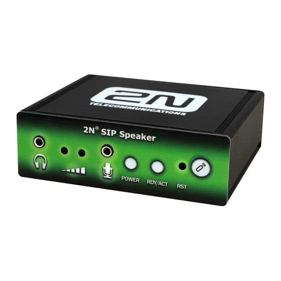
- Page 1 ® SIP Speaker Public Address Paging Configuration Manual Version 1.15.1 www.2n.cz Firmware 1.15.x...
- Page 2 1999/5/EC directive. For the full wording of the Declaration of Conformity see the CD-ROM enclosed and at www.2n.cz. The 2N TELEKOMUNIKACE Company is a holder of the ISO 9001:2008 certificate. All...
-
Page 3: Table Of Contents
Symbols Used in Manual ....................11 Future Functions and Features ..................11 2. Description and Installation ..........12 Product Description ..................... 13 2N® SIP Speaker Front and Back Panels ..............14 Before You Start ......................15 Product Completeness Check ..................15 Installation Conditions ....................15 Mounting ........................ - Page 4 Network Trace ........................ 56 Licence ........................... 56 4. Function and Use ............. 58 Basic Functions ......................59 ® SIP Speaker Button Control ..................59 ® SIP Speaker Remote Control .................. 59 ® SIP Speaker Status Signalling ................60 Operational Status Signalling ..................60 5.
-
Page 5: Product Overview
Product Overview ® In this section, we introduce the 2N SIP Speaker product, outline its application options and highlight the advantages following from its use. The section also includes safety precautions. Here is what you can find in this section: Product Description ... -
Page 6: Product Description
(to another worksite, recording machine or mobile phone) and call transfer (from the secretary to the required person, e.g.). ® SIP Speaker is equipped with a switch for you to control the electric door lock from any telephone (by tone-entering the password). ®... -
Page 7: Basic Features
Infrared remote control Optional Accessories 12V DC/2A Supply Adapter ® Universal power supply adapter for 2N SIP Speaker. With it, you can make the best of the integrated amplifier power. 802.3af PoE Injector ® Universal PoE injector for the 2N SIP Speaker power supply. -
Page 8: Sip Speaker Components And Associated Products
2N® SIP Speaker Components and Associated Products ® 1.2 2N SIP Speaker Components and Associated Products Basic Unit 914401E ® SIP Speaker Accessories 91378100 914102E 914103E PoE Injector 12VDC/2A Adapter Remote Controller... -
Page 9: Associated Products
2N® SIP Speaker Components and Associated Products Associated Products ® SIP Speaker with Flush Mounting Box Wall Mounting Loudspeaker for Soffit Mounting... -
Page 10: Upgrade
Upgrade 1.3 Upgrade ® The manufacturer reserves the right to modify 2N SIP Speaker in order to improve its qualities. Manual Changes in Documentation Version ® 1.0.0 The User Manual corresponds to 2N SIP Speaker FW version 1.15.0 Caution The manufacturer keeps improving the firmware according to the clients’... -
Page 11: Terms And Symbols Used
Terms and Symbols Used 1.4 Terms and Symbols Used Symbols Used in Manual Safety Warning Always abide by this information to prevent injury of persons. Warning Always abide by this information to prevent damage to the device. Caution Important information for system functionality. -
Page 12: Description And Installation
Description and Installation ® In this section, we describe the 2N SIP Speaker product and its installation. Here is what you can find in this section: Product Description Before You Start Mounting ... -
Page 13: Product Description
SIP Speaker with two buttons on the front panel or using an infrared remote controller. ® SIP Speaker is equipped with a digital input and output, which extend the converter options and may be helpful in special applications. ® Use an integrated web interface for 2N SIP Speaker configuration. -
Page 14: N® Sip Speaker Front And Back Panels
Product Description 2N® SIP Speaker Front and Back Panels Figure 2.1 ® SIP Speaker Front and Back Panel Connectors and Controls 1. 12V DC/2A power supply adapter connector 2. Alternative power supply connection terminals - 3. Alternative power supply connection terminals + 4. -
Page 15: Before You Start
User Manual and Software CD-ROM Certificate of Warranty Installation Conditions ® SIP Speaker is to be connected to the LAN. ® SIP Speaker is designed for indoor use. ® SIP Speaker may not be operated in damp environments. -
Page 16: Mounting
2.3 Mounting ® If you intend to use your 2N SIP Speaker unit in various interiors, please stick the four feet included in the delivery onto the bottom side of the device to avoid scratching of the underlying surface. Surface Mounting ®... -
Page 17: Electric Installation
Loudspeaker Connection ® SIP Speaker is equipped with a power amplifier for 1 (MONO) or 2 (STEREO) loudspeakers. The loudspeakers to be used must have the nominal impedance of 4-8Ω each. Refer to the table below for possible configurations and related maximum power outputs (sinus, THD <... -
Page 18: Headset/External Amplifier Connection
Electric Installation Headset/External Amplifier Connection ® SIP Speaker is equipped with a headset/external amplifier output. The 3.5mm jack is available on the front panel. Figure 2.4 Audio Output Connection Microphone/Line Connection ® SIP Speaker is equipped with a microphone/external supply output. The 3.5mm jack is available on the front panel. -
Page 19: Digital Input Connection
IN input to avoid irreversible damage of the equipment. LAN Connection ® SIP Speaker can be connected to a standard local area network using a LAN interface via the RJ-45 connector on the back panel. Always use CAT-5d or higher class cables for reliability reasons. -
Page 20: Power Supply Connection
Power Supply Connection ® SIP Speaker can be fed using active network elements or PoE injectors via the LAN interface. In case this option is unavailable, use a 12V DC/2A (Part No. 914102E) power supply or another power supply on condition that you keep the nominal values included in the Mechanical and Electrical Parameters subsection. -
Page 21: Sip Speaker Configuration
® SIP Speaker Configuration ® In this section, the 2N SIP Speaker configuration is described. Here is what you can find in this section: Default Reset Parameter Settings Firmware Upgrade ... -
Page 22: Default Reset
In some cases, it may be useful to reset the 2N SIP Speaker factory default values ® using the RESET button on the back panel. Do so, for example, if 2N SIP Speaker ceases to respond due to, for example, incorrect LAN settings, LAN configuration changes, forgotten password and so on. - Page 23 Default Reset Factory Default Reset with DHCP Client ON 1. Use a thin rigid tool (toothpick or paperclip) to press the RESET button on the front panel and push the - volume button at the same. Do not disconnect the device from the power supply while resetting.
-
Page 24: Configuration
Description of 2N Helios IP Network Scanner ® The purpose of this application is to find the dynamic IP address of 2N SIP Speaker in the local IP network. The application is available on the installation CD, which is part ®... -
Page 25: Login
Helios IP Network Scanner Window ® Select the 2N SIP Speaker to be configured. Click on it with the right-hand mouse button and select Browse... to open the web browser window, log in to ® SIP Speaker and start configuring as described in the Login subsection below. -
Page 26: Information
Configuration Information ® In this subsection find the basic information on the respective 2N SIP Speaker system. Figure 3.6 Basic Information Product name – the product name ® Software version – the current 2N SIP Speaker firmware version. For firmware update refer to the Firmware subsection. - Page 27 Outgoing – 2N SIP Speaker -to-VoIP phone call being set- ® Opponent – displays the SIP address called from 2N SIP Speaker. Call duration – the current call duration. Audio codec – the audio codec used for the current call.
-
Page 28: Telephone Directory
Set the telephone directory in the Basic settings –> Telephone directory menu. The telephone directory position corresponds to the button that can be connected to ® SIP Speaker. Push the button to call to up to three defined telephone numbers. Figure 3.7 Telephone Directory... -
Page 29: Scheduler
® present, 2N SIP Speaker need not set up a call to his or her telephone number but can automatically call other telephone numbers in the directory. Each user number can be assigned a scheduler – profile. A total of two profiles can be shared by the users. -
Page 30: General Settings
Configuration Figure 3.8 Scheduler Set-up General Settings Profile name Enter the scheduler profile name. This parameter is optional and helps you search the list of profiles more easily. Profile Time Schedule Set the presence of a user in a week period. A profile is active if the current time matches the set parameters. - Page 31 Configuration User Active if… Set at what user and profile status the telephone directory numbers will be called. The settings are applicable only if the time schedule is set for the given telephone number in the directory. Profile active only (user independent) A telephone directory number is called only if the profile is active.
-
Page 32: Switch
Configuration Switch This menu helps you set the opening codes and modes for switch 1 to ® SIP Speaker. Figure 3.9 Switch Settings Switch settings Switch enabled Enable or disable switch control globally. If disabled, the switch cannot be opened with any of the codes entered (including the user switch codes) or activated by a call or speed dialling button. - Page 33 Configuration Switch-on duration Set the switch-on time in the mono-stable mode. The time interval set here is not applied to the bi-stable mode. Sound signalling Set the sound signalling type during switch-on status. Select one of the following: Short tone, Long tone (during the whole switch-on time), or a User sound, refer to Subs.
-
Page 34: Network
2N SIP Speaker restart. By default, obtaining the IP address from the DHCP server is switched off in ® SIP Speaker (DHCP client disabled). To find the IP address of your ® ® SIP Speaker, use the 2N... -
Page 35: Date And Time
SIP Speaker is operated in a LAN and assigned no public IP address. External IP address ® Set the public IP address for your router to which 2N SIP Speaker is connected. ® If 2N SIP Speaker’s IP address is public, leave this field blank. - Page 36 ® If 2N SIP Speaker is installed in a location not included in the Time zone parameter, specify the time shift offset and daylight saving time switch on/off manually here. Remember to set the Time zone to the Use TZ rule below function.
-
Page 37: Sip Settings
User Settings Display name Set the name to be displayed to the called party. The name will also be displayed ® in the right-hand upper corner of the web interface and used for 2N SIP Speaker ® identification in the 2N Helios IP Network Scanner application. -
Page 38: Other Settings
Enter the password to be used for authorisation during registration and calling. Other Settings Local SIP port ® Set the communication port to be used for SIP signalling by 2N SIP Speaker. The ® change of this parameter will not show until the next 2N SIP Speaker restart. -
Page 39: Administration Web Server
Web server You can disable the administration web server launching. The change of this ® parameter will not show until the next 2N SIP Speaker restart. To enable the web server, follow the instructions mentioned in the Factory Default Reset subsection. -
Page 40: Audio
SIP Speaker configuration through the administration web server. Enter the new password into both of the Admin password and Confirm password fields. Audio ® This menu is used for the 2N SIP Speaker audio settings. Figure 3.14 Audio Parameter Settings Speaker Settings Master volume Set the global loudspeaker volume. - Page 41 Configuration Warning volume ® Set the volume of the 2N SIP Speaker signal tones that announce status changes. Key beep volume Set the volume of the tone generated whenever a key is pushed. Switch open volume Set the volume of the unlocking signalling tone.
-
Page 42: Audio Codecs
® Set the audio codecs for 2N SIP Speaker telephone call set-ups. Select G.711 (PCMA or PCMU), L16, or G.729. Audio codec priorities are determined by the sequence: the first codec in the sequence has the highest priority. Codec G.729 is available with a licence key only. -
Page 43: Streaming
This menu allows the user to enable audio streaming into your LAN without affecting ® the other functions of 2N SIP Speaker. This function may be used for security purposes. An RTSP supporting receiver is required for acceptance of audio streaming. - Page 44 Set whether the audio channel is part of the stream transmitted. Caution ® SIP Speaker enables to send a single stream at a time. When a stream request comes from another IP address, the current stream is discontinued and the stream is distributed to the IP address that sent the request.
- Page 45 In the main menu select the source for playing the audio, Media->Open Network In the network card select the RTSP protocol and insert the IP address of the ® SIP Speaker device that is sending the audio streaming (rtsp://192.168.22.67 in this case). Figure 3.18 RTSP Stream IP Address Setting...
-
Page 46: Auto Update
After the confirmation button OK is pushed, the audio player window will appear. Figure 3.19 Streaming Audio Receiving Auto Update ® SIP Speaker allows both for manual and automatic updates of configuration and firmware. The automatic update is done through a TFTP server. Figure 3.20 Auto Update Settings... -
Page 47: System Log
Update time Set a period for automatic firmware downloading attempts from the TFTP server. ® SIP Speaker periodically (at a predefined time once a day) checks the TFTP ® server for a later firmware version. Having found one, 2N SIP Speaker updates the firmware and restarts automatically. -
Page 48: Miscellaneous
Set the level of detail of the reports. Syslog server The IP address of the server on which the system log application is running. Miscellaneous ® Here set the additional parameters of 2N SIP Speaker that were not included in the above-described menus. - Page 49 Set the maximum call duration. When the call end is approaching, ® SIP Speaker starts generating tones signalling the end of the call. The call will automatically be terminated 10s after this signal. To prolong the call, send a DTMF code (push #, e.g.) on your phone.
- Page 50 Incoming Calls Automatic answer ® Defines how 2N SIP Speaker should behave when a call is coming. If the ® Automatic answer is disabled, 2N SIP Speaker signals an incoming calls by ringing and the external subscriber can answer or reject the call by pushing * or # ®...
-
Page 51: Tools
(1) and Y is 0 for switch off, 1 for switch on and 2 for change over. Tools ® This menu helps you set the 2N SIP Speaker date and time manually and reboot the device. Figure 3.23 Tools... -
Page 52: Configuration
Date and Time subsection). Push the button to synchronise the ® SIP Speaker time with your PC time. Reboot device Used for device restarting in case of changes of some configuration parameters, namely network settings, administration web interface settings and some SIP configuration parameters. -
Page 53: Firmware
Manual Firmware Update Used for manual firmware updating using the configuration web interface. Use the Browse button to select the new firmware file and push to upload it to ® SIP Speaker. For automatic update refer to the Auto Update subsection. -
Page 54: User Sounds
Configuration Figure 3.25 Firmware User Sounds ® This menu helps create customised signalling of 2N SIP Speaker states by replacing the default tone signalling with user sound files. User Sound Upload ® Used for handling user sound files within 2N SIP Speaker. - Page 55 Configuration Figure 3.26 User sounds The following user sounds can be used: Hang-up by remote party – here replace the disconnect tone signalling that the called station has hung up. Busy tone – replace the standard busy tone. Invalid input – replace the invalid switch password sound. Invalid position –...
-
Page 56: Network Trace
Figure 3.27 Network trace Licence This menu is used for entering licence keys. Licence keys upgrade the ® SIP Speaker functionality. Contact your local distributor for the licence key to ® your 2N SIP Speaker. - Page 57 Licence expiry ® SIP Speaker are available with the Basic licence. You can activate the Professional licence for a limited operating time (800 hours) to test all the system capacities. Click on the Start evaluation mode for 800 hours to enable the Professional licence.
-
Page 58: Function And Use
Configuration Function and ® This section provides the basic and extended functions of the 2N SIP Speaker product. Here is what you can find in this section: ® SIP Speaker Button Control ® SIP Speaker Remote Control ®... -
Page 59: Basic Functions
Basic Functions 4.1 Basic Functions ® SIP Speaker Button Control ® SIP Speaker is equipped with two buttons on the front panel. Figure 4.1 Volume Buttons ® Use these buttons to adjust the 2N SIP Speaker volume. ® SIP Speaker Remote Control ®... -
Page 60: Sip Speaker Status Signalling
Basic Functions ® SIP Speaker Status Signalling ® SIP Speaker is equipped with colour LEDs on the front panel, which indicate operational statuses. Figure 4.3 Status LEDs Refer to the table below for the list of available operational statuses: POWER Status Device powered off. - Page 61 SIP Speaker. Invalid telephone number or invalid switch activation code. ® SIP Speaker allows you to store an extension number or enter the switch opening code. If the number/code is invalid, this tone combination is used. Default reset of network parameters.
- Page 62 Basic Functions Connected call when calling from a telephone to ® SIP Speaker. ® When calling from your VoIP telephone to 2N SIP Speaker, you get a short call connection tone. Table 4.2 List of Tone Signals...
-
Page 63: Technical Parameters
Technical Parameters ® This section describes the technical parameters of the 2N SIP Speaker product. -
Page 64: Technical Parameters
Technical Parameters 5.1 Technical Parameters Mechanical and Electrical Parameters Parameter Value Dimensions 105 x 34 x 86 mm Dimensions (incl. L-profiles) 130 x 34 x 86 mm Weight 300 g External power supply 12V DC / 1.8A LAN supply PoE IEEE 802.3af Status signalling 3 RG LEDs on front panel Local control... - Page 65 Technical Parameters Parameter Value Digital output 24V 1A AC/DC relay output, galvanically isolated Digital input 5 to 24V DC digital input, galvanically isolated Audiocodecs G.711 (PCMA, PCMU), G.729 (Annex A, B),...
-
Page 67: Supplementary Information
Supplementary Information ® This section provides supplementary information on the 2N SIP Speaker product. Here is what you can find in this section: Applicable Directives, Laws and Regulations List of Figures Troubleshooting List of Abbreviations ... -
Page 68: List Of Abbreviations
List of Abbreviations 6.1 List of Abbreviations FW (Firmware) Software responsible for system function. HW (Hardware) For this purpose, hardware means an electronic device, circuit, board, component, etc.. LAN (Local Area Network) PC (Personal Computer) IBM PC compatible personal computer. SW (Software) ... -
Page 69: List Of Figures
List of Figures 6.2 List of Figures ® Figure 2.1 SIP Speaker Front and Back Panel............... 14 Figure 2.2 Mounting Holes ......................16 Figure 2.3 Loudspeaker Connection ....................17 Figure 2.4 Audio Output Connection ....................18 Figure 2.5 Audio Input Connection ....................18 Figure 2.6 Digital Output Connection .................... - Page 70 List of Figures Figure 3.18 RTSP Stream IP Address Setting ................45 Figure 3.19 Streaming Audio Receiving ..................46 Figure 3.20 Auto Update Settings ....................46 Figure 3.21 System Log ........................48 Figure 3.22 Miscellaneous Settings ....................49 Figure 3.23 Tools ..........................51 Figure 3.24 Configuration Setting ....................
-
Page 71: List Of Tables
List of Tables 6.3 List of Tables Table 4.1 List of Statuses......................60 Table 4.2 List of Tone Signals ...................... 62... - Page 72 2N TELEKOMUNIKACE a.s. Modřanská 621, 143 01 Prague 4, Czech Republic Tel.: +420 261 301 111, Fax: +420 261 301 999 E-mail: obchod@2n.cz Web: www.2n.cz...
Need help?
Do you have a question about the SIP Speaker and is the answer not in the manual?
Questions and answers