Advertisement
Quick Links
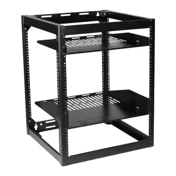
CFR1615/ CFR1620
Instruction Manual
We are here to help!
Please contact Customer Service with any questions.
sanus.com
Customer Service
Americas: 800-359-5520 • 952-225-6013 • info@sanus.com
Europe, Middle East, and Africa: +31 (0) 495 580 852 • europe.sanus@milestone.com
Asia Pacifi c: 86 755 8996 9226 • sanus.ap@milestone.com
SANUS • 6436 City West Parkway • Eden Prairie, MN 55344 USA
©2013 Milestone AV Technologies, a Duchossois Group Company. All rights reserved. Sanus is a division of Milestone.
All other brand names or marks are used for identifi cation purposes and are trademarks of their respective owners.
Advertisement

Related Manuals for Sanus CFR1615


Summary of Contents for Sanus CFR1615
- Page 1 SANUS • 6436 City West Parkway • Eden Prairie, MN 55344 USA ©2013 Milestone AV Technologies, a Duchossois Group Company. All rights reserved. Sanus is a division of Milestone. All other brand names or marks are used for identifi cation purposes and are trademarks of their respective owners.
-
Page 2: Specifications
English IMPORTANT SAFETY INSTRUCTIONS – SAVE THESE INSTRUCTIONS – PLEASE READ ENTIRE MANUAL PRIOR TO USE Specifications Weight capacity free standing or stacked-DO NOT EXCEED: 272 kg (600 lb.) includes any components or accessories Weight capacity wall mounted-DO NOT EXCEED: 90.7 kg (200 lb.) includes any components or accessories ... - Page 3 Technical Specifications CFR1615 20.4 in. 20.24 in. 518.41 mm 514.06 mm 15.12 in. 384.05 mm 19.0 in. 482.60 mm 1.75 in. 44.40 mm 18.0 in. 457.25 mm 26.26 in. 28.58 in. 667.03 mm 725.98 mm 3.49 in. 88.85 mm...
- Page 4 Technical Specifications CFR1620 20.4 in. 20.24 in. 518.41 mm 514.06 mm 18.0 in. 457.25 mm 19.0 in. 482.60 mm 35.00 in. 37.33 in. 3.49 in. 889.0 mm 948.2 mm 88.85 mm 15.12 in. 384.05 mm 1.75 in. 44.40 mm...
-
Page 5: Supplied Parts
Supplied Parts WARNING: This product contains small items that could be a choking hazard if swallowed. Before starting assembly, verify all parts are included and undamaged. If any parts are missing or damaged, do not return the damaged item to your dealer;... - Page 6 Supplied Parts 1/4-20 x 3/8 in. 1/4-20 [09] x 25 [10] x 4 [08] x 12 [15] x 4 [12] x 2 [11] x 2 [13] x 4 [16] x 2 5/16 x 3½ in. [07] x 4 [14] x 4...
-
Page 7: Frame Construction
Frame Construction Fit brace [03] over left frame [01] Slide brace [03] back over vertical horizontal screw stud. screw studs. [01] [01] [03] [03] Attach right frame [02] to lower brace [03] Secure brace [03] with nuts [08]. [08] with nuts [08]. [08] [03] 13mm... - Page 8 Frame Construction Repeat steps 1 and 2 with upper Attach alignment panels [04] with brace [03]. screws [09]. [03] [04] [09] [02] [01] Secure upper brace [03] with nuts [08]. 13mm (1/2 in. [08] [03] [04] [01] [02] [09]...
- Page 9 Install Feet (optional) for use on floor Lay assembled frame on its back. Install feet [07]. [07] Tighten nuts (N) until they are fl ush with the Adjust the feet [07] to level the rack. bottom of the rack. CAUTION: To avoid potential injury or property damage, always ensure that your rack is level.
- Page 10 Install Casters (optional CA6CK caster kit purchased separately) Install casters (purchased separately). Make sure casters are screwed in until the nuts at the top of the casters are fl ush against the frame. Lay assembled frame on its back.
- Page 11 Stacking (second rack sold separately) Fit second frame (without feet) onto Secure frames with stacking screws fi rst frame. [10]. [10]...
- Page 12 Single Wall Mounting (wood stud) Locate studs. Verify the center of the stud with an Level frame assembly and mark hole locations. awl or thin nail or use an edge to edge stud fi nder. CAUTION: Avoid potential personal injuries and property damage! ...
- Page 13 Start upper lag bolts [14], hang frame assembly Drill pilot holes as illustrated. on bolts [14], then slip "U" washers [11] onto CAUTION: Improper use could reduce the the upper bolts [14]. Lower bolts [14] use round holding power of the lag bolt. To avoid potential washers [12].
- Page 14 Single Wall Mounting (solid concrete and concrete block) Drill pilot holes as illustrated. Level frame assembly and mark hole locations. CAUTION: To avoid potential injuries or property damage: Pilot holes MUST be drilled to a depth of 89 mm (3½...
- Page 15 Start upper lag bolts [14], hang frame assembly Insert lag bolt anchors [13]. on bolts [14], then slip "U" washers [11] onto the upper bolts [14]. Lower bolts [14] use round CAUTION: To avoid potential injuries or washers [12]. property damage be sure the anchors [13] seat 13mm Tighten lag bolts [14] only until the washers [12] fl ush with the concrete surface.
- Page 16 Wall Mounting - Stacking (wood stud) Fit second frame onto fi rst frame. Locate studs. Verify the center of the stud with an Secure frames with stacking screws awl or thin nail or use an edge to edge stud fi nder. [10].
- Page 17 Drill pilot holes as illustrated. Level frame assembly and mark top hole locations. CAUTION: Improper use could reduce the holding power of the lag bolt. To avoid potential injuries or property damage: pilot holes MUST be drilled to a depth of 89 mm (3.5 in.), using a 5.5 mm (7/32 in.) diameter drill bit.
- Page 18 Hang frame assembly on bolts [14]. Slip "U" washers [11] onto the bolts [14]. Tighten lag bolts [14] only until the washers [11] are pulled fi rmly against the brace [03]. CAUTION: Improper use could reduce the holding power of the lag bolt. To avoid potential injuries or property damage DO NOT over- tighten the lag bolts [14].
- Page 19 Drill remaining pilot holes as illustrated. Tighten lag bolts [14] only until the washers [11] CAUTION: and [12] are pulled fi rmly against the brace [03]. Improper use could reduce the holding power of the lag bolt. To avoid potential CAUTION: Improper use could reduce the injuries or property damage: pilot holes MUST...
- Page 20 Wall Mounting - Stacking (solid concrete or concrete block) Fit second frame onto fi rst frame. Level frame assembly and mark hole locations. Secure frames with stacking screws [10]. [10]...
- Page 21 Drill pilot holes as Insert lag bolt anchors illustrated. [13]. CAUTION: To avoid CAUTION: potential injuries or avoid potential injuries property damage: or property damage Pilot holes MUST be be sure the anchors drilled to a depth of 89 [13] seat fl ush with the mm (3.5 in.) using a 10 10 mm...
- Page 22 Start upper lag bolts [14], hang frame assembly on bolts [14], then slip "U" washers [11] onto the upper bolts [14]. Lower bolts [14] use round washers [12]. [14] Tighten lag bolts [14] only until the washers [11] [11] and [12] are pulled fi rmly against the brace [03]. CAUTION: Improper use could reduce the holding power of the lag bolt.
-
Page 23: Install Shelves
Install Shelves After at least 3 shelves or rack mounted Install shelves [05] and [06] with components are installed, the alignment screws [09]. panels [04] may be relocated or removed for additional rack space. [05] [04] [06] [09] [04]... - Page 24 Install Shelf Backstops (optional) CAUTION: To prevent tipping, always load the rack from the bottom up, and load the heaviest item in the rack fi rst. 50% of the total weight should be mounted in the lower 1⁄3 of the rack. 1.
- Page 25 Install Component Straps (optional) 1. Slide straps [16] through slots in sides of shelves. 2. Wrap straps [16] over component to secure. [16] [16]...
Need help?
Do you have a question about the CFR1615 and is the answer not in the manual?
Questions and answers