Table of Contents
Advertisement
Advertisement
Table of Contents

Related Manuals for Innova 3100j


Summary of Contents for Innova 3100j
-
Page 2: Table Of Contents
VEHICLE APPLICATIONS - SRS VEHICLE APPLICATIONS – MAKES COVERED ........ VEHICLE APPLICATIONS - OIL RESET VEHICLE APPLICATIONS – MAKES COVERED ........ GLOSSARY GLOSSARY OF TERMS AND ABBREVIATIONS ........ 100 WARRANTY AND SERVICING LIMITED ONE YEAR WARRANTY ............105 SERVICE PROCEDURES ..............105 3100j... -
Page 3: Introduction
Toyota/Lexus vehicles, as well as Anti-Lock Brake System (ABS) DTCs, Supplemental Restraint System (SRS) DTCs and vehicle information. The types of enhanced data available depends on the vehicle make. To learn more about vehicle Computer Control Systems and OBD2, see COMPUTER ENGINE CONTROLS on page 15. 3100j... -
Page 4: You Can Do It
System Status is indicated by LED indicators. Easy To Define ..Read code definitions from the diagnostic tool’s LCD display. View Freeze Frame data. View Anti-Lock Brake System (ABS) DTCs. View Supplemental Restraint System (SRS) DTCs. 3100j... -
Page 5: Safety Precautions
Connecting or disconnecting test equipment when the ignition is ON can damage test equipment and the vehicle's electronic components. Turn the ignition OFF before connecting the diagnostic tool to or disconnecting the diagnostic tool from the vehicle’s Data Link Connector (DLC). 3100j... - Page 6 Don't wear loose clothing or jewelry when working on an engine. Loose clothing can become caught in the fan, pulleys, belts, etc. Jewelry is highly conductive, and can cause a severe burn if it makes contact between a power source and ground. 3100j...
-
Page 7: About The Diagnostic Tool
(300 mm) of center of the panel, on the driver’s side of most vehicles. It should be easily accessible and visible from a BEHIND kneeling position outside the NEAR ASHTRAY CENTER vehicle with the door open. OF DASH LEFT CORNER OF DASH 3100j... -
Page 8: Battery Replacement
ENTER button to confirm your selection. After the initial language and unit of measurement selections are performed, these, as well as other settings, can be changed as desired. Proceed to “ADJUSTMENTS AND SETTINGS” on page 85 for further instructions. 3100j... -
Page 9: Diagnostic Tool Controls
PCM to retrieve diagnostic data from the computer’s memory. 5. M button – When pressed while linked to a vehicle, displays the “Main Menu.” 6. FF button – When pressed while linked to a vehicle, displays Freeze Frame data for the priority DTC. 3100j... -
Page 10: Display Functions
14. CABLE - Connects the diagnostic tool to the vehicle’s Data Link Connector (DLC). DISPLAY FUNCTIONS Figure 2. Display Functions See Figure 2 for the locations of items 1 through 13, below. 1. I/M MONITOR STATUS field - Identifies the I/M Monitor status area. 3100j... - Page 11 “Freeze Frame” data has been stored. If “1” is a “Pending” code, there may or may not be “Freeze Frame” data stored in memory. 9. Code Enumerator - Indicates the total number of codes retrieved from the vehicle’s computer. 3100j...
- Page 12 2 - Repair immediately if drivability issues are present. Threat to essential system components if not repaired as soon as possible. 3 - Stop and repair vehicle immediately to prevent interrelated failures. Harmful and damaging to essential system components. 3100j...
-
Page 13: Onboard Diagnostics
By switching from mechanical to electronic engine controls, vehicle manufacturers are able to control fuel delivery and spark timing more precisely. Some newer Computer Control Systems also provide control over other vehicle functions, such as transmission, brakes, charging, body, and suspension systems. 3100j... - Page 14 EGR valve or Ignition Module to perform these actions. TYPICAL COMPUTER OUTPUT DEVICES CONTROL SYSTEM Fuel Injectors Idle Air Control EGR Valve Ignition Module On-Board Computer INPUT DEVICES Coolant Temperature Sensor INPUT DEVICES Throttle Position Sensor Oxygen Sensors Fuel Injectors 3100j...
- Page 15 The California Air Resources Board (CARB) conducted studies on OBD1 equipped vehicles. The information that was gathered from these studies showed the following: A large number of vehicles had deteriorating or degraded emissions-related components. These components were causing an increase in emissions. 3100j...
- Page 16 (scan tools, code readers, etc.) and the vehicle’s on-board computer. OBD2 Terminology The following terms and their definitions are related to OBD2 systems. Read and reference this list as needed to aid in the understanding of OBD2 systems. 3100j...
- Page 17 “Off.” Since each of the fifteen monitors is designed to run diagnostics and testing on a different part of the engine or emissions system, the “Trip Drive Cycle” needed for each individual Monitor to run and complete varies. 3100j...
-
Page 18: Diagnostic Trouble Codes (Dtcs)
The 2nd character is a numeric digit (0 thru 3). It identifies the “type” of code (Generic or Manufacturer-Specific). Generic DTCs are codes that are used by all vehicle manu- facturers. The standards for generic DTCs, as well as their definitions, are set by the Society of Automotive Engineers (SAE). 3100j... - Page 19 Auxiliary Emission Control System Vehicle Speed Control and Idle Control System Computer Output Circuits Transmission 8 - Transmission 9 - Transmission A - Hybrid Propulsion B - Hybrid Propulsion Hybrid Propulsion Identifies what section of the system is malfunctioning 3100j...
- Page 20 If the failure is not found on the second Trip, the Pending DTC is erased from the computer’s memory. The MIL will stay lit for both Type “A” and Type “B” codes until one of the following conditions occurs: 3100j...
-
Page 21: Obd2 Monitors
Continuous Monitors Three of these Monitors are designed to constantly monitor their associated components and/or systems proper operation. Continuous Monitors run constantly when the engine is running. The Continuous Monitors are: Comprehensive Component Monitor (CCM) Misfire Monitor Fuel System Monitor 3100j... - Page 22 In this case, the signal would fail the rationality test. The CCM is supported by both “spark ignition” vehicles and “compression ignition” vehicles. The CCM may be either a “One-Trip” or a “Two-Trip” Monitor, depending on the component. 3100j...
- Page 23 The computer checks the efficiency of the catalytic converter by monitoring the oxygen sensors used by the system. One sensor is located before (upstream of) the converter; the other is located after (downstream of) the converter. If the catalytic converter loses its ability to store oxygen, 3100j...
- Page 24 The fumes are stored in the charcoal canister. The computer controls the flow of fuel vapors from the charcoal canister to the engine via a purge solenoid. The computer energizes or de-energizes the purge solenoid (depending on solenoid design). The purge solenoid opens a 3100j...
- Page 25 The oxygen sensor must reach a temperature of at least 600-650°F, and the engine must reach normal operating temperature, for the computer to enter into closed-loop operation. The oxygen sensor only functions when the computer is in closed-loop. A properly operating 3100j...
- Page 26 Pending Code. The computer does not command the MIL on at this time. If the fault is sensed again on the second trip, the computer commands the MIL “On,” and saves the code in its long-term memory. 3100j...
- Page 27 Pending Code. The computer does not command the MIL on at this time. If the fault is sensed again on the second trip, the computer commands the MIL “On,” and saves the code in its long-term memory. 3100j...
- Page 28 Number of trips needed, with no faults present, to erase a Pending Number and type of trips or drive cycles needed, with no faults present, to turn off the MIL Number of warm-up periods needed to erase the DTC from the computer’s memory after the MIL is turned off 3100j...
- Page 29 Once per 3 trips trip NOx Adsorber Once per 3 trips Monitor trip Boost Pressure Once per 3 trips System Monitor trip Exhaust Gas Sensor Once per 3 trips Monitor trip PM Filter Monitor Once per 3 trips trip 3100j...
-
Page 30: Preparation For Testing
*VIN: Vehicle Identification Number, found at the base of the windshield on a metallic plate, or at the driver door latch area (consult your vehicle owner's manual for location). TRANSMISSION: Automatic Manual Please check all applicable items in each category. DESCRIBE THE PROBLEM: 3100j... - Page 31 Is too fast Fluctuates up and down RUNNING CONDITIONS No symptoms Backfires Runs rough Misfires or cuts out Lacks power Engine knocks, pings or rattles Bucks and jerks Surges Poor fuel economy Dieseling or run-on Hesitates or stumbles on accelerations 3100j...
- Page 32 Above 55° F (13° C) Below freezing (32° F / 0° C) CHECK ENGINE LIGHT / DASH WARNING LIGHT Sometimes ON Always ON Never ON PECULIAR SMELLS "Hot" Gasoline Sulfur ("rotten egg") Burning oil Burning rubber Electrical STRANGE NOISES Rattle Squeak Knock Other 3100j...
-
Page 33: Before You Begin
Check all electrical wiring and harnesses for proper connection. Make sure wire insulation is in good condition, and there are no bare wires. Make sure the engine is mechanically sound. If needed, perform a compression check, engine vacuum check, timing check (if applica- ble), etc. 3100j... -
Page 34: Vehicle Service Manuals
Motor Publications 5600 Crooks Road, Suite 200 Troy, Michigan 48098 Phone: 800-426-6867 Web: www.motor.com FACTORY SOURCES Ford, GM, Chrysler, Honda, Isuzu, Hyundai and Subaru Service Manuals Helm Inc. 14310 Hamilton Avenue Highland Park, Michigan 48203 Phone: 800-782-4356 Web: www.helminc.com 3100j... -
Page 35: Using The Diagnostic Tool
DLC connector. Check your fuse panel and replace any burned-out fuses. If replacing the fuse(s) does not correct the problem, consult your vehicle’s repair manual to identify the proper computer (PCM) fuse/circuit, and perform any necessary repairs before proceeding. 3100j... - Page 36 Vehicle Information screen displays. If the information shown is correct for the vehicle under test, use the and DOWN buttons, as necessary, to highlight Yes, then press the ENTER button. Proceed to step 10. 3100j...
- Page 37 Page to view additional options. The Select Model screen dis- plays. Use the UP and DOWN buttons, as necessary, to highlight the desired vehicle model, then press the ENTER button to continue. If necessary, select Next Page to view additional options. 3100j...
- Page 38 11. To read the display: Refer to DISPLAY FUNCTIONS on page 8 for a descrip- tion of LCD display elements. A visible icon indicates that the diagnostic tool is being powered through the vehicle’s DLC connector. 3100j...
- Page 39 SENT – If the yellow LED is illuminated, it may indicate a Pending code is present. Check diagnostic tool’s display confirmation. Pending code is confirmed by the presence of a numeric code and the word PENDING on the diagnostic tool’s LCD display. 3100j...
- Page 40 See VIEWING FREEZE FRAME DATAon page 39. 3100j...
-
Page 41: Viewing Freeze Frame Data
The Freeze Frame screen displays. Saved engine conditions include but are not limited to: engine speed, open or closed loop operation, fuel system commands, coolant tem- perature, calculated load value, fuel pressure, vehicle speed, air flow rate and intake manifold pressure. 3100j... -
Page 42: The System Menu
ENTER button to view the selected information. To view ABS DTCs: Select ABS from the System Menu. Refer to VIEWING ABS DTCs on page 52 to view ABS DTCs for your vehicle. 3100j... -
Page 43: Viewing Oem Enhanced Dtcs
Refer to the appropriate paragraph to view enhanced DTCs for your vehicle: Chrysler/Jeep Enhanced DTCs .....page 42 Ford/Mazda Enhanced DTCs ....page 43 GM/Isuzu Enhanced DTCs ....page 46 Honda/Acura Enhanced DTCs ....page 48 Toyota/Lexus Enhanced DTCs....page 50 3100j... - Page 44 Diagnostic Trouble Code (DTC), the number of the code currently being displayed and the total number of codes retrieved, and the type of code. The related code definition is shown in the lower section of the LCD display. 3100j...
- Page 45 Ford vehicles only. When Ford OEM Enhanced is chosen from the System Menu, the Ford Enhanced menu displays. You may view DTCs for either the “Continuous Memory Test”, “KOEO (Key On Engine Off) Test” or “KOER (Key On Engine Running) Test.” 3100j...
- Page 46 If the diagnostic tool cannot link to the vehicle’s computer after three attempts, the message “Contact Technical Support” displays. - Press the SYSTEM MENU button to return to the System Menu. - Turn ignition off, disconnect the diagnostic tool. - Contact Technical Support for assistance. 3100j...
- Page 47 The related code definition is shown in the lower section of the LCD display. If the definition for the currently displayed code is not available, an advisory message shows on the diagnostic tool’s display. 3100j...
- Page 48 OEM enhanced DTCs from the vehicle’s computer. 1. A “One moment please” message displays while diagnostic tool retrieves the selected DTCs. If the diagnostic tool fails to link to vehicle’s computer, “Communication Error” message shows on the diagnostic tool’s display. 3100j...
- Page 49 In the case of long code definitions, or when viewing Freeze Frame data, a small arrow is shown in the upper/lower right-hand corner of the code display area to indicate the presence of additional information. Use the UP DOWN buttons, as necessary, to view the additional information. 3100j...
- Page 50 COVERED on page 5 for vehicle compliance verification information. - Verify the connection at the DLC, and verify the ignition is ON. - Turn the ignition OFF, wait 5 seconds, then back ON to reset the computer. - Press the POWER/LINK button to continue. 3100j...
- Page 51 The diagnostic tool will display a code only if codes are present in the vehicle’s computer memory. If no codes are present, a “No OEM Enhanced DTCs presently stored in the vehicle’s computer.” is displayed. Press the button to return to the System Menu. 3100j...
- Page 52 If the diagnostic tool cannot link to the vehicle’s computer after three attempts, the message “Contact Technical Support” displays. - Press the SYSTEM MENU button to return to the System Menu. - Turn ignition off, disconnect the diagnostic tool. - Contact Technical Support for assistance. 3100j...
- Page 53 To re-establish communication, press the POWER/LINK button again. 4. When the last retrieved DTC has been displayed and the DTC button is pressed, the diagnostic tool returns to the “Priority” code. 3100j...
-
Page 54: Viewing Abs Dtcs
Global OBD2 mode. VIEWING ABS DTCs Refer to Vehicle Applications - ABS on page 97 for vehicle makes covered. For a complete list of vehicle’s covered, please visit www.innova.com. Reading ABS DTCs 1. When ABS is chosen from the System Menu, "One... - Page 55 To re-establish communication, press the POWER/LINK button again. 4. When the last retrieved DTC has been displayed and the DTC button is pressed, the diagnostic tool returns to the “Priority” code. 3100j...
-
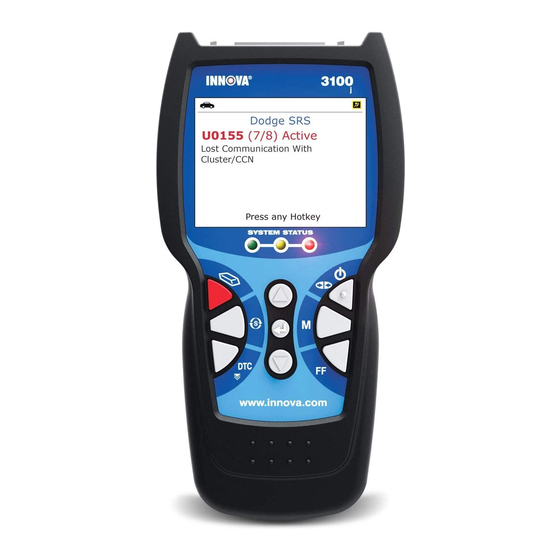
Page 56: Viewing Srs Dtcs
“Contact Technical Support” displays. - Press the SYSTEM MENU button to return to the System Menu. - Turn the ignition off, and discon- nect the diagnostic tool. - Contact Technical Support for assistance. 3100j... - Page 57 Scan Tool’s communication link with the vehicle’s computer disconnects. re-establish communication, press POWER/LINK button again. 4. When the last retrieved DTC has been displayed and the DTC button is pressed, the Scan Tool returns to the “Priority” code. 3100j...
-
Page 58: Erasing Diagnostic Trouble Codes (Dtcs)
Code Retrieval procedure for OEM enhanced DTCs as described on page 39, for ABS DTCs as described on page 52, or for SRS DTCs as described on page 54 Wait until the codes are displayed on the diagnostic tool’s LCD and then proceed to step 3. 3100j... - Page 59 If proper repairs to correct the problem that caused the code(s) to be set are not made, the code(s) will appear again (and the check engine light will illuminate) as soon as the vehicle is driven long enough for its Monitors to complete their testing. 3100j...
-
Page 60: About Repairsolutions
RepairSolutions® lets you view, save, and email the diagnostic data retrieved from a vehicle’s on-board computer(s) using an Innova diagnostic tool. At the core of RepairSolutions® is an extensive knowledge database, developed by compiling and analyzing years worth of “real world”... - Page 61 The Portal page gives you an overview of your RepairSolutions® account. It shows your Account Status and provides access to the reports you have most recently generated using a registered Innova tool. Innova Account The Innova Account section lets you manage the vehicles and tools you’ve registered with your account and manage your personal...
- Page 62 Using the Diagnostic Tool ABOUT REPAIRSOLUTIONS® Registered Devices – You can register all of your Innova tools with your RepairSolutions® account. The Registered Devices page shows all the tools registered to your account along with the date on which the device was activated.
- Page 63 Shop Locator will return a list facilities near your location based on the Zip Code you provide. Hardware Requirements: Innova Diagnostic Tool Mini USB Cable (included with tool) Minimum System Operating Requirements: Windows®...
-
Page 64: I/M Readiness Testing
Using the Diagnostic Tool I/M READINESS TESTING 2. Visit www.innova.com, download and install the latest PC-Link soft- ware for your Scan Tool. Select the Support tab, then choose Manuals and Software. Use the drop-down menu provided to select your tool Category and tool Model to download the latest PC- Link software. - Page 65 “HAVE RUN” status. This indicates that all Monitors have run and completed their diagnostic testing. The “HAVE RUN” status remains in the computer's memory, unless the Diagnostic Trouble Codes are erased or the vehicle's computer memory is cleared. 3100j...
- Page 66 Emissions Test (Smog Check), and there is a good possibility that it can be certified. 2. YELLOW LED - Determine from the CODE RETRIEVAL PROCEDURE (page 33) which of the two possible conditions is causing the yellow LED to light. 3100j...
- Page 67 A "permanent" DTC can be cleared only by the vehicle's computer following successful completion of the monitor that caused the fault to set. 3100j...
- Page 68 Follow the manufacturer's procedures to perform a Trip Drive Cycle for the appropriate Monitors. While observing the Monitor icons on the diagnostic tool’s LCD display, perform a Trip Drive Cycle for the appropriate Monitor or Monitors. 3100j...
- Page 69 If, after the Monitor has run, the MIL on the vehicle's dash lights and/or a DTC associated with that Monitor is present in the vehicle's computer, the repair was unsuccessful. Refer to the vehicle's service manual and recheck repair procedures. 3100j...
-
Page 70: Additional Functions
O2 Sensor Test - Retrieves and displays O2 sensor monitor test results from your vehicle's on-board computer. OBD Monitor Test - Retrieves and displays test results for emission-related powertrain components and systems that are not continuously monitored. EVAP Test - Performs a leak test for the vehicle's EVAP system. 3100j... - Page 71 The diagnostic tool does not perform O2 sensor tests, but retrieves results from the most recently performed O2 sensor tests from the on-board computer's memory. You may retrieve O2 sensor test results for only one test of one sensor at any given time. 3100j...
- Page 72 UP and DOWN buttons, as necessary, to highlight Back on the Select Sensor screen, then press the ENTER button to return to the System Test menu; or, press the M button to return to the Main Menu. 3100j...
- Page 73 ENTER button. 4. When test results have been retrieved, data for the selected test will show on diagnostic tool’s display. display shows the following information: Test ID number Module ID number Component ID number Min or Max test limit 3100j...
- Page 74 Scan Tool's display. Use the UP and DOWN buttons, as necessary, to highlight Back, then press the ENTER button to return to the System Test menu; or, press the M button to return to the Main Menu. 3100j...
-
Page 75: Viewing Vehicle Information
ID information is shown on the diagnostic tool’s display. Use the and DOWN buttons, as necessary, to view the entire list. 5. When you have finished viewing the retrieved vehicle ID information, press the M button to exit. 3100j... - Page 76 Statistics are also provided for the number of times the vehicle has been operated in OBD monitoring conditions (OBDCOND), and the number of times the vehicle’s engine has been started (IGNCNTR). 1. While linked to a vehicle, press and release the M button. The Main Menu displays. 3100j...
-
Page 77: Resetting The Oil Maintenance Light
Yes, then press the ENTER button to continue. If the vehicle under test is now equipped with a navigation system, use the UP and DOWN buttons, as necessary, to highlight No, then press the ENTER button to continue. 3100j... -
Page 78: Using The Dlc Locator
DOWN buttons, as necessary, to highlight No, then press the ENTER button to return to the Main Menu. USING THE DLC LOCATOR 1. While linked to a vehicle, press and release the M button. The Main Menu displays. 3100j... -
Page 79: Battery/Alternator Monitor
You can perform a battery check only, or an alternator system (battery and alternator) check. To perform a battery check ONLY: 1. With the diagnostic tool on the Code Retrieval screen, press and release the M button. 3100j... - Page 80 Turn the engine off, then turn the ignition on. DO NOT start the engine. Press the ENTER button to continue. An “instructional” message shows on the diagnostic tool’s display. 6. Turn the vehicle’s headlights on, the press the ENTER button to continue. 3100j...
- Page 81 Yellow = Normal Red = Warning/Bad 10. Press the M button to return to the Main Menu. To perform a charging system check: 1. With the diagnostic tool on the Code Retrieval screen, press and release the M button. 3100j...
- Page 82 The System Status LEDs provide a PASS/FAIL indication, as follows: Green = System within limits Yellow = Over charging or under charging Red = Excessive over charging or under charging 3100j...
-
Page 83: Viewing Trip Cycle Procedures
Main Menu. 4. Use the UP and DOWN buttons, as necessary, to highlight Monitors Incomplete Monitors Complete, as desired, then press the ENTER button. A list of the available Monitors for the selected status displays. 3100j... -
Page 84: Viewing The Firmware Version
VIEWING THE FIRMWARE VERSION 1. While linked to a vehicle, press and release the M button. The Main Menu displays. 2. Use the UP and DOWN buttons, as necessary, to highlight Firmware Version in the Main Menu, then press the ENTER button. 3100j... -
Page 85: The Tool Library
1. From the Tool Library menu, use the and DOWN buttons, as necessary, to highlight Tool Icons, then press the ENTER button. The Tool Icons screen displays. 3100j... - Page 86 5. Select the remaining digits in the DTC in the same way, pressing the DTC button to confirm each digit. When you have selected all the DTC digits, press the ENTER button to continue. 3100j...
-
Page 87: Adjustments And Settings
ADJUSTMENTS AND SETTINGS The diagnostic tool lets you make several adjustments and settings to configure the diagnostic tool to your particular needs. The following functions, adjustments and settings can be performed when the diagnostic tool is in “MENU Mode”: 3100j... - Page 88 4. When the desired brightness is obtained, press the ENTER button to save your changes and return to the Tool Settings menu. To exit the Adjust Brightness screen and return to the Tool Settings menu without making changes, press the M button. 3100j...
- Page 89 3. When the desired option is selected, press the ENTER button to save your changes are return to the Tool Settings menu. To exit the Footer screen and return to the Tool Settings menu without making changes, press the M button. 3100j...
- Page 90 Tool Settings menu without making changes, press the M button. Setting the Unit of Measurement 1. Use the UP and DOWN buttons, as necessary, to highlight Unit of Measurement in the Tool Settings menu, then press the ENTER button. 3100j...
- Page 91 Tool Settings menu. To exit the Unit of Measurement screen and return to the Tool Settings menu without making changes, press the M button. Exiting the Tool Settings Menu Press the M button to return to the Main Menu. 3100j...
-
Page 92: Using Diagnostic Tool Memory
DTCs you wish to view, then press the ENTER button. The diagnostic tool displays the "priority" DTC. If there are no DTCs currently stored in the diagnostic tool’s memory, an advisory message shows on the display. 3100j... - Page 93 DTC stored in memory. Press the DTC button to scroll through all stored enhanced DTCs. 4. When you have finished viewing data in the diagnostic tool's memory, press and release the POWER/LINK button to turn the diagnostic tool off. 3100j...
-
Page 94: Generic (Global) Obd2 Pid List
Bank 1 - Sensor 1 Equivalence Ratio EQ Ratio 12 X.XXX Bank 1 - Sensor 2 Equivalence Ratio EQ Ratio 13 X.XXX Bank 1 - Sensor 3 Equivalence Ratio EQ Ratio 14 X.XXX Bank 1 - Sensor 4 Equivalence Ratio 3100j... - Page 95 XXXX, XX Engine Run Time while MIL ON Monitor Status ICONS on Monitor Status this Driving Cycle Display O2S B1 S1 X.XXX Bank 1 - Sensor 1 O2S B1 S1 X.XXX Bank 1 - Sensor 1 O2S Current 3100j...
- Page 96 O2S31 Oxygen Sensor, Bank 3, Sensor 1 O2S Location O2S32 Oxygen Sensor, Bank 3, Sensor 2 O2S Location O2S41 Oxygen Sensor, Bank 4, Sensor 1 O2S Location O2S42 Oxygen Sensor, Bank 4, Sensor 2 OBD Support OBD2 OBD Requirements 3100j...
- Page 97 Short Term Fuel Trim-Bank 4 Time DTC Clr hrs, XXXX, XX Time since DTC Cleared Time Since XXXX Time Since Engine Start Start XXX.X Absolute Throttle Position TPS B XXX.X Absolute Throttle Position B TPS C XXX.X Absolute Throttle Position C 3100j...
- Page 98 Generic (Global) OBD2 PID List Tool Display Unit Value PID Description Veh Speed km/h XXX / XXX Vehicle Speed Sensor Warm-up DTC # Warm-ups since DTC Cleared 3100j...
-
Page 99: Vehicle Applications - Abs
VEHICLE APPLICATIONS – MAKES COVERED The diagnostic tool has the ability to retrieve and erase ABS codes. Vehicle Makes supported by the diagnostic tool are shown below. Please visit www.innova.com for a complete list of vehicles covered. ACURA JEEP AM GENERAL... -
Page 100: Vehicle Applications - Srs
VEHICLE APPLICATIONS – MAKES COVERED The diagnostic tool has the ability to retrieve and erase SRS codes. Vehicle Makes supported by the diagnostic tool are shown below. Please visit www.innova.com for a complete list of vehicles covered. ACURA JEEP AM GENERAL... -
Page 101: Vehicle Applications - Oil Reset
VEHICLE APPLICATIONS – MAKES COVERED The diagnostic tool has the ability to reset the vehicle’s Oil Maintenance Light. Vehicle Makes supported by the diagnostic tool are shown below. Please visit www.innova.com for a complete list of vehicles covered. ACURA LEXUS... -
Page 102: Glossary
LED – Light Emitting Diode LTFT – Long Term Fuel Trim, is a program in the vehicle’s computer designed to add or subtract fuel from the vehicle to compensate for operating conditions that vary from the ideal A/F ratio (long term). 3100j... - Page 103 (fine tune) on a short-term basis. Trip Drive Cycle – Vehicle operation that provides the necessary driving condition to enable a vehicle Monitor to run and complete its diagnostic testing. VECI – Vehicle Emission Control Information Decal 3100j...
- Page 104 Notes 3100j...
- Page 105 Notes 3100j...
- Page 106 Notes 3100j...
-
Page 107: Warranty And Servicing
UPDATES and OPTIONAL ACCESSORIES, please contact your local store, distributor or the Service Center. USA & Canada: (800) 544-4124 (6:00 AM-6:00 PM PST, Monday through Saturday) All others: (714) 241-6802 (6:00 AM-6:00 PM PST, Monday through Saturday) FAX: (714) 241-3979 (24 hr.) Web: www.innova.com 3100j...
Need help?
Do you have a question about the 3100j and is the answer not in the manual?
Questions and answers