
Related Manuals for Roketa GK-19


Summary of Contents for Roketa GK-19
- Page 1 Roketa GK-19 (KTB-250W) (L5C) Combined Owner’s Manual, Assembly Instructions, And Parts Manual...
- Page 2 SERIES OF-ROAD KART USER’S MANUAL Dear Sir or Madam, Thank you very much for your choice of this Off-road Kart. This Off-road Kart is manufactured according to the full survey of market demand. We hope that it will bring you driving pleasure. Please read the manual carefully before driving because it will help you learn the basic knowledge of structure, function, operation and maintenance of the Kart, which will be of great help for you to keep it in good condition and drive more safely.
-
Page 4: Table Of Contents
Contents Brief Introduction to Off-road Kart Main Technical Parameter Table Vehicle Assemblage Important Events and Safety Components and Operation Introduction How to Drive Off-road Kart Properly 7. Maintenance of Off-road Kart 8. Schematic Diagram 9. Assembly Instructions 10. Parts Manual a. ... -
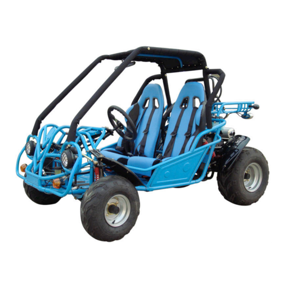
Page 5: Brief Introduction To Off-Road Kart
1. Brief Introduction to Off-road Kart 1.1 Brief Introduction 1 Head Light 2. Main Guard Pole 3. Reverse Gear Device 4. Control Panel 5. Steer Wheel and Steer Pole 6. Rear view mirror 7.Seat 8.Oil Tank 9.Radiator 10. Rear Basket 11 Rear Braking Light 12. Water jug 13. Engine Assembly 14 Rear Frame 15 Rear Wheel 16. -
Page 6: Main Technical Parameter Table
1.2 Engine and Frame Identification Numbers Engine Identification Number: Please remember Engine Identification Number for the check when necessary. The location of Engine Identification Number is at the right side of the engine transmission shell. Frame Identification Number: Frame Identification Number is the unique number for all the vehicles and please make a record for the check when necessary. -
Page 7: Vehicle Assemblage
3. Vehicle Assemblage 1. Take off the front and rear fixing poles by using wrench. 2. Take out Steer Wheel and 6 pan head cruciform slot screws (M6x12) from the plastic bags and install Steer Wheel on the Steer Wheel fixing base (pay attention to the place of Steer Wheel, put the front turning wheels parallel to the rear wheels, let Steer Wheel with 3 strips up face the rear). -
Page 8: Important Events And Safety
4. Important Events and Safety This Off-road Kart is more than a toy and it will cause danger if driving improperly. Please abide by the following suggestions strictly to avoid the injury. ! You mustn’t drive at an excessive speed. You must control the speed properly according to the road situation, the field of vision, your driving experiences and your operating conditions. - Page 9 ! You must drive on the slippery and steep road after mastering the skills of driving for it is dangerous to do so. Attention: driving on the slippery, broken stone or soft road will prolong the braking distance. ! You must drive on the strange road slowly and carefully. ! ...
-
Page 10: Components And Operation Introduction
5. Components and Operation Introduction Location of Components See Picture 1.1 Operation of Components " Steer Wheel Steer Wheel is used to control the direction of the off-road kart and the kart will turn right or left according to the corresponding operation. " ... - Page 11 Gear-engaging Device If there is gear-engaging device in your kart, you must make clear the function and operating ways of each gear so that you can avoid the danger arising from the unexpected running. The back gear device for this kart is located at the right and lower part of Steer Wheel.
- Page 12 Control Panel (Ignition Key and Blanket Switch) Ignition Key Turn the Ignition Key clockwise to the first gear and Braking Indicator will be on. Engine-start: Electric Start (Ignition Key is on Control Panel) > you can start the engine by turning Ignition Key clockwise to the second gear. Blanket Switch If you want to stop the engine, you can press the red Blanket Switch until it stops.
- Page 13 Signal Lamp When the engine system over hot the signal lamp will shine and the buzzer will noise. Turning Lamp Switch Light Switch Horn Switch The horn will be switched on if pressed and off if loosened. Seat You can adjust the location of Seat by moving the hand lever under the cushion.
-
Page 14: How To Drive Off-Road Kart Properly
6. How to Drive the Off-road Kart Properly ! Special Attention: 1. The petrol in the fuel tank and cooling liquid in the radiator have been emptied for the safe transportation. Before starting, please add petrol and cooling liquid to the defined place. - Page 15 c. Adding of cooling liquid When you use it for the first time or when the cooling liquid is not enough, you must add cooling liquid to the radiator. The cooling liquid must be mixed by a specific ratio. It is 60% water and 40% coolant in summer, 50%:50% in winter.
- Page 16 d. Brake Please check the operation of the brake and adjustthe free path when necessary. e. Tires You should check the tightness of the screw bolt and screw nut, the state and the air pressure of the tires to see if it is suitable to drive. f. ...
- Page 17 Steps of Start the Engine Put the vehicle on the flat place. Put Ignition Key to the location of starting the engine, with no more than 10 seconds every time. Please press slightly Gas Pedal and repeat the above-mentioned steps if you fail to start it for several times.
- Page 18 6.7 Stop It will be better for you to choose a flat place to park the vehicle. When parking, you should loosen Gas Pedal and tread Braking Pedal, reducing the speed until it stops. After parking the Kart, you can loosen the brake pedal only after pull up the hand brake so that you can avoid the automatic moving.
- Page 19 Warning: 1. W hen conducting maintenance, please read the operation guidance and warning signs and prepare the necessary tools and auxiliary materials. 2. T he clean, flat, ventilating and bright place should be chosen to conduct the maintenance. The engine should be stopped unless necessary. Please choose the real products if it is necessary to change the components.
-
Page 20: Air Cleaner
7.3 Air Cleaner Routine cleaning is necessary because dust will be left in Air Cleaner during the use. Frequent cleaning should be conducted if driving in the dusty area. 7.3.1 Cleaning of Air Cleaner Take off the plastic protecting jacket. Take off the cover of Air Cleaner. - Page 21 Tire Check The tires of the vehicle are low pressure ones, the proper pressure should be: Front Wheels: 19x7-8 Air Pressure 10 P.S.I Rear Wheels: 22x11-10 Air Pressure 15 P.S.I The over-high or over-low Air Pressure benefits nothing to the proper performance.
-
Page 22: Steering System
Carburetor The idle speed adjusting screw bolt on Carburetor is used to adjust the speed of idle speed. Tighten the screw and the speed will slow down; loosen the screw and the speed will speed up. You must adjust the speed to the lowest stable position when adjusting. -
Page 24: Assembly Instructions
ASSEMBLY INSTRUCTIONS P a r t Name Quantity Boll M8x60 Bolt block Big plastic cover of protecting pole Bend protecting pole Front frame assembly Instruction for the installation: 1 .(3) insert (4). then fix (2) and (3), (4) on (5), with (1) P a r t Name Quantity Bolt M8x60... - Page 25 P a r t Name Quantity Bolt M8x 60 Bolt block Big plastic cover of protecting pole Bend protecting pole Front frame assembly Instruction for the installation: 1. (1) insert (4), then fix (2) and (3), (4) on (5) with (1) P a r t Name Quantity Bolt M8 - 60...
- Page 26 P a r t Name Quantity Bolt M8x60 Bolt block Big plastic cover of protecting pole Bend protecting pole Side protecting pole Instruction for the installation: 1. (3) insert (5), then fix (2) and (3), (5) on (4) with (1) P a r t Name Quantity Bolt M8x60...
- Page 27 P a r t Name Quantity Poll M8X60 Bolt block Min plastic cover of protecting pole Rear shelf assembly Front frame assembly Instruction for the installation: 1. (3) insert (4) then fix (2) and (3), (4) on (5) with (1). P a r t Name Quantity Rear shelf knighthead...
- Page 28 P a r t Name Quantity Fuel vacuum rubber pipe Fuel outlet rubber pipe Fuel tank cock Instruction for the installation: 1. (1) insert (3) 2. (2) insert (3) P a r t Name Quantity Nut M6 Battery Negative wire Poll M6x 12 Instruction for the installation: 1.
-
Page 30: Frame Assembly
FRAME ASSEMBLY Item Id Name: QTY (pcs/set) GK-19-250-01-01 MAIN FRAME 58kg GK-19-250-01-02 FOOTREST PAD GK-19-250-01-03 R.VICE PROTECT POLE GK-19-250-01-04 L.VICE PROTECT POLE GK-19-250-01-05 HEX FLANGE BOLT M8*60 GK-19-250-01-06 CONCAVE WASHER Φ8 GK-19-250-01-07 CONCAVE RUBBER WASHER Φ32 DECORATIVE SPONGE,PROTECT POLE GK-19-250-01-08 Φ32*40*4400... -
Page 32: Wiring Assembly
Item Id Name: QTY (pcs/set) GK-1 9-250-02-01 HEAD LIGHT ASSY GK-19-250-02-01-01 BULB,FR.LIGHT 12V/15W GK-19-250-02-01-02 FR. LIGHT COMP GK-19-250-02-01 03 LOCK NUT M6 GK-19-250-02-01-04 HEX BOLT M6*50 GK-19-250-02-02 FR. TURNING LIGHT ASSY GK-19-250-02-02-01 BULB, TURNING LIGHT 12V/10W GK-19-250-02-02-02 TURNING LIGHT COMP... - Page 33 WIRING ASSEMBLY Item Id Name: QTY (pcs/set) GK-19-250-02-26-02 BULB,TAIL LIGHT 12V10W GK-19-250-02-27 RR.TURNING LIGHT ASSY GK-19-250-02-27-01 TURNING LIGHT COMP GK-19-250-02-27-02 BULB,TURNING LIGHT 12V10W GK-19-250-02-28 SINGING SPARKING RELAY...
- Page 35 ENGINE ASSEMBLY Item Id Name: QTY (pcs/set) GK-1 9-250-03-01 WATER PIPE Φ16*25*1100 GK-19-250-03-02 WATER PIPE Φ16*25*850 GK-19-250-03-03 WATER PIPE Φ4*8*1100 GK-19-250-03-04 ELASTICITY FASTENER Φ8 GK-19-250-03-05 ELASTICITY FASTENER Φ25 GK-19-250-03-06 RUBBER WASHER Φ8*25*8 GK-19-250-03-07 RADIATOR BRACKET GK-19-250-03-08 CONCAVE RUBBER WASHER Φ25...
- Page 36 ENGINE ASSEMBLY Item Id Name: QTY (pcs/set) GK-19-250-03-33-01 FASTENER GK-19-250-03-33-02 INTAKE MANIFOLD GK-19-250-03-33-03 INNER-HEX BOLT M6*18 GK-19-250-03-33-04 STARTER GK-19-250-03-33-05 HEX FLANGE BOLT M6*22 GK-19-250-03-33-06 SPARK PLUG GK-19-250-03-33-07 ENGINE COMP GK-19-250-03-33-08 THERMOSTAT GK-19-250-03-33-09 HEX FLANGE BOLT M6*18 GK-19-250-03-33-10 GAUGE,OIL SEAL GK-19-250-03-34 FLANGE WASHER Φ8*34*3.5...
-
Page 37: Engine Assembly
ENGINE ASSEMBLY Item Id Name: QTY (pcs/set) GK-19-250-03-55 HEX BOLT M8*25 GK-19-250-03-56 ELASTICITY WASHER Φ8 GK-19-250-03-57 FR.SPROCKET 530/16 GK-19-250-03-58 REVERSE GEAR BOX ASSY GK-19-250-03-59 FLANGE BUSH Φ12*20*4.5*24*1.5 GK-19-250-03-60 PLANE WASHER Φ13*24*1.6 GK-19-250-03-61 HEX CONCAVE NUT M12 GK-19-250-03-62 SPLIT PIN Φ2*40 GK-19-250-03-63 CVT BELT 828/22.5... - Page 39 REAR WHEEL ASSEMBLY Item Id Name: QTY (pcs/set) GK-19-250-04-01 DUSTPROOF. RR. WHEEL GK-19-250-04-02 REAR AXLE ASSY GK-19-250-04-02-01 SPLIT PIN Φ3.5*45 GK-19-250-04-02-02 HEX CONCAVE NUT M16 GK-19-250-04-02-03 FLANGE WASHER Φ17*55*5 GK-19-250-04-02-04 PLANE WASHER Φ16*30*2 GK-19-250-04-02-05 BRACKET,RR.WHEEL 1kg GK-19-250-04-02-06 ELASTICITY WASHER Φ10...
-
Page 40: Rear Wheel Assembly
REAR WHEEL ASSEMBLY Item Id Name: QTY (pcs/set) GK-19-250-04-16 BUSH Φ12*18*36 GK-19-250-04-17 RR.SWING ARM 8.1kg GK-19-250-04-18 PROTECTOR,AXLE GK-19-250-04-19 BRACKET,R.RR. WHEEL FENDER GK-19-250-04-20 CHAIN 530/50 GK-19-250-04-21 RR.R.WHEEL ASSY GK-19-250-04-21-01 RR.TIRE 22*11.00-10 7.3kg GK-19-250-04-21-02 RR.RIM 3.4kg... -
Page 42: Front Wheel Assembly
FRONT WHEEL ASSEMBLY Item Id Name: QTY (pcs/set) GK-19-250-05-01 HEX FLANGE BOLT M6*16 GK-19-250-05-02 LOCK NUT M6 GK-19-250-05-03 FR.WHEEL FENDER GK-19-250-05-04 BRACKET, L. FR. WHEEL FENDER GK-19-250-05-05 HEX BOLT M6*40 GK-19-250-05-06 DUSTPROOF, FR. WHEEL GK-19-250-05-07 SPLIT PIN Φ3*40 GK-19-250-05-08 HEX CONCAVE NUT M14 GK-19-250-05-09 BUSH Φ17*27*8... -
Page 44: Steering Assembly
STEERING ASSEMBLY Item Id Name: QTY (pcs/set) GK-19-250-06-01 THROTTLE PEDAL ASSY GK-19-250-06-01-01 THROTTLE PEDAL GK-19-250-06-01-02 PAD,THROTTLE PEDAL GK-19-250-06-01-03 LOCK NUT M5 GK-19-250-06-01-04 HEX FLANGE BOLT M5*12 GK-19-250-06-01-05 LOCK NUT M8 GK-19-250-06-01-06 HEX STEP BOLT M8*14*12*130 GK-19-250-06-01-07 HEX NUT M8 GK-19-250-06-01-08... - Page 45 STEERING ASSEMBLY Item Id Name: QTY (pcs/set) GK-19-250-06-09 REVERSE CABLE 2580*2730 GK-19-250-06-10 HYDRAULIC BRAKE ASSY [3 IN 1] GK-19-250-06-10-01 HYDRAULIC BRAKE COMP GK-19-250-06-10-02 FR.BRAKE SHOE GK-19-250-06-10-03 RR.BRAKE SHOE GK-19-250-06-10-04 HEX FLANGE BOLT M8*20 GK-19-250-06-10-05 HEX FLANGE BOLT M8*35 GK-19-250-06-10-06 LOCK NUT M8...
-
Page 47: Seat Assembly
SEAT ASSEMBLY Item Id Name: QTY (pcs/set) GK-19-250-07-01 SEAT GK-19-250-07-01-01 R.SEAT GK-19-250-07-01-02 L.SEAT GK-19-250-07-01-03 BRACKET,SEAT GK-19-250-07-01-04 ADJUSTER,SEAT GK-19-250-07-01-05 SKIDPROOF NUT M8 GK-19-250-07-01-06 ELASTICITY WASHER Φ8 GK-19-250-07-01-07 PLANE WASHER Φ8 GK-19-250-07-01-08 HEX BOLT M8*50 GK-19-250-07-01-09 HEX BOLT M8*25 GK-19-250-07-02 SAFE BELT ASSY... -
Page 48: Rear Axle Assembly
REAR AXLE ASSEMBLY Item Id Name: Description QTY (pcs/set) REAR 93MM SPACE IS FOR NEW TYPE(INTERNAL TRANY). GK-19-250-4-2-15 AXEL 140MM SPACE IS FOR OLD TYPE(EXTERNAL TRANY).
Need help?
Do you have a question about the GK-19 and is the answer not in the manual?
Questions and answers