Table of Contents
Advertisement
Quick Links
SERVICE MANUAL
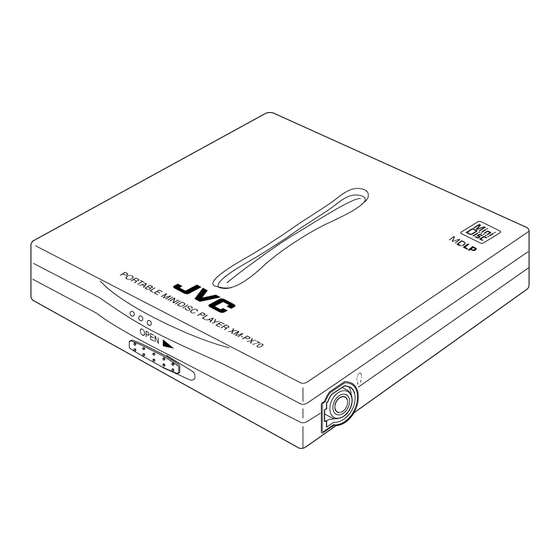
PORTABLE MINIDISC PLAYER
XM-PX70WT/BU/PN
Contents
Safety Precautions
MD pick up is exchanged
Attention when parts
COPYRIGHT
are exchanged
2001 VICTOR COMPANY OF JAPAN, LTD.
XM-PX70WT/BU/PN
Area Suffix
UB
1-2
1-3
1-4
1-9
1-10
1-10
1-11
1-24
Hong Kong
No.20897
Jan. 2001
Advertisement
Chapters
Table of Contents

Related Manuals for JVC XM-PX70WT


Summary of Contents for JVC XM-PX70WT
-
Page 1: Table Of Contents
XM-PX70WT/BU/PN SERVICE MANUAL PORTABLE MINIDISC PLAYER XM-PX70WT/BU/PN Area Suffix Hong Kong Contents Safety Precautions Attention when MD pick up is exchanged Disassembly method Adjustment method Maintenance of laser pickup 1-10 Replacement of laser pickup 1-10 Description of major ICs 1-11... - Page 2 XM-PX70WT/BU/PN 1. This design of this product contains special hardware and many circuits and components specially for safety purposes. For continued protection, no changes should be made to the original design unless authorized in writing by the manufacturer. Replacement parts must be identical to those used in the original circuits.
- Page 3 XM-PX70WT/BU/PN Attention when MD pickup is exchanged 1. About the static electricity protection measures The laser diode in the traverse unit (optical pick up) is easy to be destroyed by clothes and the human body to the electrified static electricity.
-
Page 4: Attention When
XM-PX70WT/BU/PN MD door assembly Disassembly method Removing the MD door assembly (See Fig.1 and 2) Shift the door lever to open the door. Remove the four screws A and detach the MD door assembly from the main body. Door lever Fig.1... - Page 5 XM-PX70WT/BU/PN Chassis assembly Removing the chassis assembly (See Fig.5 to 7) Side arm (R) Prior to performing the following procedure, remove the MD door assembly and the holder assembly. Open the battery lid. Release the tab d and pull out the battery lid.
- Page 6 XM-PX70WT/BU/PN Removing the main board and the Battery holder CN401 battery holder (See Fig.8 and 9) Soldering f CN301 Prior to performing the following procedures, remove the MD door assembly, the holder assembly and the chassis assembly. ATTENTION: Before disconnecting the flexible wire...
- Page 7 XM-PX70WT/BU/PN <Removal of the MD Chassis assembly mechanism section> Worm gear Lead screw Slit washer Prior to performing the following procedures, remove the MD door assembly, the holder assembly, the chassis assembly and the main board. Part i Removing the spindle motor (See Fig.11)
- Page 8 XM-PX70WT/BU/PN Removing the feed motor (See Fig.14) Soldering k Peel off the adhesive tape j on the flexible wire on the underside of the feed motor. Unsolder soldering k connecting the flexible wire to the feed motor. Remove the two screws M attaching the feed motor.
-
Page 9: Adjustment Method
XM-PX70WT/BU/PN Adjustment method This model is auto adjustment by Remote Controller. Please adjust the attached remote controller. Equipments----- 1. Remote controller 2. DC power supply 3. Laser power meter 4. MO disc (AU-1) 5. Pre master disc (TGYS 1) <Test mode setting method>... -
Page 10: Maintenance Of Laser Pickup
XM-PX70WT/BU/PN Maintenance of laser pickup Replacement of laser pickup (1) Cleaning the pick up lens Before you replace the pick up, please try to Turn off the power switch and,disconnect the clean the lens with a alcohol soaked cotton power cord from the ac outlet. -
Page 11: Description Of Major Ics
XM-PX70WT/BU/PN Description of major ICs JCV8002-W (IC601) : Head phone amp 1. Pin layout 2. Block diagram Vref BEEP BEEP Vref Vref IN B BST1 IN A BEEP BST2 OUT B BEEP OUT A CUT A 3. Pin function Symbol... - Page 12 XM-PX70WT/BU/PN CXA2588R (IC300) : RF amp. 1. Pin layout & block diagram 31 30 36 35 34 33 32 29 28 ADIP Amp TE/SE Amp PEAK 37 24 Vcc FE Amp RF 38 23 3TADJ RFAGC 39 22 EQADJ AGCI 40...
- Page 13 XM-PX70WT/BU/PN CXA8059Q (IC450) : Motor driver 1. Pin layout 2. Block diagram 1-13...
- Page 14 XM-PX70WT/BU/PN 3.Pin function Symbol Function PGND The GND to guard the power stage. The terminal to detect the voltage. The terminal to supply the voltage for the power stage. CPOUT The terminal to connect the capacitor in the final charge pump.
- Page 15 XM-PX70WT/BU/PN CXD2672GA(IC351):DSP 1.Pin layout AVS1 ASYI DVSS1 LDDR DTRF VSI02 ADFG ADRB AVS2 ADI0 PEAK FILI ABCD CLTV APCR CKRF FOCN ADRT BIAS ASYO XWE TST6 AVD2 AUX1 BOTH FILO XLRF VDI02 DCHG AVD1 MVCI TFDR TRDR DVDD1 FRDR FFDR VDC4...
- Page 16 XM-PX70WT/BU/PN 2.Pin function(2) Symbol Function Pin No. XLAT Micon serial bus latch input SRDT Micon serial bus data read out output SENS Internal output of micon serial bus address VSC0 Internal logic GND SQSY PTGR=0 ADIPsink output / PTGR=1 DISC SUB-Q sink output...
- Page 17 XM-PX70WT/BU/PN 2.Pin function (3) Symbol Function Pin No. VSIO1 2.5V I/O sel Vss External DRAM address output ADIO1 2.5V I/O sel VDD U-10 External DRAM address output T-10 External DRAM address output R-10 External DRAM address output U-11 IXOE Open...
- Page 18 XM-PX70WT/BU/PN 2.Pin function (4) Symbol Function Pin No. E-17 VSIO2 2.5V I/O Vss E-16 F0CN Filter cutoff control output E-15 VDIO2 2.5V I/O VDD D-17 DTRF Controller data output D-16 CKRF Controller clock output D-15 XLRF Controller latch output A-17...
- Page 19 XM-PX70WT/BU/PN AK93C55BH-W (IC502) : EEPROM 1. Pin layout 2.Pin function Pin name Fnction Chip select Serial data clock Serial data input Serial data output Program enable Ground Power supply Not connected 3. Block diagram DATA REGISTER R/W AMPS AUTO ERASE...
- Page 20 XM-PX70WT/BU/PN IC-PST3421U-X(IC504):System reset 1.Pin layout 2.Pin function Symbol Function VOUT 1 VOUT Reset signal output terminal Power supply terminal Non connect VSS terminal 3.Block diagram VOUT Vref 1-20...
- Page 21 XM-PX70WT/BU/PN MPC17A139MTB-X (IC400) : 4ch bridge driver 1.Pin layout 2.Pin function Driver section PS,OE INPUT OUTPUT 1~4 X:Don't Care Z:High Impedance Clock detector section OSC circuit Auto Syncro Stop 3.Block diagram Pre-driver Pre-driver Pre-driver Pre-driver Control Control Control Control 1-21...
- Page 22 XM-PX70WT/BU/PN UPD784225GK-617C(IC501):CPU 1.Pin layout 2.Pin function Function Function Symbol Symbol Non connect ANI5 Non connect ANI6 Non connect Non connect SPSEL Test terminal AVSS Non connect Test terminal DPON Voltage adjust Non connect VADJ Analog reference voltage Test terminal AVREF1...
- Page 23 XM-PX70WT/BU/PN XC6367B101M-X (IC901,IC921,IC941):Regulator 1.Pin layout 2.Pin function Pin No. Symbol Function Output voltage setting Power supply Chip enable Ext. Tr connection 3.Block diagram Phase Compensation Error Amp. Comparator Buffer, Driver Vref with Ramp Wave PWM/PFM Soft Start, Generator, Controler 1-23...
- Page 24 XM-PX70WT/BU/PN Attention when parts are exchanged The 2 bottom case and 35 MD door assembly are indicated on Exploded view of general assembly, there are two kind of parts at same color. When you exchange parts confirm the marking and change same parts.
- Page 25 XM-PX70WT/BU/PN VICTOR COMPANY OF JAPAN, LIMITED AUDIO & COMMUNICATION BUSINESS DIVISION PERSONAL & MOBILE NETWORK BUSINESS UNIT. 10-1,1chome,Ohwatari-machi,Maebashi-city,371-8543,Japan Printed in Japan (No.20897) 200101(O)
-
Page 26: Block Diagram
XM-PX70WT/BU/PN Block diagram CN601 CN301 CN401... - Page 27 XM-PX70WT/BU/PN Standard schematic diagram Main amp section Standard schematic diagram C373 Main amp section R376 3.3k R377 R372 100k C376 0.47 R601 470k C614 4.7/4 C613 R603 470k 10/6.3 R604 470k BOTM ABCD C602 C319 C318 TP307 10/6.3 0.001 NTCT...
- Page 28 XM-PX70WT/BU/PN XM-PX70WT/BU/PN Printed circuit board Forward side Reverse side CN401 C406 L400 S504 C411 C412 R463 IC400 C452 L404 R459 R460 R465 C453 IC450 C300 C462 Q300 C464 R303 C325 R305 R454 R338 R341 C301 C302 S503 R306 CN301 C309...
- Page 29 XM-PX70WT/BU/PN < M E M O >...
- Page 30 XM-PX70WT/BU/PN PARTS LIST [ XM-PX70WT/BU/PN ] * All printed circuit boards and its assemblies are not available as service parts. Area suffix UB -------------------- Hong Kong - Contents - Exploded view of general assembly and parts list MD mechanism assembly and parts list...
-
Page 31: Exploded View Of General Assembly And Parts List
XM-PX70WT/BU/PN Exploded view of general assembly and parts list Block No. - Page 32 XM-PX70WT/BU/PN Parts list (General assembly) Block No. M1MM Item Parts number Parts name Q'ty Description Area ------------ FLM-FPM LV10423-005A BOTTOM CASE XM-PX70BU LV10423-205A BOTTOM CASE XM-PX70BU LV10423-006A BOTTOM CASE XM-PX70PN LV10423-204A BOTTOM CASE XM-PX70WT LV10423-206A BOTTOM CASE XM-PX70PN LV41974-001A INSULATOR...
-
Page 33: Md Mechanism Assembly And Parts List
XM-PX70WT/BU/PN MD mechanism assembly and parts list Block No. FLM-FPM Grease = FL-7750 = CFD-4007HY2 = FG-87HS = 948P Both side 2.1 0.1mm Parts list (MD mechanism) Block No. M2MM Item Parts number Parts name Q'ty Description Area LV20882-001A CHASSIS ASS'Y... - Page 34 XM-PX70WT/BU/PN Electrical parts list (Main board) Block No. 01 Item Remarks Item Remarks Parts number Parts name Area Parts number Parts name Area C 62 NCB31HK-102X C CAPACITOR C 500 NCB21AK-105X C CAPACITOR C 63 NCB31HK-102X C CAPACITOR C 503...
-
Page 35: Electrical Parts List
XM-PX70WT/BU/PN Electrical parts list (Main board) Block No. 01 Item Remarks Item Remarks Parts number Parts name Area Parts number Parts name Area Q 63 2SC4617/QR/-X TRANSISTOR R 356 NRSA6AJ-0R0W MG RESISTOR Q 64 2SC4617/QR/-X TRANSISTOR R 357 NRSA6AJ-0R0W MG RESISTOR... - Page 36 XM-PX70WT/BU/PN Electrical parts list (Main board) Block No. 01 Item Remarks Parts number Parts name Area R 928 NRSA6AD-104W MG RESISTOR R 929 NRSA6AD-683W MG RESISTOR R 941 NRSA6AJ-0R0W MG RESISTOR R 942 NRSA6AJ-474W MG RESISTOR R 943 NRSA6AJ-472W MG RESISTOR...
-
Page 37: Packing Materials And Accessories Parts List
XM-PX70WT/BU/PN Packing materials and accessories parts list Block No. Block No. A1,A10... -
Page 38: Parts List
XM-PX70WT/BU/PN Parts list (Packing) Block No. M3MM Item Parts number Parts name Q'ty Description Area LV30245-003A POLY BAG FOR SET LV32523-001A CARTON XM-PX70WT LV32523-003A CARTON XM-PX70PN LV32523-002A CARTON XM-PX70BU LV31930-002A PAPER CUSHION FOR CARTON (Accessories) Parts list Block No. M4MM...
Need help?
Do you have a question about the XM-PX70WT and is the answer not in the manual?
Questions and answers