Advertisement
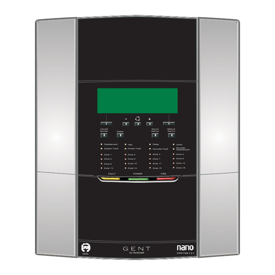
Nano panel
Cancel
Buzzer
Reset
Disablement
Test
System Fault
Power Fault
Zone 1
Zone 2
Zone 5
Zone 6
Zone 9
Zone 10
Zone 13
Zone 14
FAULT
by Honeywell
042bc
The Nano panel is designed to meet the requirements of
EN54-2 : 1997 and EN54-4 :1997. The panel can accommodate
a loop circuit of analogue addressable devices, like fire sensors,
sounders, manual call points and interface units. The panel gives
local visual and audible indications of system events means of
indicators, a message display and an integral sounder. An
integral mains derived supply provides power to the panel and
the loop circuit in normal conditions and the integral batteries
provides a standby supply for up to 24 hours with 0.5hours of
alarms should the mains supply fail. The controls are PIN code
protected. The panel is designed for surface and semi flush
mounting and facilitates both rear and top cable entry points.
www.acornfiresecurity.com
Sound
Silence
Alarms
Alarms
Delay
Verify
Sounder
Sounder Fault
Disablement
Zone 4
Zone 3
Zone 7
Zone 8
Zone 11
Zone 12
Zone 16
Zone 15
POWER
FIRE
EN54 Parts 2 & 4
www.acornfiresecurity.com
Features
¨
Single loop fire control panel.
¨
Up to 127 addressable devices can be connected to a
loop circuit, devices like sensors, call point and
interface units.
¨
Two master alarm circuits.
¨
RS485 Port to connect to repeat indicator panel(s).
¨
RS232 Port to connect to an external printer.
¨
USB Port to connect to a Commissioning computer.
¨
Fire Output - One set of clean voltage-free change over
contacts.
¨
Fault Output - One set of clean voltage-free change
over contacts.
¨
Class Change input that actions class change signal to
selected sectors
¨
Evacuate input that actions all alarm sounders
including master alarms and fire output
¨
Standby supply to power the system via batteries for
24 hours plus 0.5 hour alarm load.
¨
Alphanumeric LCD with back light to display event
information.
¨
Integral 16 zone LEDs (with First fire zone LED
flashing).
¨
LED lights for event indications.
¨
Local audible buzzer for event announcement.
¨
Push buttons for essential controls and menu driven
commands.
Nano System
Advertisement
Table of Contents

Related Manuals for Gent Nano panel


Summary of Contents for Gent Nano panel
- Page 1 EN54 Parts 2 & 4 042bc ¨ Local audible buzzer for event announcement. The Nano panel is designed to meet the requirements of ¨ Push buttons for essential controls and menu driven EN54-2 : 1997 and EN54-4 :1997. The panel can accommodate commands.
-
Page 2: Technical Data
www.acornfiresecurity.com Installation instructions Master alarm 2 - Master alarm circuits Technical data circuits and operating at 24 volt nominal, Control panel fuses 200 mA maximum per circuit Standard Designed to EN54-2 : 1997 MA1 - Fuse FS2 250mA AS MA2 - Fuse FS3 250mA AS Approval LPCB approved Both fuses are Ceramic type... - Page 3 www.acornfiresecurity.com Nano System Power supply Controls at As for controls at Access level 1 Standard Designed to EN54-4 : 1997 plus controls for: Access level 2 ¨ (Customer mode) Mains supply 230V 50Hz protected by: Cancel buzzer voltage and fuses FS3 Fuse - 3.15A (T) 250V ¨...
-
Page 4: Panel Installation
Installation instructions Panel installation The Nano panel is supplied fully assembled, it is important to check the contents to ensure all the parts are supplied. Note the 2 x 12V 7Ah batteries are supplied in a separate pack. Parts in the Spares packages Quantity Fuse T3.15A H 250V 20mm x 5mm Ceramic... - Page 5 www.acornfiresecurity.com Nano System How to mount the backbox and dedicated cable entry points & Unused knockouts that have been removed should not be left open. Knockout the required dedicated cable entry points from the back box. Use the correct method of knocking out the entry points, as illustrated below.
- Page 6 www.acornfiresecurity.com Installation instructions Flush Mounting the backbox The control panel may be flush mounted using a flush surround NANO-FLUSH. Cut out an aperture in the wall to allow the flush surround to be fitted, see diagram for dimension of the aperture. Using the fixing holes on the flush surround, secure it into the aperture side walls.
-
Page 7: Wiring Test
www.acornfiresecurity.com Nano System Cable termination on enclosure The wire length between the cable termination and point of connection must be as short as possible. Cable earth drain wire, where applicable, must be connected to the respective drain termination point. Softskin (Fire Tuf) CABLE TERMINATION Master Fire... -
Page 8: Mains Supply
www.acornfiresecurity.com Installation instructions Mains supply & Ensure that the mains supply cable enters the panel through a dedicated cable entry, located adjacent to the mains terminal block and that is also segregated from loop wiring. " These fire alarm system products are not designed to be powered from IT Power systems. All mains powered equipment must be earthed. - Page 9 www.acornfiresecurity.com Nano System Terminals for external circuits on Main Control Board The Main Control Board (MCB) holds all the terminals for the connection of fire alarm loop circuit, master alarms, fire and fault relays, class change, evacuate input and repeat indicator panel. EXT.EVAC.
-
Page 10: Main Control Board
www.acornfiresecurity.com Installation instructions Device loop circuit The device loop circuit can accept connection of addressable devices, up to 127 maximum. To maintain earth continuity on the loop, the loop cable screen must be continued through each system device, whether the earth is connected to a device or not. "... - Page 11 www.acornfiresecurity.com Nano System Master alarm circuits Common Fault contacts There are two MASTER ALARM circuits that can accept the The control panel has a COMMON FAULT relay having voltage connection of conventional alarm sounders including the free contacts that can be used to signal external equipment. The conventional Speech-Sounder-Strobe S products.
- Page 12 www.acornfiresecurity.com Installation instructions Fire Output contacts Repeat indicator panel The control panel has a FIRE OUTPUT relay having voltage free Up to four REPEAT INDICATOR PANELS can be connected contacts that can be used to switch plant equipment, such as lift directly to the fire panel to its RS485 Port.
- Page 13 www.acornfiresecurity.com Nano System External Evacuation input RS232 Port The EVACUATION INPUT function is activated on operation of The RS232 port of the fire panel can be configured to allow an external switch wired in the manner shown below. The switch connection of external printer.
- Page 14 www.acornfiresecurity.com Installation instructions Battery installation The batteries are fitted inside the backbox and connected up in the manner shown, however the final connection to power up the panel is made during system commissioning, which is done by the servicing organisation. To fit the batteries inside the panel enclosure: Open out the two tabs on the electronic module at positions and lift open the 'LCD assembly' to an angle 45...
-
Page 15: Outer Cover
www.acornfiresecurity.com Nano System On completion of panel installation On completion of all cable installation ensure the wires are neatly stored in the space above the electronics module. Fit the 'outer cover' by hooking it over the top edge of the 'backbox' and then close the bottom of the 'outer cover' onto the 'backbox' and secure the cover by the captive screws using the allen key.
Need help?
Do you have a question about the Nano panel and is the answer not in the manual?
Questions and answers