
Subscribe to Our Youtube Channel
Summary of Contents for Menvier Security MF9300
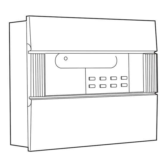
- Page 1 Menvier Fire System MF9300 Eight and sixteen zone control panels Installation and User Instructions and Systems Log...
-
Page 2: Accessories
IMPORTANT THIS MENVIER FIRE PANEL IS DESIGNED TO BE USED WITH POLARISED AND SUPPRESSED BELLS. DO NOT USE WITH UNSUPPRESSED BELLS, UNSUPPRESSED RELAYS OR NON-POLARISED SOUNDERS OR STROBES ETC. DO NOT CONNECT 230V MAINS DIRECTLY TO THE PCB. ELECTRICAL INSULATION TESTS SHOULD NOT BE CARRIED OUT WITH THE CABLES CONNECTED TO THE PANEL OR DETECTORS OR SOUNDERS. - Page 3 IMPORTANT NOTICE RELATING TO INSTALLING AND SERVICING THE PANEL WHENEVER POWERING UP THE PANEL FROM A COMPLETELY POWERED DOWN STATE, I.E. NO MAINS OR BATTERY SUPPLY CONNECTED, THE SYSTEM RESET BUTTON MUST BE PRESSED - SEE FIG. 2 FOR THE LOCATION OF THIS PUSH BUTTON.
-
Page 4: Table Of Contents
TABLE OF CONTENTS ACCESSORIES OVERVIEW SYSTEM OPERATION OPERATING THE PANEL SPECIALISED OPTIONS APPENDIX A Fire Alarm Log Details Of Installation Details Of Modifications APPENDIX B Faults - How To Recognise Them & What Action To Take Fires - How To Recognise Them APPENDIX C Installation Of The MF9308 Control Panels Using The Panel Interfaces... -
Page 5: Overview
OVERVIEW This document gives details of how to install, test, use and maintain operation of your MF9300 fire alarm panel. SYSTEM OPERATION What To Do At A Glance The following information tells you what the various indicators, visible on the front panel, mean and how you should react to them. -
Page 6: Operating The Panel
OPERATING THE PANEL General The panel operates in 1 of 2 modes - Normal mode or Supervisor mode. In Normal mode the Supervisor mode LED is extinguished. In Supervisor mode the Supervisor LED is continuously ON. Control of the facilities at the panel is available via the keyboard. A key press is acknowledged by a blip of the internal panel buzzer. - Page 7 Reset: This facility allows you to reset the panel. When hit, all panel indicators will light and the internal panel buzzer will sound. On the MF9304 the Fault relay output will also activate. On releasing the button the lights will extinguish, the buzzer will silence and the relay output will deactivate.
- Page 8 The fact that a zone is in test will not prevent the panel from recognising and acting upon fires or faults in other zones. To take a zone out of the test mode you must go into the Supervisor mode and then press Reset.
-
Page 9: Specialised Options
SPECIALISED OPTIONS Certain additional features may be set up by the service provider at the commissioning stage. They are as follow: Non-latching Zone This feature is available on zone 1 and is selectable at commissioning by use of a switch in the panel (see Appendix C for selecting this feature). - Page 10 PAGE 9...
- Page 11 PAGE 10...
- Page 12 PAGE 11...
- Page 13 PAGE 12...
- Page 14 PAGE 13...
- Page 15 PAGE 14...
- Page 16 PAGE 15...
- Page 17 PAGE 16...
- Page 18 PAGE 17...
-
Page 19: Details Of Installation
DETAILS OF INSTALLATION No. of Call No. of Smoke No. of Heat Zone No. Location Points Detectors Detectors TOTAL CURRENT No. OF SOUNDER BELLS ELECTRONIC TOTAL ALARM LOAD: OTHER OTHER DETAILS OF EQUIPMENT: THIS SYSTEM HAS BEEN INSTALLED IN ACCORDANCE WITH THE REQUIREMENTS OF EN54 SIGNED DATE THIS SYSTEM HAS BEEN COMMISSIONED IN ACCORDANCE WITH THE REQUIREMENTS OF... -
Page 20: Faults - How To Recognise Them & What Action To Take
APPENDIX B Faults - How To Recognise Them And What Action To Take All fault conditions on the fire alarm panel will be indicated by the flashing of the general fault indicator (positioned immediately below the large red fire indicator) and the activation of at least one other fault-specific indicator. -
Page 21: Installation Of The Mf9308 Control Panels
Manual call points used in the system (MBG913/MBG914) are polarised. Use the connection details accompanying the manual call points in order to ensure that the correct polarity of connections is observed at all times. Also, make sure that the 'MF9300' terminals are used on the manual call points. -
Page 22: Using The Panel Interfaces
2. Connect the batteries together using the battery connectors contained in the accessories bag - note the polarity of the connections on the assembly diagram (Fig.1). Fit the batteries into the battery compartment of the rear enclosure. 3. Ensure that all external wiring that is to be used is available within the back box and connect them to the correct terminal blocks on the interface board (use Fig.3 for guidance). - Page 23 Class Change A pair of contacts are provided for a class change facility. By short circuiting these contacts via a switch, pulse unit, time clock or by other means, the alarms will sound without illuminating the fire lights. The alarms will cancel when the short circuit is removed. No voltage should be applied to these terminals.
-
Page 24: Setting System Parameters
Setting System Parameters Certain facilities that can be set up by the service provider at commissioning. They are as follows: Non-latching Zone To enable this facility gain access to the service area of the panel and push the Non-latching zone switch down (Fig.2). - Page 25 PAGE 25...
- Page 26 PAGE26...
- Page 27 Repeater Transmit Repeater Ground To volt free contacts Class change (note 2) Auxiliary common output (note 2) Auxiliary 24v DC output Earth PAGE 27...
-
Page 28: Technical Specifications
TECHNICAL SPECIFICATIONS MF9308 MF9316 No. of zones No. of alarm circuits Mains input voltage 230 VAC +/- 10% 50Hz System operating voltage 24 VDC Monitoring Zones Open, short circuit and detector removed Alarms Open, short circuit and detector removed End of line elements Zones 12K resistor supplied with panel Alarms... - Page 29 For service Tel: please call: Service agreement number Cooper Lighting and Security Ltd. Lighting and Security Wheatley Hall Road, Doncaster, South Yorkshire, DN2 4NB, United Kingdom Sales General Export Tel: +44 (0)1302 - 303303 +44 (0)1302 - 321541 +44 (0)1302 - 303250 Fax: +44 (0)1302 - 367155 +44 (0)1302 - 303220...
Need help?
Do you have a question about the MF9300 and is the answer not in the manual?
Questions and answers