Table of Contents
Advertisement
Quick Links
- 1 Locator in Complete Circuits
- 2 In Open Circuits (One Pole Application)
- 3 Locating and Tracing of Lines, Sockets, Switches and Junctions in House Installations Circuits
- 4 Locating of Line Interruptions
- 5 Tracing Conductors Within the Soil (Single-Pole Application)
- 6 Setting the Codes
- 7 Technical Data
- Download this manual
Advertisement
Table of Contents

Related Manuals for Fluke 2042


Summary of Contents for Fluke 2042
- Page 1 ® Model 2042 Cable Locator Users Manual PN 2438531 May 2005 (English) © 2005 Fluke Corporation. All rights reserved. Printed in China.
- Page 2 Parts, product repairs, and services are warranted for 90 days. This warranty extends only to the original buyer or end-user customer of a Fluke authorized reseller, and does not apply to fuses, disposable batteries, or to any product which, in Fluke's opinion, has been misused, altered, neglected, contamina- ted, or damaged by accident or abnormal conditions of operation or handling.
-
Page 3: Table Of Contents
Fluke 2042 Table of Contents Page General Information / Introduction /Scope of Supply ........4 Product Description ..................4 Scope of supply .................... 5 Transport and Storage .................. 5 Safety Measures.................... 5 Appropriate Usage ..................7 Operation Elements and Connections ............7 Carrying out measurement................ -
Page 4: General Information / Introduction /Scope Of Supply
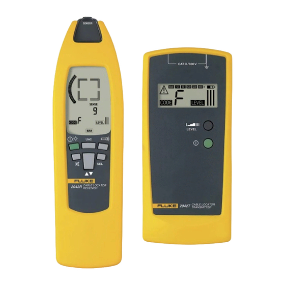
Users Manual or to comply with the warnings and references contained herein can result in serious bodily injury or instrument damage. General Information / Introduction /Scope of Supply The FLUKE Cable Locator is a portable measurement instrument and can be used to detect or trace conductors. Product Description The FLUKE Cable Locator consists of a transmitter and a receiver. -
Page 5: Scope Of Supply
Safety Measures The FLUKE Cable Locator has been constructed in accordance with the safety regulations for elect- ronic test and measurement instruments and has left the factory in safe and perfect condition. To maintain this condition, the user must pay attention to the safety references contained in this Users Manual. - Page 6 Fluke 2042 Safety Measures Prior to usage, inspect instrument for external damage. Prior to any operation, ensure that con- necting leads used and electronic load are in perfect condition. If the operator’s safety is no longer ensured, the instrument is to be put out of service and pro- tected against use.
-
Page 7: Appropriate Usage
Fluke 2042 Users manual Appropriate Usage The instrument may only be used under those conditions and for those purposes for which it was conceived. For this reason, in particular the safety references , the technical data including environmental conditions and the usage in dry environments must be followed. - Page 8 Fluke 2042 Users manual Transmitter – Display 3a) Transmitted Code 3b) Display for external voltage (i.e. 50 V) 3c) External voltage detection The integrated foreign voltage detection fea- ture is not appropriate to check (if the con- nection is live) ! Tor check that the system is live, use an appropriate voltage tester (e.g.
- Page 9 Fluke 2042 Users manual 15) Toggle button for manual selection of the sensitivity upward selection downward selection This button remains inactive when selecting the mains voltage detection mode. Automatic Mode (Standard setting after switch-on) If the automatic mode is selected the message "SIGNAL" is dis- played.
- Page 10 Fluke 2042 Users manual Receiver – Display 9 a) Display to indicate that the acoustic display is switched off 9 b) Symbol to indicate the active LCD illumination 9 c) Information transmitted by the transmitter (transmission code and battery charge conditi-...
-
Page 11: Carrying Out Measurement
Fluke 2042 Users manual Cable Locator Mode a) Automatic mode b) Manual mode c) Selective Mode Mains Voltage Detection Carrying out measurement The transmitter should be connected between phase and neutral. First verify that the ground wire is in compliance with the VDE 100 for, when connectiong the transmitter from phase to ground, all parts being connected to ground could be live during failures (in cases where the earth resistance does not comply with the regulations). -
Page 12: Theoretical Functional Principle
Thus a complete circuit is created. Then, the transmitter is sup- plied by the built-in battery. From now on, we will call this operation double pole application. The FLUKE Cable Locator can only detect or locate lines, which are connected correctly in ac- cordance with the physical principle described. - Page 13 Fluke 2042 Users manual Connect terminal (2) of the transmitter to a suitable ground. All other cable leads must also be con- nected to the transmitter and the same ground. Switch in the transmitter via push button (5). Set the transmitter to "LEVEL I" via button (4). The transmitter function is indicated via the flashing of the signal lamp (3).
-
Page 14: In Open Circuits (One Pole Application)
Fluke 2042 Users manual To perform the test, it is good to mark the location of the artificial interruption on the opposite side of the wall. Select the sensitivity using button (15) to make sure that the signal "F” is only just receiva- ble. -
Page 15: Locating And Tracing Of Lines, Sockets, Switches And Junctions In House Installations Circuits
Fluke 2042 Users manual The tracing depth amounts to 0...0,5 meters..The tracing depth depends of medium and application When connecting in live circuits, safety regulations must be followed. The switching with button 4 from »LEVEL I« to »LEVEL III« the sensitvity of Distance is increased up to factor 5. -
Page 16: Locating Of Line Interruptions
Fluke 2042 Users manual Locating of line interruptions (one-pole application) Requirements: • The circuit must be dead. • All lines which are not required must be connected to the auxiliary ground in accordance with figure 8. • Connect transmitter to one lead and to an neutral according to figure 8. - Page 17 Fluke 2042 Users manual If the transmitters are connected in accordance with the figure 13, the receiver indicates "C" at the left side of the line interruption. If you continue further than the interruption, to- wards the right, the receiver displays "F". If you are directly above the interruption, no line code is displayed, due to the overlapping of both transmitter signals.
-
Page 18: Error Detection For A Electrical Floor Heating (One-Pole Application)
Fluke 2042 Users manual Error detection for a electrical floor heating (one-pole application) Please also note the connection conditions. If a shield mat or shield wiring is located above the heating wires, no ground connecti- on may exist. If required, separate the shield from the ground connection. -
Page 19: Locating Fuses (Dual-Pole Application)
Fluke 2042 Users manual Locating Fuses (dual-pole application) When connecting in live circuits, the safety directions must absolutely be respected. Insert into the current circuit of a multifamily residential structure within a socket between L1 and N and switch the transmitter to "LEVEL I". -
Page 20: Tracing Installed Water And Heating Pipes (One-Pole Application)
Fluke 2042 Users manual Should the short-circuit resistance amount to more than 20 Ohm, you can try the experiment to de- tect the error location by means of the line interruption mehtode. You can try with sufficient energy to determine the error location (low ohmic connection) or to burn it in a way ensuring a line interrup- tion. -
Page 21: Detecting The Direction Of Water And Heating Pipes Already Installed
Fluke 2042 Users manual Detedting the direction of water and heating pipes already installed (one-pole application) Requirements: • The respective water and heating pipes must be suitably grounded. • Connect the transmitter according figure 13. • Carry out this example as described in the application example. -
Page 22: Following Lines With Higher Location Depth (Dual-Pole Application)
Fluke 2042 Users manual Following lines with higher location depth (dual-pole application) If the dual-pole application is carried out on multi-wire cables (e.g. NYM 3x1.5mm2), the location depth is widely limited. The reason is that the go-and-return lines are installed very closely. Thus, a strong distortion of the magnetic field occurs. -
Page 23: The Reach Will Be Improved When Seeking The Tension
Fluke 2042 Users manual • Set the receiver to automatic mode. • Now, search or trace the conductor by means of the sig- nal intensity (9e + 9j) displayed. When circling the recei- ver slowly across the conductor to be searched, the dis- play values change considerably. -
Page 24: Sorting Or Determination Of Conductors Already Installed
Fluke 2042 Users manual Sorting or determination of conductors already installed (double-pole application) Requirements: • Any exisiting circuits within the cable must be voltage- free. • The lead terminals must be twisted and electrically con- nected between each other • You need several transmitters, with different transmitter signals (A to F or 0 to 9). -
Page 25: Setting The Codes
Fluke 2042 Users manual Setting the Codes Make sure that the instrument is switched off before setting the codes. • Remove the batteries from the transmitter in compliance with section 8.2. • Remove the jumper within the battery case (6 a). - Page 26 Fluke 2042 Users manual Reverse polarity of batteries may destroy the instrument. Furthermore, they may explode or ignite Only use batteries as described in the technical data section! (6 x 1,5 V type IEC LR6, Mignon). Never try to disassemble battery cells ! The battery contains very strong base chemicals. Dan- ger of causticization ! If the battery contents come in contact with skin or clothing, rinse imme- diately with water.
-
Page 27: Transmitter Built-In Fuses
Fluke 2042 Users manual If an instrument is not used over an extended time period, the batteries must be removed. Should the instrument be contaminated by leaking battery cells, the instrument has to be retur- ned for cleaning and inspection to the factory. -
Page 28: Technical Data
Fluke 2042 Technical Data Technical Data Transmitter: Outputsignal ........125 kHz External voltage detection Voltage Range ........12...400 V Frequency Range......0...60 Hz Display ..........LCD with display of functions External Voltge Detection ....max. 400 V AC/DC Over Voltage Category ....CAT III/300 V Pollution Degree......2 Power Supply ........6 x 1,5 V, IEC LR6...
Need help?
Do you have a question about the 2042 and is the answer not in the manual?
Questions and answers