
Related Manuals for Audio international PA-9075-101-1


Summary of Contents for Audio international PA-9075-101-1
- Page 1 Installation Manual PA-9075-101-x Serial Digital Cabin Audio Amplifier Document # 540312 a DeCrane Aircraft Company 7300 Industry Drive, North Little Rock, AR 72117 Phone: 501-955-2929 Fax: 501-955-2988 www.audiointl.com...
-
Page 2: Document Revision History
12-13 PROPRIETARY NOTICE: Despite any other copyright notice, this document and information disclosed herein contains confidential, proprietary designs owned by Audio International, Inc. Neither this document nor the data contained herein shall be reproduced, used, or disclosed to anyone without the written authorization of Audio International, Inc. -
Page 3: Table Of Contents
Audio International, Inc. PA-9075-101-x Installation Manual Table of Contents Section Description Page General Information ……………………………………………. Introduction ……………………………………………………….. Purpose of the Equipment ………………………………………. Optional Equipment ……………. .…………………………….. Application ……………………………………………………….. Installation ……………………………………………………….. Prior to Installation ……………………………………………….. Unpacking and Inspection ………………………………………. Cautions & Warnings …………………………………………….. -
Page 4: General Information
Optional Equipment Audio International, Inc. offers a comprehensive family of Cabin Control Modules and Source Equipment, such as DVD players and Videocassette Players. -
Page 5: Application
2.4.1 Audio Input (Digital)—Typical interfaces include various types of audio source equipment. This unit is capable of interfacing and accepting input from all Audio International and standard COTS (Commercial-Off-The-Shelf) audio source equipment using the AES-3 digital audio standard. 2.4.2 Audio Input (Analog)—The module is designed to interface with typical analog cockpit audio systems as a stand-alone Passenger Address Amplifier. - Page 6 Audio International, Inc. PA-9075-101-x Installation Manual Typical Application—Block Diagram Document # 540312, Rev IR, 07/2005 Page 5 of 13...
-
Page 7: Installation
Audio International, Inc. PA-9075-101-x Installation Manual Installation Prior to installation, the following items should be considered: 3.1.1 During the design and layout of the aircraft cabin, careful consideration of the location of this module is necessary. Some of the items to be considered include: •... -
Page 8: Unpacking And Inspection
3.2.2 If damage has occurred during shipping, a claim should be filed with Audio International WITHIN 24 hours and a Return Request Authorization Number shall be obtained from AI by contacting the Repair Department at 501.801.0640. -
Page 9: Wiring Requirements
Audio International, Inc. PA-9075-101-x Installation Manual Wiring Requirements 3.4.1 Introduction The installing agency shall supply and fabricate all external cables and mating connectors. The length and routing of external cables should be carefully studied and planned before attempting installation of the equipment. Allow adequate space for installation of cable and connectors. -
Page 10: Electrical Characteristics
Audio International, Inc. PA-9075-101-x Installation Manual Electrical Characteristics 3.5.1 Electrical Specifications, PA-9075-101-x: Maximum Power 13.0 A @ +28 VDC Electrical Nominal Power 1.0 A @ +28 VDC Operating Range +18 to +32 VDC Microphone Bias 35 mA (max) Interface Unbalanced, 600 Ω input PA Microphone impedance;... -
Page 11: Mating Connector Information
Audio International, Inc. PA-9075-101-x Installation Manual 3.5.5 An LED is provided for each of the four (4) amplifiers that will light to indicate when the applicable amp is in the ON state, and will blink at 4 Hz whenever the amplifier is in an overload condition. -
Page 12: Troubleshooting
Audio International, Inc. PA-9075-101-x Installation Manual Description Description MIC Bias PA MIC Audio LO PA MIC Audio HI Reserved Weight On Wheels Input (GND) Briefer Audio LO Briefer Audio HI Reserved Reserved PA MIC KEY (Active GND) AES-3 Input +... -
Page 13: Specifications
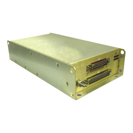
Audio International, Inc. PA-9075-101-x Installation Manual Specifications Physical Specifications – PA-9075-101-x Weight Approx. 2.02 lb / 0.92 kg 9.3" x 4.9" x 2.0" Dimensions (l x w x h) 24 cm x 12 cm x 5.1 cm Reference Drawings The following diagrams show the unit dimensions, mounting locations, and connector locations for the PA-9075-101-x. - Page 14 Audio International, Inc. PA-9075-101-x Installation Manual Document # 540312, Rev IR, 07/2005 Page 13 of 13...
Need help?
Do you have a question about the PA-9075-101-1 and is the answer not in the manual?
Questions and answers