LG WM3997H*A Service Manual
Hide thumbs
Also See for WM3997H*A:
- Owner's manual (80 pages) ,
- Owner's manual (80 pages) ,
- Owner's manual (80 pages)

Related Manuals for LG WM3997H*A


Summary of Contents for LG WM3997H*A
-
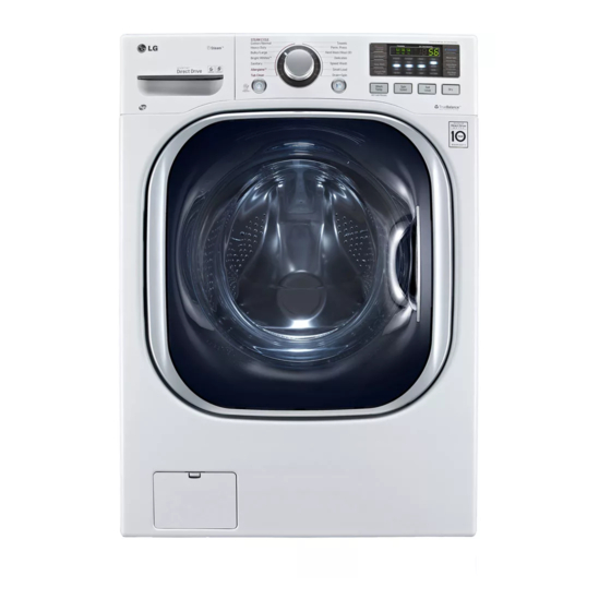
Page 1: Washing Machine
Website:http://biz.lgservice.com WASHING MACHINE SERVICE MANUAL CAUTION READ THIS MANUAL CAREFULLY TO DIAGNOSE PROBLEMS CORRECTLY BEFORE SERVICING THE UNIT. MODEL :WM3997H*A... - Page 2 JULY 2012 PRINTED IN KOREA MFL67307985...
- Page 3 CONTENTS...
- Page 4 WM3997H*A WARNING: Wash hands after handling...
-
Page 5: Features & Technical Explanation
2. FEATURES & TECHNICAL EXPLANATION 2-1. FEATURES Ultra Capacity The larger drum enables not just higher head drop and stronger centrifugal force, but also less tangling and wrinkling of the laundry. Heavier loads, such as king size comforters, blankets, and curtains, can be washed. Direct Drive System The advanced brushless DC motor directly drives the drum without belt and pulley. -
Page 6: Neuro Fuzzy Washing Time Optimization
2-2. NEURO FUZZY WASHING TIME OPTIMIZATION To get the best washing performance, optimal time is determined by the water temperature, the selected washing temperature, and the size of the load. water temperature washing time the best selected NEURO- washing rinsing time washing FUZZY temperature... -
Page 7: Child Lock
2-5. THE DOOR CAN NOT BE OPENED While program is operating. When a power failed and power plug is taken out in operation. While Door Lock lights turn on. White the motor is in the process of inertial rotating, through the operation is paused. 2-6. -
Page 8: Parts Identification
3. PARTS IDENTIFICATION Accessories... -
Page 9: Installation And Test
4. INSTALLATION & TEST Before servicing, ask the customer what the trouble is. When installing or repairing the washer, put on long gloves and safety glasses. Check the setup (power supply is 120 V , remove the transit bolts, level the washer, etc.) Check with the troubleshooting guide. -
Page 10: How To Connect The Inlet Hose
HOW TO CONNECT THE INLET HOSE Verify that the rubber washer is inside of the Cold valve connector. Tighten the inlet hose securely to prevent leaks. Install the inlet hose to correct temperature water tap. Otherwise, it cause drips on the drawer panel handle and drawer panel. -
Page 11: Test Operation
7 TEST OPERATION Preparation for Press the POWER button. Press the START/PAUSE washing. button. • Connect the power plug to the outlet. • Listen for a click to determine if the • Connect the inlet hoses. door has locked. Check the water heating Check the automatic reverse Check the water supply. - Page 12 ■ F2004RDT...
- Page 14 ime Delay DRY SELECTOR RINSE/ SPIN/ TEMP. Button...
-
Page 16: Test Mode
7. TEST MODE SPIN SPEED SOIL LEVEL WASH/RINSE DELAY WASH... -
Page 17: Troubleshooting
8. TROUBLESHOOTING... - Page 18 • The connector (3-pin, male, white) in the MOTOR LOCKED MOTOR HARNESS is not connected to the connector (3-pin, ERROR female, white) of STATOR ASSEMBLY. • The electric contact between the connectors (3-pin, male, white) in the MOTOR HARNESS and 4-pin, female, white connector in the MAIN PWB ASSEMBLY is bad or unstable.
-
Page 19: Fault Diagnosis And Troubleshooting
8-3. FAULT DIAGNOSIS AND TROUBLESHOOTING CAUTION 1. Be careful of electric shock if disconnecting parts while troubleshooting. 2. First of all, check the connection of each electrical terminal with the wiring diagram. 3. If you replace the MAIN PWB ASSEMBLY, reinsert the connectors correctly. NO POWER Check the fuse or reset Is the supplied voltage 220V AC? - Page 21 If it still has severe vibration and noise, regulate a specific spin speed that generates excessive vibration and noise as follows: 1) Put an unbalance part (rubber) inside of the drum. 2) Start the QC test mode (Refer to section 7-2). 3) Press Delay Wash button, then ‘...
- Page 22 Steam Steam...
- Page 23 Softener...
-
Page 24: Heating Without Water
HEATING WITHOUT WATER DRAIN MALFUNCTION... - Page 25 WASH HEATER TROUBLE HEATING CONTINUOUSLY ABOVE THE SETTING WATER TEMPERATURE...
-
Page 26: Will Not Circulate Water
WILL NOT CIRCULATE WATER... -
Page 27: Spin Trouble
SPIN TROUBLE... - Page 28 Replace the thermistor. Is the resistance of thermistors on dry duct 6322FR2046C : Dry 2.5k - 180k (at 100 Duct Disassemble the cabinet cover and condensing bellows. Clean the bellows Is there any foreign object in the condensing bellows. Disassemble the dry fan assembly and dry duct upper, and remove foreign objects in duct and fan.
-
Page 30: Control Panel
DISASSEMBLY INSTRUCTIONS Be sure to unplug the machine before disassembling and repairing the parts. CONTROL PANEL 1 Unscrew 2 screws on the back of the top plate. TOP PLATE ASSEMBLY 2 Pull the top plate backward and upward as shown. 3 Disconnect the Display PWB assembly connector from the cabling. - Page 31 MAIN PWB ASSEMBLY Disconnect the POWER connector and the pressure switch assembly. Remove the protective cover. PROTECT COVER Disconnect the connectors. Unscrew 1 screw on the back. Remove the main PWB.
- Page 33 Open the door. Unscrew the 7 screws from the HINGE COVER. Put a flat ( - ) screwdriver into the openng of the hinge, and pull out the hinge cover. Unscrew a screw from the lower side of door. Disassemble the door upward. Be careful! The door is heavy.
- Page 34 CABINET COVER Unscrew the 5 screws from upper of the cabinet cover. Unscrew the screw from the filter cover. Put a flat ( - ) screwdriver or putty knife into the hinge slots at the bottom of the cover and pry it out.
- Page 35 Open the door. Disassemble the clamp assembly. Tilt the cabinet cover. Disconnect the door switch connector. NOTE : When assembling the cabinet cover, connect the door switch connector. Lift and separate the cabinet cover. Disassemble the clamp assembly. Disassemble the gasket.
-
Page 36: Door Lock Switch Assembly
DOOR Open the door. Unscrew the 4 screws from the hinge. (Use the 8mm tool.) Disassemble the door upward. DOOR LOCK SWITCH ASSEMBLY Open the door and remove the gasket using the special gasket pliers. Unscrew the 2 screws. NOTE •... - Page 37 PUMP Disassemble the cabinet cover. CIRCULATION Separate the pump hose, the bellows, the HOSE circulation hose assembly from the pump PUMP HOSE assembly. BELLOWS Disassemble the pump assembly. HEATER Disassemble the cabinet cover. Separate 2 connectors from the heater. Loosen the nut and pull out the heater. CAUTION •...
-
Page 38: Lamp Assembly
WHEN FOREIGN OBJECT IS STUCK BETWEEN DRUM AND TUB Disassemble the cabinet cover. Separate the heater from the tub. Remove any foreign objects (wire, coin, etc.) by inserting a long bar in the opening. LAMP ASSEMBLY Unscrew 2 screws on the back of the top plate. TOP PLATE ASSEMBLY Pull the top plate backward and upward as shown. - Page 39 MOTOR/DAMPER Disassemble the back cover. Rotor Remove the bolt. Pull out the rotor. Bolt Unscrew the 2 screws from the tub bracket. Remove the 6 bolts on the stator. Unplug the 2 connectors from the stator. Disassemble the damper hinges from the tub DAMPER HINGE, and base.
-
Page 40: Exploded View
EXPLODED VIEW 8-1. CABINET & CONTROL PANEL ASSEMBLY 부 분해도 M410 F215 A175 A485 F210 F110 A455 A450 A106 A104 A105 A102 A111 A110 A410 A103 A150 A152 A181 A180 A154 A101 A156 A141 A390 A153 A151 A100 A131 A130 A430 A140 A133... - Page 41 EXPLODED VIEW 8- . R M & T B ASSEMBLY K350 K143 K123 K361 K360 K610 F140 K411 K611 K115 K410 K141 K110 K111 K117 K140 F310 F315 K571 K142 F465 K190 K572 F464 F463 K513 K570 K516 K511 K122 K130 K125 K320...
- Page 42 EXPLODED VIEW 8- . ISPENSER ASSEMBLY F322 F323 F462 F321 Inlet Valve Filter SVC F300 F180 COLD (BLUE) HOT (ORANGE) F170 F160 F340 F227 F226 F329 F327 F225 F430 F220 F441 F120 F130 F432...
- Page 43 EXPLODED VIEW M111 M110 M121 M100 M210 M235 M120 M240 K311 M130 M215 M101 M220 M312 K311 M310 M311 M230...
Need help?
Do you have a question about the WM3997H*A and is the answer not in the manual?
Questions and answers