
Related Manuals for Holman Ultra-Max UM1854Q-NAT


Summary of Contents for Holman Ultra-Max UM1854Q-NAT
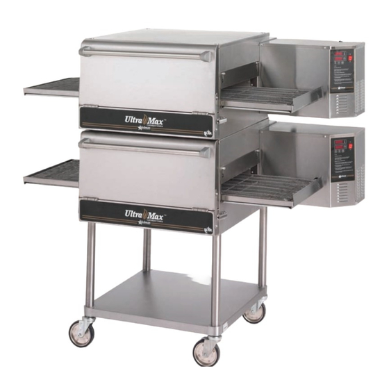
- Page 1 ® CONVEYOR OVEN MODEL UM1854-NAT/-LP UM1854Q-NAT/-LP UM1854-NATX/-LPX Installation and Operation Instructions 2M-Z5649 Rev. L 10/20/2010 UM1854...
-
Page 2: Safety Symbol
SAFETY SYMBOL These symbols are intended to alert the user to the presence of important operating and maintenance instructions in the manual accompanying the appliance. RETAIN THIS MANUAL FOR FUTURE REFERENCE NOTICE Using any part other than genuine Star factory supplied parts relieves the manufacturer of all liability. -
Page 3: Specifications
SPECIFICATIONS UM1854-NAT, UM1854-LP Gas Rating/Connection: 40,000 BTU/hr (10080 kCal/min)(703kW) 1/2" NPT male pipe connection Gas Supply Pressure: Natural - 5-6" water column (15-30 mBar) Propane - 11-12" water column (27.5-30 mBar) Electrical Supply: Separate 15 Amp 110VAC, single phase, 50/60 Hz service per Oven Approximate Weight (Single Oven with Cart): Installed - 280 Lbs (127.27 kg), Shipping - 350 Lbs (159.09 kg) Dimensions: Width: 60.6" (153.9 cm) Depth: 39.9" (99.82 cm) - Front Door(s) Closed 51.3" (130.3 cm) - Front Door(s) Open Height: 43.3" (110.0 cm) - Single Oven with Stand 60.6" (153.9 cm) - Double Oven with Stand 62.8" (159.5 cm) - Triple Oven with Dolly Recommended Minimum Clearances: Rear of Oven to Wall 0" (0 cm) Conveyor Extensions to Wall 6" (15.2 cm) ... -
Page 4: General Information
GENERAL INFORMATION This equipment is designed and sold for commercial use only by personnel trained and experienced in its operation and is not sold for consumer use in and around the home nor for use directly by the general public in food service locations. First and foremost, each crate should be examined before signing the Bill of Lading to report any visible damage by the trucker in transit and to account for the proper number of crates. If there is apparent damage, arrangements should be made to file a claim against the carrier. Interstate Commerce Regulations require that the claim must be initiated by the consignee. Proper and secure storage facilities should be arranged for the oven(s) if necessary to protect it from outdoor or damp conditions at all times before installation. -IMPORTANT- When you have all the crates unloaded, open the crates and remove all plastic covers. Inspect at once for concealed damage. If anything appears to be damaged, contact the appropriate persons immediately to file a damage claim. -
Page 5: Purchaser's Responsibility
PURCHASER'S RESPONSIBILITY It is the responsibility of the purchaser: 1. To see that the gas and electric services for the oven are installed on site in accordance with the manufacturer's specifications. 2. To unload, uncrate, and install the oven in its proper location and in accordance with this installation operation manual. 3. To see that all gas and electric services are connected properly by a qualified installer of your choice. All such connections must be in accordance with applicable code requirements. 4. To arrange for inspection and operation check-out by an authorized service technician. The warranty becomes effective upon verification of proper installation. IMPORTANT SAFETY INFORMATION Do not attempt to operate the oven until connection of utility service has been fully inspected by an authorized service technician or a Star Service Representative. This service is required by Star in order... -
Page 6: Installation Information
INSTALLATION INFORMATION THE INSTALLATION INSTRUCTIONS CONTAINED HEREIN ARE FOR THE USE OF QUALIFIED INSTALLATION A ND SERVICE PERSONNEL ONLY. INSTALLATION OR SERVICE BY OTHER THAN QUALIFIED PERSONNEL MAY RESULT IN DAMAGE TO THE OVEN AND/OR INJURY TO THE OPERATOR. Qualified installation personnel are individuals, a firm, a corporation, or a company which either in person or through a representative are engaged in and responsible for: 1. The installation or replacement of gas piping and the connection, installation, repair, or servicing of equipment. 2. The installation of electrical wiring from the electric meter, main control box, or service outlet to the electric appliance. Qualified installation personnel must be experienced in such work, familiar with all precautions required, and have complied with all requirements of state or local authorities having jurisdiction. -
Page 7: Smoke Candle Test
VENTILATION A VENT IS REQUIRED: Local codes prevail. These are the "authority having jurisdiction" as stated by the National Fire Protection Association, Inc. in NFPA 96-Latest Edition. For further ventilation information see below. A ventilation hood is required to remove heat and cooking odors. For gas ovens, a ventilation hood is also required to remove the products of combustion. The hood and HVAC installation must meet local codes to gain approval by the authority having jurisdiction. Requirements may vary throughout the country depending on the location by city, county, and state. Obtain information from the authority having jurisdiction to determine the requirements for your installation. Obtain information and review copies of codes or documents that will be used to inspect and approve your installation. Your ventilation hood supplier and HVAC contractor should be contacted to provide guidance. A properly engineered and installed ventilation hood and HVAC system will expedite approval and reduce oven maintenance costs. -
Page 8: Access Considerations
GAS SUPPLY RATING AND SIZING Calculations for pipe sizing must take into account the maximum usage rate of all other appliances in the kitchen or one or more of the appliances will suffer from inadequate or dangerous performance. The 1/2" NPT connection for the oven is generously sized for use in the control box of the oven. However, unless the oven installation is within 10 feet of the main building gas supply, the supply must be larger. For each oven, a 3/4" NPT flexible quick connect hose and full port gas shut-off valve is recommended as a MINIMUM. The main pipe supplying each oven branch may need to be larger depending on the number of appliances serviced, the number of elbows in the piping, and the pressure. This should be sized and installed by a professional familiar with any local codes that may also affect the installation. ACCESS CONSIDERATIONS Locating the gas valve(s), quick connect hose(s) and electrical outlet(s) at the control box end of the oven will allow easier access for any service visits. This improved access should make any necessary service quicker resulting in less kitchen disruption. It will also allow easier disconnection of electricity, gas, and restraints for cleaning around and behind the oven. ELECTRICAL CONNECTION Before making any electrical connections to this unit, check that the power supply is adequate for the voltage, amperage, and phase requirements stated on the rating plate. A wiring diagram is included herewith. When installed, this appliance must be electrically grounded and its installation must comply with the National Electric Code, ANSI-NFPA 70, latest version, manufacturer's installation instructions, and applicable local municipal building codes. In Canada, all electrical connections are to be in accordance with CSA C22.1 - Canadian Electrical Code Part 1 and/or local codes. -
Page 9: Stacking Instructions
WARNING: To prevent damage to the control valve regulator during the initial turn-on of gas, it is very important to open the manual shut-off valve very slowly. After the initial gas turn-on, the manual shut-off valve must remain open except during pressure testing as outlined in the above steps or when necessary during service maintenance. STACKING INSTRUCTIONS The following instructions should be followed when stacking more than one unit. Single Oven (or Bottom) Cart Install: 1. Remove door, conveyor, and finger assemblies. 2. Unbolt unit from shipping crate (2 bolts). 3. Turn unit on front as shown. 4. Slide legs into stand shelf and thread legs into bottom of oven. 5. Install casters into bottom of legs. Place casters with brakes to the front. 6. Position shelf as desired and fasten to legs. -
Page 10: Restraint Requirement
HOLLOW WALL STUD OR MASONRY WALL RESTRAINT REQUIREMENT 1. The installation shall be made with a gas connector that CAUTION complies with local codes for connectors for movable DO NOT WORK AROUND THE CONVEYOR gas appliances and a quick-disconnect device that BELT WITH LONG HAIR, LOOSE CLOTHING, complies with local codes for such devices in use OR DANGLING JEWELRY. GETTING with gas fuel. CAUGHT IN THE BELT COULD RESULT IN 2. The installation of the restraint must limit the movement DISMEMBERMENT OR FATAL INJURY. of the oven(s) without depending on the connector, the quick disconnect device, or associated piping to limit the oven movement. Unless specified otherwise, conveyor travel is factory set for left to right operation when facing the front of the 3. If the restraint must be disconnected during oven. If a direction change is required, refer to "DISPLAY... -
Page 11: Safety Tips
To adjust the time and temperature: Please take time to read the following safety operating instructions. They are the key to the 1. Press the DOWN and UP arrows ( ) at successful operation of your Ultra-Max Conveyor the same time. Hold for four seconds until the Oven. TIME display goes blank. 2. Press the ENTER button ( ) to switch between SAFETY TIPS TIME and TEMPERATURE. 3. Press the UP arrow ( ) to increase or the DOWN arrow ( ) to decrease the TIME or For your safety, read before operating. -
Page 12: Display Information
DISPLAY INFORMATION ADDITIONAL FUNCTIONS The conveyor belt direction and the temperature display can When operating the oven, there are different be changed on the conveyor oven by a qualified technician. levels of access: To change the belt direction, the technician must reverse the 1. Store Level - General employees would know motor direction and rotate the conveyor belt for proper oven these functions and how to change them. While function. A technician can also change the temperature display from Fahrenheit to Celsius. These changes can be made by the oven is running, enter this mode by holding the the technician during the start-up/check-out or at a later date. DOWN and UP arrows ( ) simultaneously for four seconds. The TIME display goes blank and the ERROR CODES TEMP setpoint is displayed. Adjust with the DOWN... -
Page 13: Conveyor Speed
BAKE TIME VERSUS TEMPERATURE CONVEYOR SPEED Bake Time (Conveyor Speed) - As stated previously, bake 1. Bake time is actually conveyor speed and is defined time (conveyor speed) is defined as the amount of time as the time the product is actually in the oven. This is elapsed between the time the leading edge of the product measured by noting the time when the leading edge of enters the oven and the leading edge of the product exits the product enters the oven and the time the leading the oven. Bake time is controlled by adjusting the digital edge of the product leaves the oven. This is adjusted speed controller. The setting on the control panel indicates by using the conveyor speed controller. the actual bake time. 2. Bake temperature is adjusted by changing the setpoint Bake time will be the same for any size product. of the temperature controller to the desired bake temperature. When the oven reaches the desired TIME OF DELIVERY temperature, the red dot in the lower right corner of the... -
Page 14: Maintenance Instructions
MAINTENANCE INSTRUCTIONS DISCONNECT THE POWER SUPPLY BEFORE SERVICING OR CLEANING THIS OVEN. SAFEGUARD THE POWER SO IT CANNOT BE A CCIDENTALLY RESTORED. FAILURE TO DO SO COULD RESULT IN DISMEMBERMENT, ELECTROCUTION, WARNING OR FATAL INJURY. THERE IS MORE THAN ONE POWER SUPPLY CONNECTION POINT WHEN OVENS ARE STACKED, SO MAKE SURE THAT ALL SWITCHES ARE IN THE OFF POSITION BEFORE CLEANING OR MAINTENANCE. No electrical components should be subjected to moisture. It is therefore important that the oven is wiped down carefully. NEVER throw buckets of water over the oven or subject it to pressure washing from a hose or a pressure spray. If water or other liquid is spilled on the oven, make sure that none of it has entered the control box area before switching the oven ON. If in doubt, call your service company. Adhere to the following warnings when cleaning or maintaining your gas conveyor oven: 1. The oven must be cool. Do not use power cleaning equipment, steel wool, or wire brushes on stainless steel surfaces. CAUTION 2. Do not use a caustic or an alkaline base cleaner on the interior of the oven. This will ruin the aluminized finish of the oven interior. - Page 15 DIRECTIONS FOR DISASSEMBLY 1. Remove crumb trays and 2. Push the spring-loaded coupling 3. Lift up the left end of the conveyor shelves from both ends. in to disengage the pin in the frame so the crumb tray supports shaft. Rotate the shaft so the pin clear the tunnel opening. Push will not go back in the coupling the conveyor frame through the slots. tunnel opening. 6. Upper nozzle (with slot) and 4. Finish removing the conveyor 5. Upper finger assembly can be assembly from the right end of removed complete or the small columnating plates (with tab).
-
Page 16: Conveyor Belt Tension
CONVEYOR BELT TENSION The conveyor belt of the Ultra-Max Gas Conveyor Oven does not have a tension adjustment. If the belt becomes too loose, a link will have to be removed to tighten. A belt that is too tight will also cause operational problems due to excessive drag. We suggest that you have a qualified service technician perform this adjustment. CAUTION Careful consideration should be exercised prior to removing a belt link because a belt that is too tight will impede the smooth operation of the conveyor. Remove the outside master links on the right and left sides of the conveyor belt. Remove the center splice clips next. CONVEYOR BELT LINK REMOVAL An entire link can be removed with the conveyor assembly either in or out of the oven. This may be necessary as the belt stretches after continuous use. Following are the necessary steps for removing links: 1. Move the splice clips to either end of the oven for easy access. 2. Unhook the splice clips using long nose pliers. - Page 17 Visit our Website at: www.star-mfg.com Email: service@star-mfg.com THOROUGHLY INSPECT YOUR UNIT ON ARRIVAL This unit has been tested for proper operation before leaving our plant to insure delivery of your unit in perfect condition. However, there are instances in which the unit may be damaged in transit. In the event you discover any type of damage to your product upon receipt, you must immediately contact the transportation company who delivered the item to you and initiate your claim with same.
- Page 18 DSIC 34 23 26 37 26 37 THS 2 120V M.V. 3 SENSE 4 38 25 PLUG ON BACK OF MOTOR IS SHOWN ROTATED 180° SECOND GENERATION CN5 TO SMALL MOTOR 7 = SPEED (GRD) 6 = SPEED SIGNAL 5 = SPEED (5V REF) 4 = (NOT USED) 3 = TACH (GND) 2 = TACH (+5V)
- Page 19 GM/C - GEARMOTOR & CONTROLLER - CAPACITOR, CIRC FAN MOTOR DSIC - DIRECT SPARK IGNITION CONTROLLER - POWER SUPPLY, 24VDC 150W PS - MOTOR, CIRC FAN - OVEN CONTROL BOARD - COOL DOWN T-STAT - CONTROL BOX TEMP LIMIT (MAN RESET) - COOK CHAMBER TEMP LIMIT (BULB &...
-
Page 21: Parts List
PARTS LIST November 22, 2010, Rev. L Ultra-Max Gas Conveyor Oven UM1854-NAT/LP CONTROL BOX Fig No Part No Description Application G9-GC0013 CONTROL BOX DOOR PS-Z7718 TIME & TEMP CONTROLLER GAS OVEN 120V G9-Z5250 POWER SUPPLY BRACKET G9-Z5251 GEARMOTOR BRACKET G9-Z5249 CONTROL BOX LID 2T-Z5175 THERMOSTAT, COOL DOWN, 120°F 2T-Z5176 THERMOSTAT, HI-LIMIT, 140°F 2T-Z5177 HIGH TEMPERATURE LIMIT 2E-Z5206... - Page 23 PARTS LIST September 20, 2010, Rev. L Ultra-Max Gas Conveyor Oven UM1854-NAT/LP MAIN ASSEMBLY Fig No Part No Description Application 2C-Z3780 CONDUIT RETAINER 2R-Z5188 LATCH KEEPER 2R-Z5174 LATCH G9-Z5309 DOOR BRACE 2P-09-WB-0003 PLUG CAP 2V-Z5293 HANDLE TUBE 2R-Z5279 HANDLE SUPPORT (PAIR) 2P-Z5303 HANDLE INSERT PLUG G9-GC0024 CONVEYOR WELDMENT 2A-Z6538 Serial Number COG450107B0011 or after DRIVE SHAFT ASSEMBLY W/ SPROCKETS 2A-Z6539 Serial Numbers before: COG450107B0011...
- Page 25 PARTS LIST September 20, 2010, Rev. L Ultra-Max Gas Conveyor Oven UM1854-NAT/LP FINGER ASSEMBLY Fig No Part No Description Application G9-Z5516 LOWER FINGER BAFFLE G9-GC0037 LOWER FINGER DIVERTER ASSEMBLY G9-GC0035 LOWER FINGER WELDMENT G9-GC0043 LOWER COLUMNATING PLATE G9-Z5432 LOWER-FULL NOZZLE, PLATE G9-Z5433 UPPER-FULL NOZZLE, PLATE G9-GC0055 UPPER COLUMNATING PLATE ASSY G9-GC0044 FINGER, UPPER - ASSY IMPORTANT: WHEN ORDERING, SPECIFY VOLTAGE OR TYPE GAS DESIRED...
Need help?
Do you have a question about the Ultra-Max UM1854Q-NAT and is the answer not in the manual?
Questions and answers