Table of Contents
Advertisement
Add.: 8 Gande Road, Tahui, Shihudang Town,
Songjiang District, Shanghai 201600, China
Tel.: 0086-021-57844525
Http://www.chziri.com
Manufacturer: Wenzhou Ziri Electrical
Technology Co.,Ltd.
Add.: Santiaoqiao Industrial Zone, Xiangyang
Town, Yueqing City 325604, Zhejiang, China
Tel: +86-577-27871155
User's Manual for
User's Manual for
ZVF9V-G/P Vector Inverter
ZVF9V-G/P Vector Inverter
Advertisement
Table of Contents

Related Manuals for Chziri ZVF9V-G/P


Summary of Contents for Chziri ZVF9V-G/P
- Page 1 User's Manual for User's Manual for ZVF9V-G/P Vector Inverter ZVF9V-G/P Vector Inverter Add.: 8 Gande Road, Tahui, Shihudang Town, Manufacturer: Wenzhou Ziri Electrical Songjiang District, Shanghai 201600, China Technology Co.,Ltd. Tel.: 0086-021-57844525 Add.: Santiaoqiao Industrial Zone, Xiangyang Http://www.chziri.com Town, Yueqing City 325604, Zhejiang, China...
- Page 2 Foreword Thank you very much for your purchase of the inverter ZVF9V series. This manual introduces the installation, operation, function setting, trouble shooting and etc. of the inverter ZVF9V series.. Incorrect installation or use may result in damage or other Publication Notes accidents.
- Page 3 Table of Contents Table of Contents Table of Contents Table of Contents Table of Contents Table of Contents Table of Contents Table of Contents Chapter 1 Safety Instruction Chapter 1 Safety Instruction ..........P1 ..........P1 Chapter 5 Operation of the Inverter ...........P50 Chapter 5 Operation of the Inverter ...........P50 1.1 Safety Symbols and Definitions ..........P1 1.1 Safety Symbols and Definitions ..........P1...
- Page 4 Chapter 1 Safety Instructions Chapter 1 Safety Instructions 1.2 Application Range Chapter 1 Safety Instructions This inverter is applicable to general industrial purpose three- phase AC asynchronic electric motor. 1.1 Safety Symbols and Definitions CAUTION The safety instructions described in this manual are very important. To avoid any error that may result in damage to equipment, injury to personnel or loss of property, do read and clearly understand all of the safety symbols, symbol definitions and be sure to observe the indicated safety instructions...
- Page 5 Chapter 1 Safety Instructions Chapter 1 Safety Instructions Be sure to install the inverter on metallic materials (i.e., metal). Proper Inverter Otherwise, there is the danger of fire. Inverter Inverter grounding Be sure not to let the foreign matter enter the inverter, such as wire method clippings, spatter from welding, metal (zinc or ferrous) meshavings and etc.
- Page 6 Chapter 1 Safety Instructions Chapter 1 Safety Instructions It is not advisable to install an electromagnetic contactor in the side of output power supply, because the operation of open and close to the contactor when the motor is running may cause damage to the inverter If the inverter runs at a frequency higher than 50Hz, DO confirm arising from over-voltage produced during this process.
- Page 7 Chapter 1 Safety Instructions Chapter 1 Safety Instructions Three-phase AC Power Supply Motor insulation should be checked before the inverter is used for the first use or reused after a long-term idle. Be sure the Inverter insulation resistance measured is no lower than 5MÙ. If the inverter is used beyond the range of allowable working voltage, then an extra step-up or step-down voltage transformer shall be configured.
- Page 8 Integration Module Schism Module...
- Page 9 Chapter II Introduction to the Product Chapter II Introduction to the Product Figure 2-5 Model B Outside Drawing Figure 2-7 Model C Outside Drawing 1.Fan 2. Control Panel 3.Cabnet Body 4. Wiring Copper Bar 5.Power Terminal 6. Electrolytic Capacitor (ELCC) 7. Operator Panel 8. Cabinet Door 1.
- Page 10 Chapter II Introduction to the Product Chapter II Introduction to the Product 2.5 Models and Specifications Inverter Models Input Adaptive Rated Rated Motor (G Constant Torque Load) Output Voltage Input Table 2-1 Inverter Models and Specifications Power KW Current A Current (A) (P Fan or Pump Load) Inverter Models...
- Page 11 current Leap frequency, Jog function,counter, trace to rotating speed, instant shutdown restarting, Frequecny upper/lower limitation , acceleration/ deceleration mode regulating, frequency meter and voltmeter output, multiple speed/program operation, two-wire/three wire control, vibration frequency control, Multi-function input terminal selection, Failure auto reset and 485COM. Jog acceleration/deceleration time, 0.1~3600.0 can be set.
- Page 13 Chapter 3 Inverter Installation and Wiring Chapter 3 Inverter Installation and Wiring 3.2 Parts Dismantling and Installation 3.1.3 Installation Instructions 3.2.1 Dismantle the upper cover. 1 Dismantle the upper cover of the inverter Model A. Put a finger into the heave of the lower part of the inverter and press it (as shown in the figure 3-4 where the arrow points), stretch forward for 30~50mm (as shown in the figure 3-5), then raise upward to open the upper cover of the inverter.
- Page 14 Chapter 3 Inverter Installation and Wiring Chapter 3 Inverter Installation and Wiring Step 3. Plug the ground end of connecting wire provided in the optional components into the slot of jack panel (as shown in the figure 3-10). 3.2.2 Installation of the remote-controlled operator panel and connecting wire 1 Installation of the operator panel and connecting wire of the inverter Model A Step 1.
- Page 15 Chapter 3 Inverter Installation and Wiring Chapter 3 Inverter Installation and Wiring lug the grounding end of connecting wire into the slot of jack panel (as shown in the 2 Installation of the operator panel and connecting wire of the inverter Model B figure 3-14).
- Page 17 Chapter 3 Inverter Installation and Wiring Chapter 3 Inverter Installation and Wiring 3.3.2 Cautions for Wiring DO NOT connect AC power supply to the output terminals marked "U", "V" and "W". Otherwise, there will be damage to the inverter. DO NOT connect control terminals (except terminals marked "TA", "TB"...
- Page 18 Chapter 3 Inverter Installation and Wiring Chapter 3 Inverter Installation and Wiring 3.3.3 Instruction on Main Circuit Terminals 1 The main circuit terminals are shown as in the figure 3-18~3-23. Braking Connect resistance to ground Connect to ground Braking unit Connect to Connect to Three-phase 380V...
- Page 19 Chapter 3 Inverter Installation and Wiring Chapter 3 Inverter Installation and Wiring 2 Function Description Main Circuit Terminals Function Description Terminal Symbols Power supply input terminals connecting to three-phase 380V or 220V AC input power supply Power supply input terminals connecting to single-phase 220V AC input power supply Inverter output terminals connecting to three-phase AC motor Connect External braking resistance terminals connecting to both ends of the external...
- Page 20 Chapter 3 Inverter Installation and Wiring Chapter 3 Inverter Installation and Wiring 3.3.4 Description on Control Circuit Terminals 2 Description on Control Circuit Terminals 1 Control circuit terminals are shown in the figure 3-24 and 3-25 Table 3-2 Function Description on Control Circuit Terminals Terminal Types Function Description...
- Page 21 Inverter...
- Page 22 Chapter 3 Inverter Installation and Wiring Chapter 3 Inverter Installation and Wiring Table 3-3 Capacity of Break Switch & Section Area of Wire Main Circuit mm Break Control The circuit breaker has the function of over-current Inverter Models Switch (A) Wire (mm Input Wire Output Wire...
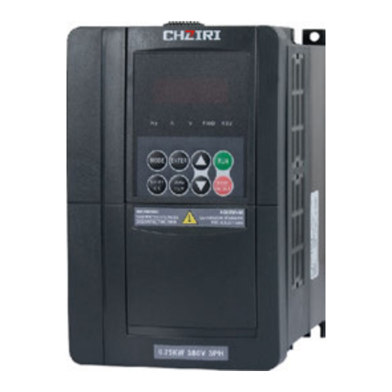
- Page 23 Chapter 4 Operator panel and its Operation Chapter 3 Inverter Installation and Wiring Main Circuit mm Break Control Chapter 4 Operator panel and its Operation Inverter Models Switch (A) Input Wire Wire (mm Output Wire 4.1 Operator Panel and Description The inverter ZVF9V series has 2 kinds of operator panels, with potentiometer or without potentiometer.
- Page 24 Chapter 4 Operator panel and its Operation Chapter 4 Operator panel and its Operation 4.1.2 Function Description on Keys Run key. When the operating instruction is to select operator panel control (F0.04=0), press this key and the inverter begins to run. LED display area Display frequency, current, parameters,...
- Page 25 Chapter 4 Operator panel and its Operation Chapter 4 Operator panel and its Operation 4.1.3 Function Description on Operator Panel Indicator Lights In any event, the operator panel will automatically return to Table 4-1 LED Status Description the Monitoring Mode if there is no key entry in 2 continuous minutes.
- Page 26 Chapter 4 Operator panel and its Operation Chapter 4 Operator panel and its Operation odification of parameter value for function codes (modify the parameter value for F0.01 4.1.5 Use of Operator Panel frequency setting mode from 1 to 0) Parameter modification in the monitoring status Initializing (modify the motor rotating speed from Fd00 to Fd04).
- Page 27 Chapter 4 Operator panel and its Operation Chapter 4 Operator panel and its Operation 4.2 Monitoring Parameter Display Display Category Name Unit Code Table 4-2 Monitoring Parameter LED Display List 0:OC-1 Acceleration running over current Deceleration running 1:OC-2 Category Display Code Unit Name over current...
- Page 28 Chapter 4 Operator panel and its Operation Chapter 5 Operation of Inverter 4.3 Failure Parameters Display Chapter 5 Operation of Inverter Table 4-3 Trouble Codes LCD Display List 5.1 Trial Operation 5.1.1 Safety Instructionon Trial Operation Category Failure Name Display Code Acceleration running over current Never open the front cover while the inverter is switched ON.
- Page 29 Chapter 5 Operation of Inverter Chapter 5 Operation of Inverter 5.2 Cautions for Operation 5.1.3 Trial Operation Try this step only after careful inspection as mentioned in the clause 5.1.2. While in trial operation, it is suggested that the motor has vacant load to avoid damage to this mechanical All the inverter functions are determined by set parameters.
- Page 30 Chapter 5 Operation of Inverter Chapter 5 Operation of Inverter 5.3 Examples of Use If the inverter is used beyond the range of allowable working voltage, then an extra step-up or step-down voltage transformer shall be This manual provides the following examples for users' reference on the use of configured.
- Page 31 Chapter 5 Operation of Inverter Chapter 5 Operation of Inverter 5.3.2Eg.2: Run or stop the inverter with external terminals, and feed the frequency 5.3.3 Eg.3: Run or stop the inverter with external terminals by adopting operation with external potentiometer. manner at multistage speed. Three-phase AC Power Three-phase...
- Page 32 Chapter 5 Operation of Inverter Chapter 5 Operation of Inverter 5.3.4Eg.4: Run or stop the inverter with external terminals, and feed the frequency 5.3.5 Eg.5: Multiple Inverter Ratio Interlocking Operation Control with external potentiometer and multiple motors run in parallel.. Three-phase Primary AC Power...
- Page 34 6.1 Schedule of Function Parameters 6.1 Schedule of Function Parameters 6.1.1 Basic Operation Functions Chapter 6 Description of Function Parameters Function Min. Default Name Setting Range Unit Unit Setting Code 6.1 Schedule of Function Parameters 0: Open vector control Control Mode Setting 1: V/F control 0: Set by the operator panel potentiometer.
- Page 35 6.1 Schedule of Function Parameters 6.1 Schedule of Function Parameters 6.1.1 F0 Series Basic Functions (Continued) 6.1.2 F1 Series Motor and Vector Control Parameters Function Min. Default Function Min. Default Name Setting Range Unit Setting Range Unit Setting Name Unit Code Unit Setting...
- Page 36 6.1 Schedule of Function Parameters 6.1 Schedule of Function Parameters 6.1.3 F2 Series Auxiliary Operating Parameters (Continuation ) 6.1.3 F2 Series Auxiliary Operation Parameters Function Min. Default Function Min. Default Setting Range Name Unit Name Setting Range Unit Setting Unit Code Code Unit...
- Page 37 6.1 Schedule of Function Parameters 6.1 Schedule of Function Parameters 6.1.4 F3 Series User Management Interface Parameters (Continuation ) 6.1.3 F2 Series Auxiliary Operating Parameters (Continuation ) Function Min. Default Setting Range Name Unit Function Min. Default Code Unit Setting Setting Range Name Unit...
- Page 38 6.1 Schedule of Function Parameters 6.1 Schedule of Function Parameters 6.1.5 F4 Series Switch Quantity Input/Output Parameters (Continuation...) 6.1.5 F4 Series Switch Quantity Input/Output Parameters (Continuation..) Function Function Min. Default Min. Default Setting Range Setting Range Name Unit Name Unit Unit Setting Unit...
- Page 39 6.1 Schedule of Function Parameters 6.1 Schedule of Function Parameters 6.1.6 F5 Series Analog Input/Output Parameters 6.1.6 F5 Series Analog Input/Output Parameters (Continuation...) Function Min. Default Setting Range Name Unit Function Min. Default Code Unit Setting Setting Range Name Unit Code Unit Setting...
- Page 40 6.1 Schedule of Function Parameters 6.1 Schedule of Function Parameters 6.1.6 F5 Series Analog Input/Output Parameters (Continuation...) 6.1.7 F6 Series PID Function Parameters Function Default Function Min. Min. Default Setting Range Name Setting Range Unit Name Unit Code Unit Setting Code Unit Setting...
- Page 41 6.1 Schedule of Function Parameters 6.1 Schedule of Function Parameters 6.1.7 F6 Series PID Function Parameters (Continuation...) 6.1.8 F7 Series Programmable Operation Parameters (Continuation..) Function Function Min. Default Min. Default Name Setting Range Setting Range Unit Name Unit Unit Setting Unit Setting Code...
- Page 42 6.1 Schedule of Function Parameters 6.1 Schedule of Function Parameters 6.1.8 F7 Series Programmable Operation Parameters (Continuation...) 6.1.9 F8 Series Communication Parameters Function Default Min. Function Default Min. Setting Range Name Unit Setting Range Name Unit Code Unit Setting Code Setting Unit Host address...
- Page 43 6.1 Schedule of Function Parameters 6.1 Schedule of Function Parameters 6.1.0F9 Series Protection Parameters 6.2 Detailed Description on Function Parameters F0 Series Basic Operation Parameters Function Min. Default Name Setting Range Unit Setting Code Unit F0.00 Control Mode Setting Setting Range: 0~1 Factory Default Setting: 1 Motor overload protection coefficient This function is used to select the inverter's control mode.
- Page 44 6.1 Schedule of Function Parameters 6.1 Schedule of Function Parameters Frequency path Frequency path Frequency path F0.01 Frequency setting mode selection Setting range: 0~8 Factory default setting: 1 Frequency setting path selection terminal 3 selection terminal 2 selection terminal 1 Keyboard potentiometer This function is used to select the operation frequency setting mode of the inverter.
- Page 45 6.1 Schedule of Function Parameters 6.1 Schedule of Function Parameters F0.02 Digital frequency control Setting range: 00~11 Factory default setting: 00 F0.04 Operation control mode selection Setting range: 0~2 Factory default setting: 0 This function is used to set the control mode for inverter's operation commands such LED unit digit as forwarding, reversing, jogging and stop.
- Page 46 6.1 Schedule of Function Parameters 6.1 Schedule of Function Parameters Torque lifting voltage changes as the rotator current changes. The larger the rotator current is, the larger voltage is lifted. If auto torque lifting is set, magnetic circuit saturation caused by overlarge F0.08 Basic operation frequency Setting range: 1.00~uppper limiting frequency lifting voltage when the motor has a light load can be prevented and overheat can e avoided when Factory default setting: 50.00Hz...
- Page 47 6.1 Schedule of Function Parameters 6.1 Schedule of Function Parameters This inverter series provide 4 groups of F0.13 Slip frequency compensation Setting range: 0.0~150.0% Factory default setting: 0.0% acceleration/deceleration time parameters. Others are defined in the parameter F2.22~F2.27 with default value of "1". Please During actual rotation, a motor's slip is influenced by variation in load torque, which select other groups of acceleration/deceleration time parameters causes deviation of actual speed from the expected value.
- Page 48 6.1 Schedule of Function Parameters 6.1 Schedule of Function Parameters Group F1 Motor and Vector Control Parameters F0.17 V/F frequency value F1 Setting range: 0.00~frequency value F2 Default setting: 12.50Hz F1.00 Motor rated voltage Setting range: 100~500V Default setting: as per spec. F0.18 V/F voltage value V1 Setting range: 0.0~voltage value V2 Default setting: 25.0% F1.01 Motor rated current Setting range: 0.1~500.0A Default setting: as per spec.
- Page 49 6.1 Schedule of Function Parameters 6.1 Schedule of Function Parameters This parameter is valid only when vector control is validated F1.10 Slip compensation coefficient Setting range: 0.50~2.00 Default setting: 1.00 (F0.00=0) and the operation mode is controlled by operator panel (F0.04=0) Proceeding vector control over no speed sensor, this parameter is used to adjust CAUTION...
- Page 50 6.1 Schedule of Function Parameters 6.1 Schedule of Function Parameters Group F2 Auxiliary Operation Parameters F2.03 Starting DC braking current Setting range: 0.0~100.0% Default setting: 0.0% F2.00 Starting mode selection Setting range: 0~1 Default setting: 0 F2.04 Starting DC braking time Setting range: 0.0~20.0S Default setting: 0.0S Starting DC braking current: This indicates the percentage of braking current during...
- Page 51 6.1 Schedule of Function Parameters 6.1 Schedule of Function Parameters F2.06 S curve initial stage time percentage Setting range: 10.0~40.0% F2.10 FRD/REV Dead Time Setting range: 0.0~10.0s Default value: 0.0s Default value: 20.0% 2.07 S curve rise/fall stage time percentage Setting range: 10.0~80.0% This indicates the interval between FRD and REV when the inverter transfers from Default value: 60.0% forward running to 0.00Hz then to reverse running;...
- Page 52 6.1 Schedule of Function Parameters 6.1 Schedule of Function Parameters F2.12Shutdown DC braking initial frequency Setting range:0.00~20.00 If the power off restart Function (restart after instantaneous power Hz Default value: 0.00Hz failure) is selected, it may cause unanticipated sudden restart once the power switches on, which may result in heavy loss of F2.13 Shutdown DC braking current Setting range: 0.0~100.0% Default value: 0.0% property, serious injury or death to personnel in some cases, eg.,...
- Page 53 6.1 Schedule of Function Parameters 6.1 Schedule of Function Parameters Jog operation begins if F2.00=0 and stops if F2.11=0 according F2.35 Remain to the starting mode. JOG control can be performed by the operator panel, control F2.36 Leap frequency 1 Setting range: 0.00~upper limiting frequency Default value: 0.00Hz terminals and COM ports.
- Page 54 6.1 Schedule of Function Parameters 6.1 Schedule of Function Parameters Group F3 User Management Interface Parameters F2.42 Carrier frequency Setting range: 1.0~15.0KHz Default value: as per spec. F3.00 LCD Language Selection Setting range: 0~1 Default value: 0 This function is used to set the carrier frequency of the inverter's output PWM wave and should be properly regulated.
- Page 55 6.1 Schedule of Function Parameters 6.1 Schedule of Function Parameters Group F4 On-off Input/Output Parameters F3.03 Remain F4.00 Selection of input terminal X1 Setting range: 0~30 Default value: 0 F3.04 Selection of monitoring parameter 1 Setting range: 0~18 Default value: 0 F4.01 Selection of input terminal X2 Setting range: 0~30 Default value: 0 F3.05 Selection of monitoring parameter 2 Setting range: 0~18 Default value: 1 F4.02 Selection of input terminal X3 Setting range: 0~30 Default value: 0...
- Page 56 6.1 Schedule of Function Parameters 6.1 Schedule of Function Parameters 17 Counter zero-clearance input 4 Acceleration/Deceleration time 1 5: Acceleration/Deceleration time 2 Once this function is set, connect this terminal with COM terminal and the counter It is used for external terminal's selection of acceleration/deceleration time, value will be "0".
- Page 57 6.1 Schedule of Function Parameters 6.1 Schedule of Function Parameters 2 Three-wire control mode 1 28 Inverter acceleration/deceleration disable command Three-wire control is shown in Fig.6-14, in which Xn stands for three-wire If this terminal is valid, the inverter will not be influenced by any external signals operation control terminal which can be (except the stop command) and remain running at current rotating speed.
- Page 58 6.1 Schedule of Function Parameters 6.1 Schedule of Function Parameters PLC multistage operation ends When a PLC multi-speed operating cycle is finished, a valid low power level 6 Lower limit of output frequency arrival pulse signal will be output at this port with signal width of 500ms. This refers to the indication signal output by the inverter when operation frequency reaches the lower limit of frequency.
- Page 59 6.1 Schedule of Function Parameters 6.1 Schedule of Function Parameters In Fig.6-15, Y1 is set to be a reset signal, Y2 is set to be a detection signal output, F4.15 is set to 8 and F4.16 is set to 5. F4.13 Overload Pre-alarm Level Setting range: 20~120% Default value: 100%...
- Page 60 6.1 Schedule of Function Parameters 6.1 Schedule of Function Parameters Group F5 Analog Input/Output Parameters Frequency Frequency F5.00 AVI input lower limit voltage Setting range: 0.0V~upper limit voltage Default value: 0.0V F5.01 AVI input upper limit voltage Setting range: Upper limit voltage~10.0V Default value: 10.0V F5.00 and F5.01 are applied to set the maximum and minimum values for external analog input voltage AVI, which should be set in accordance with actual situation of...
- Page 61 6.1 Schedule of Function Parameters 6.1 Schedule of Function Parameters Output voltage F5.15 Combined feed path setting Setting range: 000~666 Default value: 000 AFm:(0~AFM Upper limit value )=(0.00~ Maximum/Rated output voltage DFm:(0~DFM Upper limit value )=(0.00~ Maximum/Rated output voltage This parameter is used to set the frequency feed path. Bus bar voltage LED units digit: Operation figure 1 AFm:(0~AFM...
- Page 62 6.1 Schedule of Function Parameters 6.1 Schedule of Function Parameters Group F6 PID Function Parameters F5.15 Combined feed algorithm setting Setting range: 00~54 Default value: 00 F6.00 PID action setting Setting range: 00~11 Default value: 00 This function is used to set the combined feed algorithm. LED units digit algorithm 1 LED tens digit Algorithm 2 LED units digit: Function setting LED tens digit: PID input selection...
- Page 63 6.1 Schedule of Function Parameters 6.1 Schedule of Function Parameters 4: AVI setting F6.04 Feedback path gain Setting range: 0.01~10.00 Default value: 1.00 To set the target value by external voltage signal AVI (0~10V). 5: ACI setting If the feedback quantity is not in accord with the actual target value, then this parameter can be used to regulate the PID value till it is in accord with the request.
- Page 64 6.1 Schedule of Function Parameters 6.1 Schedule of Function Parameters Output F6.09 Sampling period T Setting range: 0.01~10.00s Default value: 0.00s frequency Sampling period refers to the cycle in which the system conducts sampling over Preset frequency feedback quantity. PID regulator calculation in each period of sampling and gets the output value of PID regulation.
- Page 65 6.1 Schedule of Function Parameters 6.1 Schedule of Function Parameters Group F7 Programmable Operation Parameters f1 f7 in this figure refers to the operation frequency at stage 1 7 separately. T1 T7 refers to the operation time at stage 1 7 separately. a1 a6 refers to acceleration time at stage 1 6 separately.
- Page 66 6.1 Schedule of Function Parameters 6.1 Schedule of Function Parameters F7.10 Multi-speed operation direction 2 Setting range: -000 ~ -111 Default value: -000 Multi-speed acceleration/deceleration time Current multi-speed frequency initial multi-speed frequency Basic operation frequency F7.09~F7.10 are used to set the direction for programmable multi-speed operation. acceleration/deceleration time 1 (F0.14, F0.15) Programmable multi-speed operation is always prior to external terminal control multistage speed.
- Page 67 6.1 Schedule of Function Parameters 6.1 Schedule of Function Parameters whether to save previous operation info for wobble start or not when the power is The actual wobble center is accumulated value of this parameter value and the switched on after power failure. If the store is valid, then the hundreds digit of setting frequency decided by external frequency setting path F0.01.
- Page 68 6.1 Schedule of Function Parameters 6.1 Schedule of Function Parameters Group F8 Communication Parameters F8.02 COM over time checkout time Setting range: 0.0~ 100.0s Default value: 10.0s F8.00 Local address Setting range: 0~31 Default value: 1 If correct data signal is not received by the local machine within/exceeding the interval defined by this parameter, then communication error will be judged by the This parameter is used to identify the local inverter's address which is unique when local machine.
- Page 69 6.1 Schedule of Function Parameters 6.1 Schedule of Function Parameters Group F9 Protection Parameters F9.01 Under-voltage protection level Setting range: 180~480V Default value: As per spec. F9.00 motor overload protection coefficient Setting range: 30~110% Default value: 105% This parameter stipulates the lower limit voltage allowed by DC bus bar when the inverter is in normal operation.
- Page 70 6.1 Schedule of Function Parameters 6.1 Schedule of Function Parameters Group FA Advanced Function Parameters FA.02 Energy consumption dynamic braking initial voltage Setting range 300~750V Default setting As per spec. FA.00Zero frequency operation threshold Setting range: 0.00~50.00Hz Default setting: 0.00Hz FA.03Energy consumption dynamic braking proportional action Setting range 10~100% Default setting As per spec.
- Page 71 Chapter 7 Common Problems, Anomalies and Troubleshooting Chapter 7 Common Problems, Anomalies and Troubleshooting Chapter 7 Common Problems, Error Probable Cause(s) Solution(s) Error Name Codes Anomalies and Troubleshooting Over voltage 7.1 Diagnostic Trouble Codes and Troubleshooting while at stop Table 7-1 Common Error Codes and Solutions Check if power supply voltage is Input power supply below below level.
- Page 72 Chapter 7 Common Problems, Anomalies and Troubleshooting Chapter 7 Common Problems, Anomalies and Troubleshooting 7.2 Anomalies and Solutions Error Probable Cause(s) Solution(s) Error Name Codes Table 7-2 Anomalies and Solutions Over torque lifting or Reduce torque lifting value improper V/F curve; or regulate V/F curve.
-
Page 73: Inspection And Maintenance
Chapter 8Inverter Inspection and Maintenance Chapter 8Inverter Inspection and Maintenance Chapter 8Inverter Inspection and Maintenance Make sure that only qualified personnel will perform maintenance, inspection and part replacement. 8.1 Inspection and Maintenance Wait at least 10 minutes after turning OFF the input power supply before performing maintenance or an inspection. - Page 74 Chapter 8Inverter Inspection and Maintenance Chapter 8Inverter Inspection and Maintenance 8.2 Replacement of Wearing Parts Contents of Inspection Inspection Criterias Inspection Items Method The wearing parts of inverter mainly include cooling fan and filter electrolytic capacitor. Usually, a cooling fan's service life is 20,000~30,000 hours and an electrolytic capacitor's Check if there is any big service life is 40,000~50,000 hours.
- Page 75 Chapter 8Inverter Inspection and Maintenance Chapter 9 Outline Dimension & Mounting Dimension Chapter 9 Outline Dimension & Mounting Dimension 8.3 Storage of Inverter Please pay attention to the following points if an inverter is set aside or stored for a short/long period: 9.1 Inverter Outline Dimensions &...
- Page 76 Chapter 9 Outline Dimension & Mounting Dimension Chapter 9 Outline Dimension & Mounting Dimension Dimension (mm) Dimension Gross Gross Inverter Models Figure Inverter Models Power Weight Power Figure Weight Figure Figure Figure Figure Figure Figure Fig.9-2 Inverter Model B Outline Dimensional Drawings...
- Page 77 Chapter 9 Outline Dimension & Mounting Dimension Chapter 9 Outline Dimension & Mounting Dimension 9.2 Operation Panel Outline Dimension and Mounting Hole Dimension Fig.9-3 Inverter Model C Outline Dimensional Drawings Dimension (mm) Gross Figure Inverter Models Power Weight Figure Fig.9-4 ZR04 Operator Panel Dimension Figure Extra mounting socket shall be assemblied when ZR04 operator panel is pulled out to install.
- Page 78 Chapter 9 Outline Dimension & Mounting Dimension Chapter 9 Outline Dimension & Mounting Dimension Fig.9-5 ZR05 Operator Panel Dimension Extra mounting socket shall be assemblied when ZR05 Fig.9-6 ZR Operator Panel Hold Dimension operator panel is pulled out to install. The hole dimension of the installation socket is as shown in Fig.9-6.
- Page 79 Chapter 10 Quality Warranty Appendix 1 Optional Parts Chapter 10 Quality Warranty Appendix 1 Optional Parts 1. Warranty Period under Normal Conditions All the optional parts can be ordered for with us if needed. We provide guarantees for repair, replacement and return of the purchase in 1 month from the date of use.
- Page 80 Appendix 1 Optional Parts Appendix 1 Optional Parts Table Appendix 1-1 Recommended Brake Assembly Matching Specifications 2.Remote-operated adapter and extended cable Braking unit Inverter Braking resistor There are two selections available for remote operation on the inverter ZVF9V series. If it is operated at short range 15m , just extend the shielding cable Resistor directly and connect it to the operator panel.
- Page 81 Appendix 2 EMI Prevention Appendix 2 EMI Prevention Appendix Table 1: Inverter System EMI Prevention Communication The electromagnetic environment is very complicated in industrial occasions. equipment Besides, the inverter's working principle also decides that EMI exists in the inverter itself. So it is very important to solve EMC problems effectively to Communication cable ensure reliable running of the system in such a comprehensive condition.
- Page 82 Appendix 2 EMI Prevention Appendix 2 EMI Prevention Other Inverter equipment wisted pair Motor Cable The electromagnetic field (EMF) caused by fundamental current has weaker effect on electric field coupling and magnetic flux inductive coupling of the parallel cable. While the EMF produced by the higher harmonic current has stronger effect on electric field coupling.
- Page 83 Appendix 2 EMI Prevention Appendix 2 EMI Prevention Attached Table II: Conventional Symbols Illustration Relay, contactor and other electromechanical elements Instantaneous current and voltage surge will be caused by the close and open of the switch devices such as relay, contactor and etc, which may result in discharging Name Figure Symbol Name...
- Page 84 Appendix 3 User Parameter Amendment Record Appendix 3 User Parameter Amendment Record Appendix 3 User Parameter Amendment Record Default Default Function Function Function Name Function Name Code Code Setting Setting Table Appendix 3-1 User Parameter Amendment Record Failure reset interval time Linear speed coefficient Function Default...
- Page 85 Appendix 4 User's Warranty Appendix 4 User's Warranty Default Default Function Function Function Name Function Name Code Code Setting Setting User's Details Multi-stage speed operating AFM gain setting direction 2 Remain Wobble operation parameter Name of Distributor Date of Purchase DFM gain setting Wobble preset frequency Remain...
- Page 86 Appendix 4 User's Warranty Inverter User's Warranty User's Details User's Work Unit Add. Post Code Contact Department Person Name of Add/Tel Distributor Date of Bill Number Purchase Inverter Identification Model(s) Number Name of Power Capability Equipment of the Motor Date of Date of Use Installation Description of Use...
Need help?
Do you have a question about the ZVF9V-G/P and is the answer not in the manual?
Questions and answers