
Related Manuals for Chziri ZVFG7 series


Summary of Contents for Chziri ZVFG7 series
- Page 1 I N V E R T E R ³ ¬ Ì © µ ç Æ ÷ INVERTER USER'S MANUAL ZVFG7 SERIES Ï µ Á Ð ZVFP7 Ï µ Á Ð SERIES É Ï º £ ³ ¬ Ì © µ ç Æ ÷ Ó Ð Ï Þ ¹ « Ë ¾...
- Page 2 Foreword Thank you very much for your purchase of ZVFG7 and ZVFP7 series of inverters. This manual introduces the installation, operation, function setting, trouble shooting and etc. of inverters. Incorrect installation or use may result in damage or other accidents. Do read all instructions in detail before installing or operating.
-
Page 3: Table Of Contents
Directory Directory Article 1. Article 6 Reference on Function Data Safety Instruction 6.1The fleet of function data 1.1 The indication of safty symbol 6.2Detail reference of function data 1.2 Caution of electric 1.3 Caution of Installation and connection item Article 7 Trouble diagnosis and treatment 58 1.4 Caution of Operation 1.5 Caution of enviroment 7.1Trouble and the reason... -
Page 4: Caution Of Electric
Article 1 Safety Instruction Indications of Safety Symbols Article 1 To use and operate the inverter correctly, do read and clearly understand the following symbols in this manual before installing and operating it, and follow the instructions exactly. Safety Instruction WARNING: This symbol calls your attention to avoid any incorrect operation that can result in serious damage to the... - Page 5 Article 1 Safety Instruction Article 1 Safety Instruction Cautions for Operation Cautions for operating ambient It is strongly recommended not to use the Be sure to turn ON the input power supply only after closing the case. While the inverter is energized, be sure not to open the case. Otherwise, there is the inverter in the following places that have: danger of electric shock.
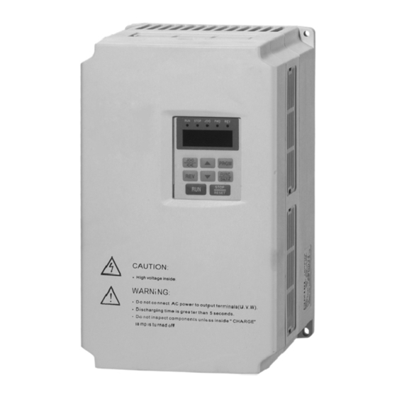
- Page 6 Article 2 Introduction to Products Checking after you got the Inverter Article 2 The Inverter has been inspected strictly and keep the Inverter shock resistent.crash resistent ,maybe the accident happened in the transport,so please open the carton and check it as soon as you got the Introduction to Products products.
- Page 7 Article 2 Introduction to Products Article 2 Introduction to Products Product Specifications Standard Technical Specifications Item Reference Type of Inverter Input Voltage Max Adapter Rated output Single phrase 200V +15% three phrase 400V+20% Three-phase 200V 15% Input voltage means type of fan Moter(kw) current(A) means type of...
-
Page 8: Caution Of Enviroment
Article 3 Installation and Connection Installation of Inverter Article 3 3.1.1 Caution of enviroment Under the 1000meters of altitude Temperature.humidity: Temperature:-10 degree ~+40 degree h umidity: Installation and Connection 20%~90%RH(with water drip) Without dirct sun shine.no water drip .no evapour.dust and oil place Indoor,avoid t he sunshin e,without dust ,without combustible and corrosion No granule of metal or foam of metal place Installation of Inverter... -
Page 9: Article 3 Installation And Connection
Article 3 Installation and Connection Article 3 Installation and Connection 3.2.2 Key electric connecting Inverter connecting Caution of the key electric conneting 3.2.1 Standard connecting diagram Dangerous: Be sure the key electirc connecting correct.Three-phase 200V or 400V input have to connect R.S.T terminal blocks, (single phrase 220V input have to connect the terminal block L1.L2), output have to connect the terminal block U.V.W, brakeing unit electric reactor... - Page 10 Article 3 Installation and Connection Article 3 Installation and Connection Main circuit terminal reference The key terminal Mark Title of terminal Function reference ZVFG7 2007S 2022S Connect the Three-phase Input terminal of Inverter R S T Connect the single phase earth single phrase input connecter brake resisitance Input terminal of Inverter...
- Page 11 Article 3 Installation and Connection Article 3 Installation and Connection 3.2.3 Connecting of the control circuit Reference for the terminal of control circuit Caution of the connecting circuit Type Mark Title of terminal Reference of function ----- Attention: Public terminal Control circuit must be absorb creen wire and twisted pair wire,and it must be connect to the key circuit .stav ing Positive rotata/stop...
- Page 12 Article 3 Installation and Connection 3.2.4Directory of complement electric Complement of circuit breaker.magnetic starter and the width of wire with the Inverter Max adapter K e y ci r c u i t C o n t r o l l in e Circuit breaker C o n t a c t o r T i t l e...
-
Page 13: Article 4 Control Panel And Display
Article4 Control panel and display Control panel Article4 4.1.1 Figure of panel Control panel(1) Control panel and display LED desplay Area LED display area Display freguency out put. STOP Display current status:run.stop. power.setted parameter crowl.positive.reverse Control panel inerease/introduce 4.1.1Figure of panel PRGM program crowl/remove... -
Page 14: Control Panel
Article4 Control panel and display Article4 Control panel and display 4.1.2 Illustration of key Control panel operation Illustration of panel 4.2.1 Method of the data modify Symbol Title Reference of function If you need to modify the data,first enter into the function code which will be modified,then reset the data,the process as following: Press it start run(If set F001 as the exterior control, Subsequence... - Page 15 Article4 Control panel and display Article4 Control panel and display 4.2.1 Example of the data modify No.2Example :Recovery the factory data(data initialize) Illustration Subsequence Operation No.1Example :Change output frequency 50HZ to 25HZ press FUNC Display F000,enter into the function setting. Illustration Subsequence Operation...
- Page 16 Article4 Control panel and display Content of display on the control panel Article 5 Inverter in the stand by status,when you press "Display"key,display cycle as follows. Run-in test Stand by or display display display run status C XXX U XXX d XXX H50.0 or P50.0 Run-in test...
-
Page 17: Article 5 Run-In Test
Article 5 Run-in test Article 5 Run-in test Run operate Run-in test 5.1.1 Caution of the safty before Run-in test 5.2.1 Cautions in runing status Dangerous: Install well the shell when it run,do not dismount the shell when it runs,avoid the electric shock. Dangerous: Install well the shell when it run,do not dismount the shell Attention:... - Page 18 Article6 Function parameter illustration Directory of function parameter Article6 Function of control Factory Function Range of set Title of function parameter Note code Function parameter illustration 0.0~max frequency(F004) F000 Run frequency 5.0Hz 0: panel control (positive start,reverse start,stop) 1: ExteriorTerminal control (positive Choice of F001 start/stop, reverse/stop)
- Page 19 Article6 Function parameter illustration Article6 Function parameter illustration Basic function(continous upstair) Multi speed run Factory Function Factory Function Range of setting Range of setting Title function parameter Note Title function parameter Note code code F038 Sixth speed up time 0.1~999.9S 10.0S F014 Toplimit frequency...
- Page 20 Article6 Function parameter illustration Article6 Function parameter illustration PID function Multi-speed run (Continous) Function Factory Function Factory Range of setting Range of setting Title function parameter Note Title function parameter Note code code F080 0 9999 Counter coefficient 0:PID function expiry F064 PID mode choice 1: PID validity expiry...
- Page 21 Article6 Function parameter illustration Article6 Function parameter illustration Multi terminal Multi terminal Function Factory Function Factory Range of setting Title function parameter Note Range of setting code Title function parameter Note code 0:Multi speed 1 0:OC- 1 overload current when F093 X1 function choice 1: Multi speed 2...
- Page 22 Article6 Function parameter illustration Article6 Function parameter illustration Function parameter specific instruction F002 Frequency Setting Way Choice Setting Range: 0~4 Factory Setting: 0 F002=0: Frequency is set by key on panel. Control Function F002=1: Frequency is set by potentiometer on panel. F000 Operation Frequency Setting Range: 0.0 ~ Top Frequency Factory Setting: 5.0HZ F002=2: Frequency is set by outer potentiometer or outer voltage DC 0~10V.
- Page 23 Article6 Function parameter illustration Article6 Function parameter illustration V/F Curve Setting Below are V/F Curve Type Generally Used V/F Curve Setting Value F004 Highest Frequency Setting Range: Lowest Frequency~400.0HZ Factory Setting:50.HZ Normal V/F Curve Settings Voltage Funct ion In struc tion: Such function is used to set the highest frequency of the Inverter's Function Code Parameter Value allowed output.
- Page 24 Article6 Function parameter illustration Article6 Function parameter illustration Basic Function F016 Start Frequency Setting Range: 0.0~10.0HZ Factory Setting: 1.0HZ F011 Analog input corresponding with highest frequency Setting Range: 0~100% Function Instruction: Such function is used to set the start frequency of the Inverter. Factory Setting: 100% Note: If this value is set too much, it is easily to occur jump fault.
- Page 25 Article6 Function parameter illustration Article6 Function parameter illustration Crawl Function Multi-Speed Operation In multi-speed operation, F000 is the operation frequency of the first sector, F018 When terminal has to lead out crawl function, X1~X4 multi-function terminal must is the acceleration time of the first sector, F019 engaged in operation as the deceleration have one of them choose out crawl (details are in function code F093~F096 function choice), otherwise this function is useless, and connection chosen terminal with COM time of the first sector.
- Page 26 Article6 Function parameter illustration Article6 Function parameter illustration Program Operation F025 Sector 2 Speed Frequency Setting Range: Bottom Frequency ~Top Frequency Factory Setting:5.0HZ In program operation, operation frequency, acceleration time and deceleration time F026 Sector 2 Speed Acceleration Time Setting Range:0.0~999.9S Factory is set by multi-sector speed function F025~F045, F000 participate operation as the Setting:10.0S...
- Page 27 Article6 Function parameter illustration Article6 Function parameter illustration PID Function F066 PID Feedback Way Choice Setting Range: 0~1 Factory Setting: 1 PID control is through detecting the measured out feedback value of the co ntrolled F066=0: Outer Voltage. objec t, com parin g with the set ta rget value, then adjust and control the deviation to be 0. F066=1: Outer Current.
- Page 28 Article6 Function parameter illustration Article6 Function parameter illustration Special Function F077 DC Operation Torque Setting Range: 0~30% Factory Setting: 4% F082 AVR Function Setting Range: 0~1 Factory Setting: 1 Function Instruction: Such function is used to se t the braking torque after in DC braking to ensure to make the motor fully stop in braking time.
- Page 29 Article6 Function parameter illustration Article6 Function parameter illustration F086 Instant Power-Off Restart Function Setting Range:0~2 Factory Setting: 0 F089 Analogy Output Choice Setting Range: 0~2 Factory Setting: 0 F086=0: Ineffective F089=0: Analogy Frequency Count. F086=1: Continuous Operation after power comes back. F089=1: Analogy Current Count.
- Page 30 Article6 Function parameter illustration Article6 Function parameter illustration Multi-Function Terminal F101 Constant-Velocity Over-voltage Stall-prevention Function Setting Setting Range: 110~150% Factory Setting: 130% F093 X1 Multi-Function Input Terminal Function Choice Setting Range: 0~9 Factory Setting: 0 Function Instruction: In operation of Inverter, due to many reasons, output voltage F094 X2 Multi-Function Input Terminal Function Choice may exceed this set value, Inverter would reduce output frequency and continue...
- Page 31 Article6 Function parameter illustration Fault record content in below table: Parameter Value Fault Code Fault Content Over-current in acceleration OC-1 Over-current in deceleration OC-2 Over-current in constant-velocity OC-3 Over-voltage in acceleration OU-1 Over-voltage in deceleration OU-2 Over-voltage in constant-velocity OU-3 Under Voltage Overload Overheat...
- Page 32 Article7 Fault Diagnosis and Treatment Malfunction display and reason Article7 Malfunction display and reason, solution shows below: Possible reason for Malfunction Malfunction Solution code malfunction Fault Diagnosis and Treatment name Over-current OC-1 Short circuit between motor Check output circuit and load when accelerating connected terminal phases Over-current when...
- Page 33 Article7 Fault Diagnosis and Treatment Article7 Fault Diagnosis and Treatment 7.2.2 Over-voltage Diagnose and treatment of main malfunction 7.2.1 Under-voltage Under voltage LU over-voltage over-voltage over-voltage when accelerating when decelerate when constant-speed OU-1 OU-2 OU-3 Whether power off(including Reset and Decrease the power voltage to instant power off)
- Page 34 Article7 Fault Diagnosis and Treatment Article7 Fault Diagnosis and Treatment 7.2.5 output short-circuit or 7.2.3 over-current 7.2.4 over-load motor electric-leak over-voltage over-voltage over-voltage Inverter over-load when accelerating when decelerate when constant-speed OC- 1 OC-2 OC-3 Whether motor is Replace the motor electric-leaking Whether the over Change to use...
- Page 35 Article7 Fault Diagnosis and Treatment Article7 Fault Diagnosis and Treatment 7.3.2 Motor could operate but couldn't change speed Motor malfunction and insulation 7.3.1 Motor not starting Motor could Whether the operate but max frequency Change the couldn't change has been set up setting value speed too low...
- Page 36 Article8 Examination and Maintenance Examination and Maintenance Article8 8.1.1 safety care Danger: before examination and maintenance, should cut off the power at first. Examination and Maintenance Danger: after cutting off the power, don't open case for examination and maintenance within five minutes, because there is still residual high voltage in the Inverter.
- Page 37 Article8 Examination and Maintenance 8.1.4 Measure of Inverter Because there is high-order harmonic wave in the input& output voltage and current, Article9 the choice of wrong measure instrument will induce big measure inaccuracy. Suggest measure by the instrument as follows: Item Accurate measure Simple measure...
- Page 38 Article9 Outline dimension and installation dimension Article9 Outline dimension and installation dimension Outline dimension and installation dimension Dimension Type Power (Kg) ZVFG7-2007T/S 0.75 ZVFG7-4015T/S ZVFG7-2022S ZVFG7-4007T 0.75 ¦Õ ZVFG7-4015T Dimension ZVFG7-4022T Type Power (KW) (Kg) ZVFG7 ZVFP7 18.5 4185T 4220T 4220T Type Dimension...
-
Page 39: Article 10 Quality Guarantee
Article10 Quality Guarantee 10.1 Quality Guarantee Article10 The quality guarantee of this product is according to the following standard: 1 . S p e c i f i c c o n t e n t o f q u a l i t y g u a r a n t e e Quality Guarantee use this product within one month, we guarantee return, replacement and repair. - Page 40 Appendix A Appendix B Appendix Appendix B Brake unit and braking resistance Appendix A External-connected control panel leading-out unit Inverter Brake unit Braking resistance External-connected control panel leading-out unit is a beside-chose component, Max. Specification Recommend when the user purchasing, they should mark the product with this unit. The external- Voltage capacity Item...
- Page 41 Appendix C Appendix C Appendix C Using instruction of ambitus device for Inverter installation instruction Installation instruction: Circuit breaker Between the input power and the main circuit terminals DC reactor should install a no-fuse circuit breaker as the power In order to improve the power factor of Inverter, user could choose switch for the Inverter, then the Inverter could Circuit breaker to install DC reactor...
Need help?
Do you have a question about the ZVFG7 series and is the answer not in the manual?
Questions and answers