Advertisement
Quick Links
Advertisement

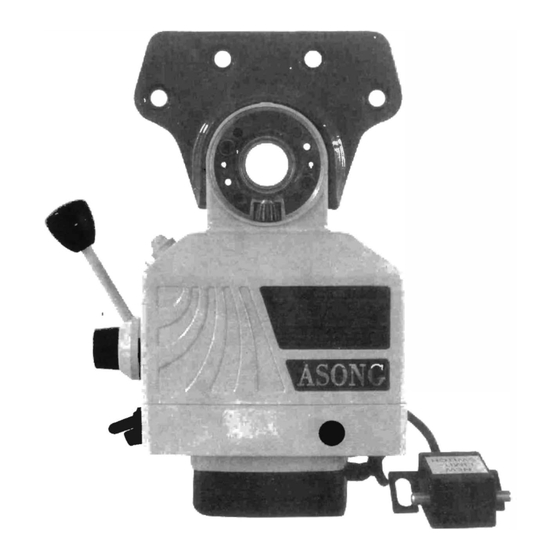
Summary of Contents for Asong POWER FEED
- Page 1 POWER FEED ASSEMBLY & OPERATING INSTRUCTIONS...
-
Page 2: Specification
5, Do not use inappropriate attachments in an attempt to exceed the tool's capacities. 6, Make sure the power feed stops before you change the direction. Welcome to use this power feed. - Page 3 WASHER If the handle is moved to the RAPID SPEED AWITCH right the table will move to the { To let the power feed drive at right. maximum speed > If the handle is moved to the When hold down the yellow...
- Page 4 HOW TO INSTALL T- WAY TRACK FO:l CROSS- FEED T-WAY BAR AND BRACKET FOR LIMIT SWITCH ARE DESIGNED FOR SIMPLE INSTALLATION ON CROSS SLIDE. CROSS TRAVEL LEAD SCREW. CROSS TABLE FIT POWER FEED BODY NEEDLE BEARING BUSHING FIT FLANGE OF TABLE DRILL AND FIT ROLL PIN STAND STAND...
- Page 5 STEP7. NOTE: Install spring handcrank ( already Installed), then AXED SCREW tighten washer and screw. lmportant:For operational safety, please lubricate this part and Install as per instructions. AT FlANGE OF TABLE FIT POWER FEED BODY STANO...
- Page 6 3.lf neces � ary,install an extension shaft appropriate for your T-Table,and assemble the drive gear. 4.Remove the two screws(M8x25)from the small Adapter. 5.Assemble power feed-horizontal to Big Adapter. 6.Adjust she position and clearance of Gears 7. Tighten the screw on the Drive Gear.
- Page 7 ASSY-LIMIT ASSEMBLY INSTRUCTION ·� TRAVEL BLOCK TRAVEL STOP SCREW M8X40 SCREWM8Xl2 LIMIT SWITCH ASSEM BLY�- '- SCREW M8Xl2...
- Page 8 HOW TO OPERATE THE POWER FEED HOW TO INSTALL THE DRIVE UNIT. 1. Move the table to the extreme left-hand position. 2. Slide the bearing face onto the lead-screw. 3. Slide the adaptor onto the bearing face. 4. Secure it to the end of the table with the existing cap-screws.
- Page 9 tf.Fll SCHEMATIC DIAGRAM OF PARTS c�;11 �· · ···· \-a10 BL!l--01 ----..-. � . BWl4J, BL!l--02 \ --; . • 1' 8UHlt CLOII B IJJ.!: 8--0l � ==1- . • BLOi--Ol ---=. � • Cl.Oll � -' __;,t · � ?] / CLOl i BL0!--0<...
-
Page 11: Parts List
PARTS LIST Description CL001 TOP HOUSING CL002 · CLOO� WASHER cl> 35x cl> 45x0.2mm CL004 BEVEL GEAR CLOb5 WASHER cl> 16x cl> 22x0.2mm CL006 LOCKING NUT CLQ07 INNER RING 20/28 CLOOS NEEDLE BEARING CL009 CIRCUIT BREAKER SUPPORT CL009-01 CIRCUIT BREAKER CL009-02 CIRCUIT BREAKER COVER CL009-03... - Page 13 PARTS LIST Description BLOS-15 CRESCENT RING BRUSH HOLDER BL06-01 BRUSH CAP ON-OFF NAME PLATE MICRO SWITCH ASSY. BL08-01 MICRO SWITCH HOLDER Bl08-02 MICRO-SWITCH BL08-03 BL08-04 SCREW DRIVE GEAR ASSY. BL09-01 DRIVE GEAR SHAFT BL09-02 SPRING PIN BL09-03 BEARING BL09-04 DRIVE GEAR BL09-05 SPACER CRESCENT RING...
- Page 14 PARTS LIST Description ZVTEL GEAR ASSY. BL 13-01 ZYTEL GEAR WITHOUT HUB BL 13-02 WASHER BL 13-03 HUB OF ZYTEL GEAR BL 13-04 SPRING WASHER BL 13-05 CRESCENT RING BL14 RANGE SPEED ASSY BL 14-01 BL 14-02 STRAIN OF POTENTIOMETER BL 14-03 SCREW BL 14-04...
- Page 15 PARTS LIST Description Q t y CLOOS WASHER 016x022x0.2mm CL006 LOCKING NUT CL007 INNER RING 20/28 CL009 CIRCUIT BREAKER SUPPORT CL009-01 BREAKER COVER CL027 ADAPTOR Cl043 WASHER SPRING PIN 05x25 SCREW M5x25 WASHER 05 FUSE 05x20 TRAVEL STOP ASSEMBLY STANDARD ACCESSORIES FOR Z AXiS CL002 CL003 WASHER 035x045x0.2mm...
- Page 16 PARTS LIST Description CL028 SPRING ..·.: : PFB-Z-01 EXTENSION SHAFT PFB-Z-02 CLUTCH PFB-Z-03 WASHER PFB-05 T-WAYTRACK PFB-06 LIMIT SWITCH FIXTURE TRAVEL STOP ASSEMBLY CLOOS(Z) WASHER 4> 22x <I> 32x0.2mm KEY 4x25 SPRING PIN <I> 5x30 FUSE <1>5x20 STANDARD ACCESSORIES FOR LONGITUDINAL FEED- HORIZONTAL ARRANGEMENT CL027(W)-1...
-
Page 17: Troubleshooting
DOES NOT GLOW: 1. Ensure there is no problem with power supply. 2. Check if the circuit breker on the power feed unit kicked out. ·3, Check for proper contact at the ON-OFF switch. THE MOTOR DOES NOT WORK WHEN PUSH DIRECTION LEVER TO EITHER LEFT OR RIGHT: 1.
Need help?
Do you have a question about the POWER FEED and is the answer not in the manual?
Questions and answers