Table of Contents
Advertisement
Quick Links
Advertisement
Table of Contents

Related Manuals for RVS systems RoadScope 7


Summary of Contents for RVS systems RoadScope 7
- Page 1 RoadScope Installation Manual Roadscope7 Install Guide...
-
Page 2: Table Of Contents
Table of Contents 1. Precautions 4. Main Body 1.1 General 4.1 Functions & Names 1.2 System Limitation 4.2 Button Operation 1.3 Installation and Safety Precautions 4.3 LED Description 2. System Structure 5. Display device Description 2.1 System Description 5.1 Functions & Names 2.2 Hub Connection Diagram 5.2 Button operation 2.3 Vehicle Wire Pin map... -
Page 3: Precautions
Drivers should concentrate on forward-looking while driving by paying full attention to safe driving. * Roadscope 7 is designed to assist in careful driving , however, it is not a substitute for careful driving practices and the manufacturer of Raodscope 7 takes no responsibility for any damage caused by reckless driving behavior. -
Page 4: System Limitation
Sensitivity setting: * marked parts can be set in R7 manager PC program and ** marked parts can be set in the display device. Roadscope 7 does not output another same-type alarm for 5 seconds after an alarm is generated ( except FCW ) ... -
Page 5: Installation And Safety Precautions
Do not connect or disconnect any cable if vehicle engine is ON. Roadscope 7 does not guarantee 100% accuracy in the detection of front vehicles, driving lanes, pedestrians and traffic signs. The detection rate can be adversely affected by extremely bad weather, road and other abnormal conditions. -
Page 6: System Structure
2. System Structure 2.1 System Description Roadscope7 Main Body System Display Device Hub [ part name: dual hub ] Vehicle connection cable Setup software Program 【 R7 manager program will be provided by the manufacturer separately 】 Please check following parts before installation ①... - Page 7 2. System Structure 2.1 System Description ④ Vehicle Cable : Vehicle power supply and signal input cable ③ Hub : Main body , display device , vibrator 【option】 , vehicle power & signal input ⑤ R7 manager : Setup Software 【 provided separately ⑥...
-
Page 8: Hub Connection Diagram
2. System Structure 2.2 Hub Connection Diagram UART RS232 3G device, Tacho Option etc., Power & Vehicle Signal Option Roadscope7 Install Guide... - Page 9 2. System Structure 2.3 Hub to Vehicle Cable - Pin Map 2.3.1 Basic Connection Wire Name Description Recommend Color IG【ACC】 IG2【Key-On】 power Vehicle Signal BRAKE Brown Brake signal Vehicle Signal TURN_R Yellow Right turn signal a. Vehicle Signal b. CAN Signal TURN_L White Left turn signal...
-
Page 10: R7 Manager
③ Real-time camera image check and image saving ④ Check error code ⑤ Check program version information Manager Connection - Connect Roadscope 7 to R7 manager program by pressing the 'Connect' button【 】. Recommended OS - Window7/8/8.1/10【32/64bit】 Roadscope7 Install Guide... -
Page 11: Installation
3.1 Installation in brief [ please refer to 3.2 for detailed installation methods ] 1.Separate the cover of 4. Connect to R7 Roadscope 7 manager to finish setup 5. Calibrate camera 2. Attach Roadscope 7 angle via R7 manager to the windshield program 3. Connect Roadscope 6. Test drive on the... -
Page 12: Installation In Detail
3. Installation 3.2 Installation in detail Installation & Precautions install the product when parked on the flat ground connect the product when vehicle power is turned off wipe out if dirt is attached to the main body camera ... - Page 13 3. Installation 3.2 Installation in detail 【System Installation】 Install-caution please ensure to place the display device on the dashboard arear where it does not interfere with driver sight ① ② First, connect main body and display device to Hub, ...
- Page 14 3. Installation 3.2 Installation in detail 【Manager Program Connection】 Installation & Precautions The setup process will take around 5 to 10 minutes . Check if the remaining battery power of your laptop is enough before attempting to install . ①...
- Page 15 3. Installation 3.2 Installation in detail 【Angle Adjustment】 If the word 'Calibration' in the middle of the Manager window turns green, firmly fasten the camera . Press the 'Calibration' button of R7 manager. Adjust the angle of the camera by following the red arrow direction.
- Page 16 3. Installation 3.2 Installation in detail 【Install Setting】 Press the 'Setting' button of R7 manager. ① ② ① Camera Height ④ ③ ② ③ Hood Length Car Width ⑤ ⑧ ⑥ Choose the install position ⑦ and input accordingly ④ Camera offset 【Center=0mm】...
- Page 17 3. Installation 3.2 Installation in detail 【General Setting】 ① ③ ② ④ ① set the alarm ON / OFF. ⑤ ② adjust the volume of the alarm. ③ set the Display ON / OFF. ⑥ ④ set the Vibrator ON / OFF. ⑤...
- Page 18 3. Installation 3.2 Installation in detail 【LDW Setting】 ① ② ① set the LDW alarm ON / OFF. ③ ② set LDW function start speed. ③ set the LDW sensitivity of left and right respectively. 【 If input value is smaller, the function will become less responsive 】...
- Page 19 3. Installation 3.2 Installation in detail 【FCW Setting】 ① ① set the FCW alarm ON / OFF. Roadscope7 Install Guide...
- Page 20 3. Installation 3.2 Installation in detail 【HMW Setting】 ① ② ① set the HMW alarm ON / OFF. ③ ② set the HMW function start speed. ③ set the HMW function sensitivity. 【 If input value is smaller, the function will become less responsive 】...
- Page 21 3. Installation 3.2 Installation in detail 【FCDA Setting】 ① ② ① set the FCDA alarm ON / OFF ② set the responsiveness of FCDA notice after the movement of front car - 0 sec: inform immediately if the movement of a front car is detected - 1 sec: inform with 1 second delay if the movement of a front car is detected Roadscope7 Install Guide...
- Page 22 3. Installation 3.2 Installation in detail 【VB Setting】 ① ② ① set the VB alarm ON / OFF. ② set the VB alarm sensitivity. 【 If input value is smaller, the function will become less responsive 】 Roadscope7 Install Guide...
- Page 23 3. Installation 3.2 Installation in detail 【TSR Setting】 ① ① set the TSR alarm ON / OFF Roadscope7 Install Guide...
- Page 24 3. Installation 3.2 Installation in detail 【PD Setting】 ① ② ① set the PD alarm ON / OFF ② set the PD alarm sensitivity. 【 If input value is smaller, the function will become less responsive 】 Roadscope7 Install Guide...
- Page 25 3. Installation 3.2 Installation in detail 【Check Images & Save】 Press the 'Camera Image' button of R7 manager. ① If the 'Camera Image' button is pressed, what camera sees will appear in the middle of R7 manager ② If the 'Image Save' button is pressed, what ①...
- Page 26 3. Installation 3.2 Installation in detail 【Check Information】 ① Press 'Info' button to check following information - Roadscope7 Serial number - Error code - F/W version - R7 Manager version Roadscope7 Install Guide...
- Page 27 Install-caution It is recommended to check system operation while driving in order to confirm the correct installation settings of Roadscope 7. If R7 manager program is connected, you can check whether the speed input is being received correctly and you can also adjust the sensitivity for each function.
-
Page 28: Vehicle Pulse Input
Roadscope 7 can calculate and apply the pulse value during driving even if the vehicle pulse value is unknown. As Roadscope 7 calculates driving speed with the interval of 1 second by detecting the number of pulses, it is not affected by wheel diameter of tire or gear ratio, etc. -
Page 29: Calibration
3. Installation 3.4 Calibration The vanishing point calibration will be implemented to optimize system performance of Roadscope 7 Automatic calibration - When driving speed reaches 70 km/h 【43 mph】 after initial installation, it will automatically calibrate by understanding the driving condition. -
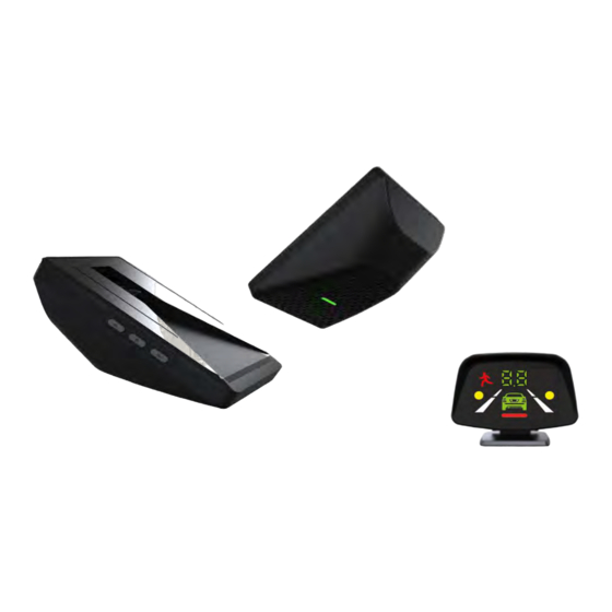
Page 30: Main Body
4. Main Body Description 4.1 Functions & Names Camera Speaker Head Tape LED Lamp Mount Button Cap Cover Roadscope7 Install Guide... - Page 31 4. Main Body Description ① ② 4.2 Button Instruction ③ Function Button Description All functions will be turned OFF if pressed and held for more than 3 ② seconds when the system is ON . Function All functions will be ON if pressed and held for more than 3 seconds ②...
-
Page 32: Led Description
4. Main Body Description 4.3 LED Description Color Status Description flickering Booting up Green At operation-ready status after booting up 【* Green LED will indicate even some of functions are OFF 】 All functions OFF LDW function OFF or inactive Yellow Not possible to output warning signal because of function OFF setting Not possible to operate function because of wiper operation... -
Page 33: Display Device Description
5. Display Device Description 5.1 Functions & Names The display device allows the driver to check detection of lanes, front vehicles , traffic signs , pedestrians and time to collision. Operation Button Adhesive Tape Cable Connector Angle Adjuster【+】 Roadscope7 Install Guide... - Page 34 ① ② ③ 5. Display Device Description 5.2 Button Instruction Function Button Operation ② Press and hold for 3 seconds to turn OFF all functions Function Press and hold for 3 seconds to turn ON all functions ON/OFF 【If a specific function is turned OFF in manager program , the ②...
- Page 35 5. Display Device Description 5.2 Button Instruction Function Button Operation HMW sensitivity setting 【Default setting : 0.7 / setting range , 3rd 0.5~1.2 】, If pressed , it will get less responsive Adjusted TTT Indication Sensitivity If pressed , it will get more responsive Adjusted TTT Indication Manual Before driving the vehicle, press and hold for 3 seconds to enter...
-
Page 36: Graphic Description
5. Display Device Description 5.3 Graphic Interface Description Function Condition UI Operation Description At the end of booting process , All LED lights will be Booting ON for seconds and will be turned off thereafter Power ON TTT indication dot will be ON After Booting 【If all Functions OFF , no indications 】... - Page 37 5. Display device Description 5.3 Graphic Interface Description Function Condition UI Operation Description Warning A red vehicle icon will blink If a pedestrian is detected, a green pedestrian icon Operation will be ON Warning A Red pedestrian icon will blink If driving over the detected speed limit , it will indicate Warning over speed value .
-
Page 38: Diagnosis
6. Diagnosis 6.1 Check Errors Check Errors If there is any Error in Roadscope 7 , the LED will indicate with a constant Yellow light If there is any Error in Roadscope 7, the display device will indicate with constant yellow lights as shown in the left image. - Page 39 7. Repair Handling ① Separate PCB part from bracket ② Separate main body cable ③ Assemble the Bottom cover and CAP cover and return it to receive repair service Roadscope7 Install Guide...
-
Page 40: Specification
8. Specification 1. Normal Operation Voltage 12/24V 2. Min. Operation Voltage 3. Max. Operation Voltage 4. Max. Electric Consumption 2.8W 5. Operating Temperature -30~+85【C】 6. Storage Temperature -40~ +105【C】 7. Camera Type Color CMOS 8. External INTERFACE UART 9. Main Body Size 【mm】 76 x 120 x 46 10.
Need help?
Do you have a question about the RoadScope 7 and is the answer not in the manual?
Questions and answers