Table of Contents
Advertisement
Quick Links
Advertisement
Table of Contents

Related Manuals for Olivetti PG L2140


Summary of Contents for Olivetti PG L2140
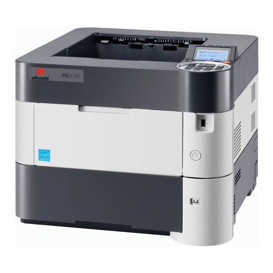
- Page 1 PG L2140 / PG L2145 PG L2150 SERVICE MANUAL...
- Page 2 Notation of products in the manual For the purpose of this service manual, products are identified by print speed at A4. ECOSYS PG L2150 : 50 ppm model ECOSYS PG L2145 : 45 ppm model ECOSYS PG L2140 : 40 ppm model (with Network)
-
Page 3: Revision History
Revision history Revision Date pages Revised contents CONTENTS Correction of Page 11 October 2012 1-3-1 (3) Printing an event log : 1-3-15 to 1-3-16 Installation guide : SSD(HD-6) 1-1-2 Change of Specification Output tray capacity / Faceup : 100 sheets to 250 sheets 1-1-3 Change of Description “Expanded HDD (SSD)”... - Page 4 This page is intentionally left blank.
-
Page 5: Safety Precautions
Safety precautions This booklet provides safety warnings and precautions for our service personnel to ensure the safety of their customers, their machines as well as themselves during maintenance activities. Service personnel are advised to read this booklet carefully to familiarize themselves with the warnings and precautions described here before engaging in maintenance activities. - Page 6 Safety warnings and precautions Various symbols are used to protect our service personnel and customers from physical danger and to prevent damage to their property. These symbols are described below: DANGER: High risk of serious bodily injury or death may result from insufficient attention to or incorrect compliance with warning messages using this symbol.
-
Page 7: Installation Precautions
1. Installation Precautions WARNING • Do not use a power supply with a voltage other than that specified. Avoid multiple connections to one outlet: they may cause fire or electric shock. When using an extension cable, always check that it is adequate for the rated current...................... •... -
Page 8: Precautions For Maintenance
2. Precautions for Maintenance WARNING • Always remove the power plug from the wall outlet before starting machine disassembly....• Always follow the procedures for maintenance described in the service manual and other related brochures............................• Under no circumstances attempt to bypass or disable safety features including safety mechanisms and protective circuits. - Page 9 • Do not remove the ozone filter, if any, from the copier except for routine replacement....... • Do not pull on the AC power cord or connector wires on high-voltage components when removing them; always hold the plug itself......................•...
- Page 10 This page is intentionally left blank.
-
Page 11: Table Of Contents
CONTENTS 1-1 Specifications 1-1-1 Specifications ........................1-1-1 1-1-2 Parts names .......................... 1-1-4 (1) Machine (front side)......................1-1-4 (2) Machine (rear side)......................1-1-6 (3) Operation section ......................1-1-7 1-1-3 Machine cross section ......................1-1-8 (1) 50/45 ppm model......................1-1-8 (2) 40 ppm model........................1-1-9 1-2 Installation 1-2-1 Installation environment...................... -
Page 12: Assembly And Disassembly
1-5 Assembly and disassembly 1-5-1 Precautions for assembly and disassembly................1-5-1 (1) Precautions........................1-5-1 (2) Drum unit .......................... 1-5-1 (3) Toner ..........................1-5-1 1-5-2 Outer covers .......................... 1-5-2 (1) Detaching and refitting the top cover................1-5-2 (2) Detaching and refitting the inlet cover and slot cover............1-5-2 (3) Detaching and refitting the right upper cover.............. - Page 13 2-1 Mechanical Construction 2-1-1 Paper feed/conveying section ....................2-1-1 (1) Cassette paper feed section..................... 2-1-1 (2) MP tray paper feed section....................2-1-2 (3) Conveying section ......................2-1-3 2-1-2 Drum section ......................... 2-1-4 (1) Charger roller unit......................2-1-4 (2) Cleaning unit........................2-1-5 2-1-3 Developer section ........................
- Page 14 This page is intentionally left blank. Service Manual...
-
Page 15: Specifications
1-1 Specifications 1-1-1 Specifications Specifications Item 60 ppm 50 ppm 45 ppm 40 ppm Type Desktop Printing method Electrophotography by semiconductor laser Cassette 60 to 120 g/m Paper weight MP tray 60 to 220 g/m , 230 g/m (Postcard) Plain, Recycled, Bond, Color (Colour), Preprinted, Letterhead, Cassette Prepunched, Rough, High quality, Custom 1 to 8... - Page 16 Specifications Item 60 ppm 50 ppm 45 ppm 40 ppm Resolution Fine1200, Fast1200(KIR), 600dpi(KIR) , 300dpi First print time 9.0 s or less (A4, feed from cassette) Power on/ Warm-up 20 s or less 15 s or less 15 s or less Off mode/ 25 s or less time...
- Page 17 Specifications Item 60 ppm 50 ppm 45 ppm 40 ppm Temperature 10 to 32.5 °C/50 to 90.5 °F Humidity 15 to 80% RH Operating environment Altitude 2,500 m/8,202 ft or less Brightness 1,500 lux or less 380 × 416 × 285 380 ×...
-
Page 18: Parts Names
1-1-2 Parts names (1) Machine (front side) Figure 1-1-1 1. Machine 7. USB memory slot 2. Power switch 8. Top cover 3. Cassette 9. Toner container 4. Paper size label 10. Lock lever (Toner container) 5. Paper width guides 11. - Page 19 Figure 1-1-2 12. Operation panel 17. MP paper feed roller 13. MP (multi purpose) tray 18. Left cover 14. MP middle tray 19. Waste toner box 15. MP top tray 20. Top tray (facedown) 16. MP Paper width guides 21.
-
Page 20: Machine (Rear Side)
(2) Machine (rear side) Figure 1-1-3 22. Rear cover 29. USB port 23. Faceup roller *1 30. Power cord connector 24. Tray attachment plate *2 25. Faceup tray *2 26. Paper stopper *2 *1: 50/45 ppm model only 27. Network interface connector *3 *2: 50/45 ppm model only (Option) 28. -
Page 21: Operation Section
(3) Operation section R R eady eady Data Data Attentio Attention Cancel Logout Menu Back Back Clear Clear Docume ment Box Figure 1-1-4 31. Ready indicator 37. Logout key 43. OK key 32. Data indicator 38. Cancel key 44. Clear key 33. -
Page 22: Machine Cross Section
1-1-3 Machine cross section (1) 50/45 ppm model 10 11 Paper path Paper path (Option) Figure 1-1-5 1. Cassette 10. Drum unit 2. Cassette paper feed section 11. Transfer/Separation section 3. Paper feed conveying section 12. Eject tray (facedown) 4. -
Page 23: Ppm Model
(2) 40 ppm model 10 11 Paper path Paper path (Option) Figure 1-1-6 1. Cassette 10. Drum unit 2. Cassette paper feed section 11. Transfer/Separation section 3. Paper feed conveying section 12. Eject tray (facedown) 4. MP tray 13. Eject section 5. - Page 24 This page is intentionally left blank. 1-1-10 Y 114940 - 1 Service Manual...
-
Page 25: Installation Environment
1-2 Installation 1-2-1 Installation environment 1. Temperature: 10 to 32.5°C/50 to 90.5°F 2. Humidity: 15 to 80% RH 3. Power supply: 120 V AC, 12.0 A 220 - 240 V AC, 6.5 A 4. Power supply frequency: 50 Hz ±2%/60 Hz ±2% 5. -
Page 26: Unpacking And Installation
1-2-2 Unpacking and installation Unpacking Figure 1-2-2 1. Outer case 8. Upper pad L 2. Inner case 9. Operation guide 3. Bottom pad R 10. Operation sheets Assy *1 4. Bottom pad L 11. Waste toner bottle 12. Power cord 5. - Page 27 Removing the tapes and pads 1. Remove two tapes. 2. Remove the protection sheet. Tape Protection sheet Tape Figure 1-2-3 3. Remove four tapes. Tape Tape Tape Tape Figure 1-2-4 1-2-3 Service Manual Y 114940 - 1 Y 114940 - 1...
- Page 28 (50/45 ppm model only) Top cover 4. Open the top cover. 5. Remove the tape and the spacer. Spacer Tape Figure 1-2-5 Installing the toner container 1. Open the top cover. 2. Remove the container label by pulling forwards. Top cover Caution: Check the contents of the container label and remove a container.
- Page 29 3. Rotate the toner container lock lever to Lock position the lock position and then remove the Unlock position toner container from the printer by returning it to the unlock position. Shipment position Toner container Toner container lock lever Printer Figure 1-2-7 4.
- Page 30 Installing the waste toner box 1. Openthe left cover. 2. Open the cap of the waste toner box. 3. Install the waste toner box. 4. Close the left cover. Waste toner box Left cover Figure 1-2-9 Setting of the fuser pressure release lever (40 ppm model only) 1.
- Page 31 Loading paper (40 ppm model only) 1. Pull the cassette from the printer out. (40 ppm model only) 2. Push the bottom plate down. Cassette Botom plate Figure 1-2-11 (Common) Cassette size window 3. Turn the cassette size dial so that the size of the paper you are going to use appears in the cassette size window.
- Page 32 5. Push the lock lever and slide the paper Paper length guide length guide to the desired paper size. If you are going to set paper that is lon- ger than A4, pull out the extension cas- settes pushing the lock button one by one and adjust them to the desired paper size.
- Page 33 Replace the operation panel sheet (except 240V AC model) 1. Rotate the operation panel ring in the counterclockwise direction. 2. Remove the operation panel cover. 3. Replace it to the operation panel sheet of the corresponding language. 4. Refit all the removed parts. Operation panel ring Operation panel...
- Page 34 Connecting the cable 1. Open the rear cover. 2. Remove the inlet cover. 3. Connect the USB interface cable to the printer and PC. USB interface cable Inlet cover Figure 1-2-18 4. Connect the network interface cable to the printerand network. Network interface cable Figure 1-2-19...
- Page 35 Power on Ready indicator 8. Press the power switch and then check the lighting up of ready indicator. 9. Installing the printer driver (refer to operation guide). Power switch Figure 1-2-21 Setting the language 1. Press the menu key. 2.
-
Page 36: Install The Expansion Memory (Option)
1-2-3 Install the expansion memory (option) Procedure 1. Remove the inlet cover. 2. Remove the slot cover. 3. Unplug the power cable. Caution: Do not insert or remove main PWB assembly while machine power is Slot cover Doing so may cause damage to the machine and the main PWB. -
Page 37: Install The Memory Card (Sd Card) (Option)
1-2-4 Install the memory card (SD card) (option) Procedure 1. Remove the main PWB assembly from the machine. (SeePage 1-2-12) 2. SD card is inserted in a SD card slot. Maximum memory capacity 32 GB. 3. Remove the main PWB assmbly and the covers. -
Page 38: Option Composition
2LV/2L1/2L2/2MS/2MT 1-2-5 Option composition Expansion Memory SD Memory Card Faceup Output Tray PT-320 (DIMM 256 MB/ SDHC Memory Card (60/50/45 ppm model only) 512 MB/1 GB) USB Flash Memory Gigabit Ethernet Board SSD HD-6 IB-50 Attchment PB-325 Wireless LAN Parallel interface card Interface Card... -
Page 39: Service Mode
1-3 Maintenance Mode 1-3-1 Service mode The machine is equipped with a maintenance function which can be used to maintain and service the machine. (1) Executing a service mode Start Press the Menu key. The Mode Selection Menu appears. Select [Adjust/Maint.] using the cursor The Adjust/Maintenance menu appears. -
Page 40: Description Of Service Mode
(2) Description of service mode Service items Description Service Status Printing a status page for service purpose Description Prints a status page for service purpose. The status page includes various settings and service cumulative. Purpose To acquire the current printing environmental parameters and cumulative information. Method 1. -
Page 41: Service Status Page
Service items Description Service status page (1) Service Status Page Printer 2012/04/19 16:39 Firmware version 2LV_2000.000.000 2012.04.19 [XXXXXXXX] [XXXXXXXX] [XXXXXXXX] Controller Information Memory status Standard Size 128.0 KB Option Slot 128.0 KB Total Size 256.0 KB Time +01:00 Tokio Local Time Zone (10) Date and Time... - Page 42 Service items Description Service status page (2) Service Status Page Printer 2012/04/19 16:39 Firmware version 2LV_2000.000.000 2012.04.19 [XXXXXXXX] [XXXXXXXX] [XXXXXXXX] Engine Information Send Information NVRAM Version _1F31225_1F31225 10/06/19 16:39 (30) (32) Date and Time MAC Address 00:C0:EE:D0:01:0D Address (31) (33) (34) (35) 100/100...
- Page 43 Service items Description Detail of service status page Description Supplement Firmware version System date Engine soft version Engine boot version Operation panel mask version Machine serial number Standard memory size Optional memory size Total memory size (10) Local time zone (11) Report output date Day/Month/Year hour:minute (12) NTP server name...
- Page 44 Service items Description Detail of service status page Description Supplement (25) Page of relation to the A4/Letter - (26) Average coverage for printer Black (27) Coverage on the final output page (28) FRPO setting (29) RP Code Code the engine software version and the date of update.
- Page 45 Service items Description Description Supplement (40) Life counter (The first line) Machine life/MP tray/Cassette/Paper feeder 1/ Paper feeder 2/Paper feeder 3/Paper feeder 4/Duplex Life counter (The second line) Bulk Feeder counter/Drum counter K/ Developer counter K/Maintenance kit counter (41) Panel lock information F00: OFF F01: Partial Lock 1 F02: Partial Lock 2...
- Page 46 Service items Description Description Supplement (58) RFID information Product (OEM/maker) / destination code / a toner name / lot number / toner capacity / toner empty infor- mation / number of times of toner refilling (59) Toner install mode information 0:OFF t:ON (60)
- Page 47 Service items Description Description Supplement (78) The last page printing rate of 0.00 to 100.00(%) each area (79) The average printing rate of 0.00 to 100.00(%) each area (80) The average printing rate for the 0.00 to 100.00(%) 1000 past (81) The average printing rate for the 0.00 to 100.00(%)
- Page 48 Service items Description Network Status Printing a status page for network Description Prints a status page for network. Execution is possible only the model with network. Purpose To acquire the detailed network setting information. Method 1. Enter the Service Setting menu. 2.
- Page 49 Service items Description Test Page Printing a test page Description The test page is printed with halftones. Purpose To check the activation of the developer and drum units. Method 1. Enter the Service Setting menu. 2. Select [Test Page] using the cursor up/down keys. 3.
- Page 50 Service items Description Maintenance Counter reset for the maintenance kit Description The "Install MK" message means that maintenance kit should be replaced at fixed pages of printing. The interval counter must be manually reset using this service item. Maintenance kit MK-3102 (for 120 V ) (40 ppm) :300,000 images Maintenance kit MK-3132 (for 120 V ) (50/45 ppm) :500,000 images...
- Page 51 Service items Description Initializing the developing unit (toner install mode) New Developer Description The new developing unit is shipped from the factory with no toner contained. The devel- oping unit can be automatically replete with toner when a toner container is installed onto it and the printer is turned on.
- Page 52 Service items Description Drum Drum surface refreshing Description Rotates the drum approximately 3 minutes with toner lightly on the overall drum using the high-voltage output control. The cleaning blade in the drum unit scrapes toner off the drum surface to clean it. Purpose To clean the drum surface when image failure occurs due to the drum.
- Page 53 Service items Description Altitude adj. Setting altitude adjustment Description Sets the altitude adjustment mode. Purpose Used when print quality deteriorates in an installation at the altitude of 1,500 meters or higher. Method 1. Enter the Service Setting menu. 2. Select [Altitude Adj.] using the cursor up/down keys. 3.
-
Page 54: Printing An Event Log
(3) Printing an event log Service items Description Printing an Printing an event log (EVENT LOG) event log Description Prints a history list of occurrences of paper jam, self-diagnostics, toner replacements, etc. Purpose To allow machine malfunction analysis based on the frequency of paper misfeeds, self diagnostic errors and replacements. - Page 55 Service items Description Printing an Remarks: Details of configurations (See above 5.) event log Notes on Connecting to USB (1)Save the PRESCRIBE commands above as a text file in the PC. (2)Select the Sharing tab of the printer properties and share the printer. (3)Select a USB port in the Port tab.
-
Page 56: Event Log
Service items Description Event log Event Log Printer 19/June/2010 08:40 Firmware version 2LV_2000.000.000 2010.06.19 [XXXXXXXX] [XXXXXXXX] [XXXXXXXX] Paper Jam Log (11) Counter Log Count. Event Descriprions 1876543 0501.01.08.01.01 J0100: J4201: C0030: T00: 166554 4020.01.08.01.01 J0105: J4202: C0070: T01: 4988 0501.01.08.01.01 J0106: J4203:... - Page 57 Service items Description Items Description Paper Jam Count. Event Remembers 1 to 16 of The total page count at Log code (hexadeci- occurrence. If the the time of the paper mal, 5 categories) occurrence of the previ- jam. ous paper jam is less (a) Cause of a paper than 16, all of the paper jams are logged.
- Page 58 Service items Description Items Description Paper Jam 1604: PF feed sensor 2 non arrival jam (cassette 4) cont 1605: PF feed sensor 2 non arrival jam (cassette 5) 1614: PF feed sensor 2 stay jam (cassette 4) 1615: PF feed sensor 2 stay jam (cassette 5) 1805: PF feed sensor 3 non arrival jam (cassette 5) 1815: PF feed sensor 3 stay jam (cassette 5) 4002: Registration sensor 2 non arrival jam (cassette 2)
- Page 59 Service items Description Items Description Paper Jam 4401: Duplex sensor 2 non arrival jam (cassette 1) cont 4402: Duplex sensor 2 non arrival jam (cassette 2) 4403: Duplex sensor 2 non arrival jam (cassette 3) 4404: Duplex sensor 2 non arrival jam (cassette 4) 4405: Duplex sensor 2 non arrival jam (cassette 5) 4409: Duplex sensor 2 non arrival jam (MP tray or bulk feeder) 4418: Duplex sensor 2 stay jam (duplex section)
- Page 60 Service items Description Items Description Service Call Count. Service Code Remembers 1 to 8 The total page Self diagnostic error code of occurrence of self count at the time (See page 1-4-8) diagnostics error. If of the self diag- the occurrence of nostics error.
- Page 61 Service items Description Items Description (11) Counter Log (f) Paper jam (g) Self diagnostic (h) Maintenance item replac- error Comprised of Indicates the Indicates the log Indicates the log counter three log log counter of counter of self diag- depending on the mainte- counters paper jams...
- Page 62 This page is intentionally left blank. 1-3-24 Y 114940 - 1 Service Manual...
-
Page 63: Paper Misfeed Detection
1-4 Troubleshooting 1-4-1 Paper misfeed detection (1) Paper misfeed indication When a paper misfeed occurs, the machine immediately stops printing and displays the paper misfeed mes- sage on the operation panel. To remove paper misfeed in the machine, pull out the cassette, open the front cover or the rear cover. -
Page 64: Bulk Paper Feeder)
(2-2) PF-315+ (Bulk Paper Feeder) MPPS PFLS5 PS1/PS2 RS1(3) PFPFS5 DUS1 DUS2 Figure 1-4-2 Paper jam location (A)Misfeed in cassette1 (B)Misfeed in paper feed section (C)Misfeed in MP tray (D)Misfeed in bulk paper feeder (Option) (E)Misfeed in cassette2 (Option) (F)Misfeed in cassette3 (Option) (G)Misfeed in cassette4 (Option) (H)Misfeed in cassette5 (Option) - Page 65 Code Contents Conditions location* 0000 Initial jam The power is turned on when a sensor in the con- veying system is on. 0100 Secondary paper feed Secondary paper feed request given by the con- request time out troller is unreachable. 0101 Waiting for process package Process package won’t be ready.
- Page 66 Code Contents Conditions location* 0511 Multiple sheets of jam The registration sensor 2 (RS2) does not turn off during paper feed from cassette 1. 0512 PF feed sensor 1 (PFPFS1) does not turn off dur- ing paper feed from cassette 2. 0513 PF feed sensor 2 (PFPFS2) does not turn off dur- ing paper feed from cassette 3.
- Page 67 Code Contents Conditions location* 4002 Registration sensor 2 non The registration sensor 2 (RS2) does not turn on arrival jam during paper feed from cassette 2. 4003 The registration sensor 2 (RS2) does not turn on during paper feed from cassette 3. 4004 The registration sensor 2 (RS2) does not turn on during paper feed from cassette 4.
- Page 68 Code Contents Conditions location* 4111 Registration sensor 3 stay The registration sensor 3 (RS3) does not turn off during paper feed from cassette 1. 4112 The registration sensor 3 (RS3) does not turn off during paper feed from cassette 2. 4113 The registration sensor 3 (RS3) does not turn off during paper feed from cassette 3.
- Page 69 Code Contents Conditions location* 4211 Ejetct sensor stay jam The eject sensor (ES) does not turn off during I or L paper feed from cassette 1. 4212 The eject sensor (ES) does not turn off during I or L paper feed from cassette 2.
-
Page 70: Self-Diagnostic Function
1-4-2 Self-diagnostic function (1) Self-diagnostic function This machine is equipped with self-diagnostic function. When a problem is detected, the machine stops print- ing and display an error message on the operation panel. An error message consists of a message prompting a contact to service personnel and a four-digit error code indicating the type of the error. - Page 71 Check procedures/ Code Contents Causes corrective measures 0170 Billing counting error Data damage of Contact the Service Administrative Division. EEPROM. A checksum error is detected Defective PWB. Replace the main PWB or the engine PWB in the main and engine and check for correct operation (see page 1- backup memories for the bill- 5-22, 1-5-22).
- Page 72 Check procedures/ Code Contents Causes corrective measures 1020 PF lift motor 1 error Defective bottom Check to see if the bottom plate can move (paper feeder) plate elevation smoothly and repair it if any problem is mechanism in the found.
- Page 73 Check procedures/ Code Contents Causes corrective measures 1040 PF lift motor 3 error Defective bottom Check to see if the bottom plate can move (paper feeder) plate elevation smoothly and repair it if any problem is mechanism in the found.
- Page 74 Check procedures/ Code Contents Causes corrective measures 1150 BPF lift motor downward Defective connec- Reinsert the connector. Also check for conti- error (Bulk paper feeder) tor cable or poor nuity within the connector cable. If none, contact in the con- replace the cable.
- Page 75 Check procedures/ Code Contents Causes corrective measures 1830 Paper feeder 4 communica- Improper installa- Follow installation instruction carefully again. tion error tion paper feeder. Defective connec- Reinsert the connector. Also check for conti- A communication error is tor cable or poor nuity within the connector cable.
- Page 76 Check procedures/ Code Contents Causes corrective measures 2010 Main motor steady-state Defective connec- Reinsert the connector. Also check for conti- error tor cable or poor nuity within the connector cable. If none, contact in the con- replace the cable. Stable OFF is detected for 2 s nector.
- Page 77 Check procedures/ Code Contents Causes corrective measures 2330 Fuser pressure release Defective connec- Reinsert the connector. Also check for conti- motor error tor cable or poor nuity within the connector cable. If none, (Over-current) contact in the con- replace the cable. (50/45 ppm model only) nector.
- Page 78 Check procedures/ Code Contents Causes corrective measures 2610 PF drive motor 2 error Defective connec- Reinsert the connector. Also check for conti- (paper feeder 2) tor cable or poor nuity within the connector cable. If none, contact in the con- replace the cable.
- Page 79 Check procedures/ Code Contents Causes corrective measures 4200 BD steady-state error Defective connec- Reinsert the connector. Also check for conti- tor cable or poor nuity within the connector cable. If none, When the value of Register contact in the con- replace the cable.
- Page 80 Check procedures/ Code Contents Causes corrective measures 6020 Abnormally high fuser Deformed connec- See page 1-4-19. thermistor 2 temperature tor pin. (50/45 ppm model only) Defective triac. See page 1-4-19. Shorted fuser Replace the fuser unit (see page 1-5-19). The detection temperature of thermistor.
- Page 81 Check procedures/ Code Contents Causes corrective measures 6000/ Broken fuser heater wire Deformed connec- If the I/F connector pins of the fuser unit and 6020/ Abnormally high fuser tor pin. the main unit are deformed owing to foreign thermistor 2 temperature matters, replace the connectors or the units 6030/ Broken fuser thermistor 2...
- Page 82 Check procedures/ Code Contents Causes corrective measures 6120 Abnormally high fuser Deformed connec- See page 1-4-19. thermistor 1 temperature tor pin. Defective triac. See page 1-4-19. (50/45 ppm model) Shorted fuser Replace the fuser unit (see page 1-5-19). The detection temperature of thermistor.
- Page 83 Check procedures/ Code Contents Causes corrective measures 6400 Zero-cross signal error Defective connec- Reinsert the connector. Also check for conti- tor cable or poor nuity within the connector cable. If none, While fuser heater control is contact in the con- replace the cable.
- Page 84 Check procedures/ Code Contents Causes corrective measures 7410 Drum unit type mismatch Defective connec- Reinsert the connector. Also check for conti- error tor cable or poor nuity within the connector cable. If none, contact in the con- replace the cable. The drum PWB EEPROM nector.
- Page 85 Check procedures/ Code Contents Causes corrective measures F000 Main PWB - operation PWB Defective connec- Reinsert the connector. Also check for conti- communication error tor cable or poor nuity within the connector cable. If none, contact in the con- replace the cable.
-
Page 86: Image Formation Problems
1-4-3 Image formation problems If the part causing the problem was not supplied, use the unit including the part for replacement. (1) No image (2) No image (3) Image is too (4) The back- (5) White streaks appears (entirely appears (entirely light. -
Page 87: No Image Appears (Entirely White)
(1) No image appears (entirely white). Print example Causes Check procedures/corrective measures Defective Defective connector cable Reinsert the connector. Also check for conti- developer or poor contact in the con- nuity within the connector cable. If none, bias output. nector. -
Page 88: Image Is Too Light
(3) Image is too light. Print example Causes Check procedures/corrective measures Dew condensation of the drum surface. Perform the drum surface refreshing in a sys- tem menu. The paper is moist. The storage state of a paper is checked. Defective Defective connector cable Reinsert the connector. -
Page 89: The Background Is Colored
(4) The background is colored. Print example Causes Check procedures/corrective measures Defective Defective connector cable Reinsert the connector. Also check for conti- main or poor contact in the con- nuity within the connector cable. If none, charger out- nector. replace the cable. -
Page 90: Black Streaks Are Printed Vertically
(6) Black streaks are printed vertically. Print example Causes Check procedures/corrective measures Dirty or flawed drum. Perform the drum surface refreshing operation. Flawed drum. Replace the drum unit (see page 1-5-15). Deformed or worn cleaning Replace the drum unit (see page 1-5-15). blade in the drum unit. -
Page 91: Image Is Blurred
(9) Image is blurred. Print example Causes Check procedures/corrective measures Deformed press roller. Replace the fuser unit (see page 1-5-19). Paper conveying section drive Check the gears and belts and, if necessary, grease them. problem. (10) Paper is wrinkled. Print example Causes Check procedures/corrective measures... -
Page 92: Fusing Is Loose
(13) Fusing is loose. Print example Causes Check procedures/corrective measures Wrong types of paper. Check if the paper meets specifications, replace paper. Setup of media Practical use of half speed printing Paper creased. Replace the paper. Flawed heat roller or press Replace the fuser unit (see page 1-5-19). -
Page 93: Electric Problems
1-4-4 Electric problems If the part causing the problem was not supplied, use the unit including the part for replacement. Troubleshooting to each failure must be in the order of the numbered symptoms. Problem Causes Check procedures/corrective measures 1. No electricity at the Measure the input voltage. - Page 94 Problem Causes Check procedures/corrective measures 1. Defective connector Reinsert the connector. Also check for continuity within the Developer fan cable or poor con- connector cable. If none, replace the cable. motor does not tact in the connector. Developer fan motor and fuser thermistor connect PWB operate.
- Page 95 Problem Causes Check procedures/corrective measures (12) 1. Defective connector Reinsert the connector. Also check for continuity within the Feedshift solenoid cable or poor con- connector cable. If none, replace the cable. does not operate. tact in the connector. Feedshift solenoid and relay-L PWB (YC13) (50/45 ppm Relay-L PWB and engine PWB (YC2/YC3) model only)
- Page 96 Problem Causes Check procedures/corrective measures (16) 1. Defective connector Reinsert the connector. Also check for continuity within the A paper jam in the cable or poor con- connector cable. If none, replace the cable. paper feed, paper tact in the connector. Regist sensor 2 and Drum PWB (YC6) conveying or eject DU sensor 1 and Relay-L PWB (YC9)
-
Page 97: Mechanical Problems
1-4-5 Mechanical problems If the part causing the problem was not supplied, use the unit including the part for replacement. Problem Causes/check procedures Corrective measures Check if the surfaces of the following roll- Clean with isopropyl alcohol. No primary paper ers are dirty with paper powder. - Page 98 This page is intentionally left blank. 1-4-36 Y 114940 - 1 Service Manual...
-
Page 99: Precautions For Assembly And Disassembly
1-5 Assembly and disassembly 1-5-1 Precautions for assembly and disassembly (1) Precautions Before starting disassembly, push the power switch and check the disappeared display of an operation panel certainly. Unplug the power cable from the wall outlet. When handling PWBs (printed wiring boards), do not touch parts with bare hands. The PWBs are susceptible to static charge. -
Page 100: Outer Covers
1-5-2 Outer covers (1) Detaching and refitting the top cover Procedure Top cover 1. Open the rear cover. Screw Screw 2. Open the top cover. 3. Remove two screws. Hook Hook 4. Release two hooks and then lift the top cover upward. -
Page 101: Detaching And Refitting The Right Upper Cover
(3) Detaching and refitting the right upper cover Procedure Screw 1. Open the front cover. Right upper 2. Remove the top cover assembly. cover (See page 1-5-3) 3. Remove the slot cover. (See page 1-5-3) 4. Remove two screws. 5. -
Page 102: Detaching And Refitting The Rear Left Cover
(5) Detaching and refitting the rear left cover Procedure 1. Open the rear cover. 2. Release two hooks of the rear left cover Rear left cover while pulling forward. 3. Remove the rear left cover by rotating. Hook Hook Figure 1-5-7 (6) Detaching and refitting the left upper cover Procedure... -
Page 103: Detaching And Refitting The Left Lower Cover
(7) Detaching and refitting the left lower cover Procedure 1. Remove the left upper cover. (See page 1-5-5) 2. Pull out the cassette. 3. Remove the rear left lower cover. (See page 1-5-5) Hook B 4. Remove the screw. 5. - Page 104 Fulcrum axis 5. Remove the fulcrum axis by sliding the (Rear cover assembly) rear cover assembly while avoiding rear cover and then remove the rear cover assembly. Rear cover assembly Rear cover Figure 1-5-11 1-5-6 Y 114940 - 1 Service Manual...
-
Page 105: Paper Feed Section
1-5-3 Paper feed section (1) Detaching and refitting the paper feed roller Procedure Paper feed roller assembly 1. Pull out the cassette. 2. Release the lock by pulling the lever. Holder 3. Remove the paper feed roller assembly by pulling and raising and then sliding forward. -
Page 106: Detaching And Refitting The Mp Paper Feed Pulley
Retard roller guide 2. Remove the spring. 3. Remove the retard roller holder by Retard roller holder rotating. 4. Check or replace the retard roller and refit all the removed parts. Spring Figure 1-5-14 (3) Detaching and refitting the MP paper feed pulley Procedure 1. - Page 107 4. Remove the fulcrum of leftside by extending a cover. 5. Remove the fulcrum of rightside during twisting a cover. 6. Remove the front cover forward. Front cover Front cover Figure 1-5-16 1-5-9 Service Manual Y 114940 - 1 Y 114940 - 1...
- Page 108 7. Remove two screws on the MP paper feed unit. Screw MP paper feed unit Screw Figure 1-5-17 8. Remove the MP paper feed unit from the printer. Printer MP paper feed unit Figure 1-5-18 1-5-10 Y 114940 - 1 Service Manual...
- Page 109 MP paper feed 9. Release the lock lever and then slide pulley axis the MP paper feed pulley axis. 10. Remove MP paper feed pulley. 11. Check or replace the MP paper feed pulley and refit all the removed parts. Lock lever MP paper feed pulley Figure 1-5-19...
-
Page 110: Developer Section
1-5-4 Developer section (1) Detaching and refitting the developer unit Procedure Top cover 1. Open the top cover. 2. Release the lock lever by rotating and then remove the toner container. Toner container Lock lever Figure 1-5-20 3. Open the front cover. 4. - Page 111 Developer unit 6. Pull the connector out. 7. Release the lock lever and then remove the developer unit upward. Connector 8. Check or replace the developer unit and refit all the removed parts. Connector Lock lever Figure 1-5-22 1-5-13 Service Manual Y 114940 - 1 Y 114940 - 1...
-
Page 112: Drum Section
1-5-5 Drum section (1) Detaching and refitting the drum unit Procedure 1. Remove the developer unit. (See page 1-5-13) Drum unit 2. Remove the lock lever L. 3. Remove the lock lever R by sliding backward. 4. Remove the drum unit by sliding forward. -
Page 113: Transfer/Separation Section
1-5-6 Transfer/separation section (1) Detaching and refitting the transfer roller assembly Procedure 1. Release four hooks by sliding to left the paper chute guide. 2. Remove the paper chute guide upward. Paper chute guide Hooks Figure 1-5-25 Transfer roller Transfer roller 3. -
Page 114: Detaching And Refitting The Separation Needle Unit
(2) Detaching and refitting the separation needle unit Procedure 1. Remove the transfer roller unit. (See page 1-5-16) Separation 2. Release four hooks of separation nee- needle unit dle unit by rotating and then remove the Hooks separation needle unit upward. 3. -
Page 115: Optical Section
1-5-7 Optical section (1) Detaching and refitting the laser scanner unit Procedure Screw Screw 1. Remove the top cover assembly. Screw (See page 1-5-3) Screw 2. Remove the right upper cover. (See page 1-5-4) 3. Pull the connector and FFC from engine PWB out. -
Page 116: Fuser Section
1-5-8 Fuser section (1) Detaching and refitting the fuser unit Procedure 1. Remove the rear cover. (See page 1-5-6) 2. Remove the screw and then remove the connector cover A. 3. Pull two connectors out. Connectors connector Screw cover A Figure 1-5-29 4. - Page 117 [50/45 ppm model] 8. Remove the screw and then remove the fuser unit forward. 9. Check or replace the fuser unit and refit all the removed parts. Caution: when refitting the fuser unit, per- form the following procedures. (1)Turn on the power switch while opening the rear cover after removing the fuser unit.
-
Page 118: Ejection Section
1-5-9 ejection section (1) Detaching and refitting the ejection unit Procedure 1. Remove the top cover assembly. Ejection unit (See page 1-5-3) Screw 2. Remove the right upper cover and the Screw right lower cover. (See page 1-5-4) 3. Remove the left upper cover. (See page 1-5-5) 4. -
Page 119: Pwbs
1-5-10 PWBs (1) Detaching and refitting the main PWB Procedure 1. Remove the inlet cover and the slot cover.(See page 1-5-3) 2. Unplug the power cable. Caution: Do not insert or remove main PWB assembly while machine power is Doing so may cause damage to the machine and the main PWB. - Page 120 7. Pull two connectors out. 8. Remove the screw and two hooks and Hook then remove the wire guide. Connector Wire guide Hook Connector Screw Figure 1-5-36 9. Pull all connectors out from main PWB. 10. Remove four screws and then remove the engine PWB.
-
Page 121: Detaching And Refitting The Relay-L Pwb
(3) Detaching and refitting the relay-L PWB Procedure 1. Remove the top cover assembly. (See page 1-5-3) 2. Pull the connectors out from relay-L LSU fan motor assembly PWB and then release the wires from hooks. 3. Remove the LSU fan motor assembly upward. -
Page 122: Detaching And Refitting The Power Source Pwb
(4) Detaching and refitting the power source PWB Procedure 1. Remove the top cover assembly. (See page 1-5-3) 2. Remove the right upper cover. (See page 1-5-4) 3. Remove the right lower cover. Screw (See page 1-5-4) 4. Remove the main PWB. (See page 1-5-22) 5. -
Page 123: Detaching And Refitting The High Voltage Pwb
(5) Detaching and refitting the high voltage PWB Procedure 1. Remove the cassette. Screw 2. Remove the right upper cover and the right lower cover. (See page 1-5-4) 3. Remove the left upper cover and the left lower cover. (See page 1-5-6) 4. - Page 124 9. Remove seven screws. 10. Extract the feed roller axis by pushing the joint part. 11. Remove the DU assy to the front. Screw Screw Joint part Screw Screws DU assy Paper feed roller axis Screws Figure 1-5-44 12. Remove the screw. 13.
-
Page 125: Detaching And Refitting The Operation Pwb
(6) Detaching and refitting the operation PWB Procedure 1. Open the top cover. Screws 2. Remove the JAM processing procedure sheet. 3. Remove three screws. Screw JAM processing procedure sheet Top cover Figure 1-5-46 4. Rotate the operation PWB cover. 5. -
Page 126: Others
1-5-11 Others (1) Detaching and refitting the main driving motor unit Procedure 1. Remove the right upper cover. Connector (50/45 ppm) Wire (See page 1-5-4) holder 2. Remove the right lower cover. (See page 1-5-4) 3. Pull the connector out from the motor and then release the wires from wire holder. -
Page 127: Detaching And Refitting The Paper Feed Driving Motor Unit
(2) Detaching and refitting the paper feed driving motor unit Procedure Connector 1. Remove the right upper cover. (See page 1-5-4) 2. Remove the right lower cover. (See page 1-5-4) 3. Pull the connectors of clutches and solenoid out. 4. -
Page 128: Direction Of Installing The Principal Fan Motors
(4) Direction of installing the principal fan motors When detaching or refitting the fan motor, be careful of the airflow direction (intake or exhaust). Power source fan motor (Rating label: inside) Intake Developer fan motor (Rating label: inside) Intake Intake LSU fan motor (Rating label: inside) - Page 129 This page is intentionally left blank. 1-5-31 Service Manual Y 114940 - 1 Y 114940 - 1...
-
Page 130: Upgrading The Firmware
1-6 Requirements on PWB Replacement 1-6-1 Upgrading the firmware Follow the procedure to upgrade the firmware below. * Main PWB (CTRL) * PF main PWB (PF) * Engine PWB (ENGN) * Language data (OPT) Preparation Extract the file that has the download firmware and put them in the USB Memory. NOTE: To improve Firmware Upgrade speed, a separate SKIP file can be added to the USB Memory Stick with the Firmware Upgrade package. -
Page 131: Remarks On Pwb Replacement
1-6-2 Remarks on PWB replacement (1) Engine PWB NOTE: When replacing the PWB, remove the Engine PWB EEPROM from the PWB and then reattach it to the new PWB. EEPROM(U21) Figure 1-6-2 1-6-2 Service Manual Y 114940 - 1 Y 114940 - 1... -
Page 132: Paper Feed/Conveying Section
2-1 Mechanical Construction 2-1-1 Paper feed/conveying section Paper feed/conveying section consists of the paper feed unit that feeds paper from the cassette and the MP tray paper feed unit that feeds paper from the MP tray, and the paper conveying section that conveys the fed paper to the transfer/separation section. -
Page 133: Mp Tray Paper Feed Section
(2) MP tray paper feed section The MP tray can contain 100 sheets. Feeding from the MP tray is performed by the rotation of the MP paper feed roller. Also, function of the MP separation pad prevents paper from multiple feeding. Figure 2-1-3 MP tray paper feed section 1. -
Page 134: Conveying Section
(3) Conveying section The conveying section conveys paper to the transfer/separation section as paper feeding from the cassette or MP tray, or as paper refeeding for duplex printing. Paper by feeding is conveyed by the paper feed roller to the position where the registration sensor (RS) is turned on, and then sent to the transfer/separation section by the upper registration roller and lower registration roller. -
Page 135: Drum Section
2-1-2 Drum section The drum section consists of the drum, the charger roller unit, and the cleaning unit, and the drum surface is uniformly charged in preparation for formation of residual image by laser beam. (1) Charger roller unit The drum surface is uniformly charged by contacting the roller which gave the electric charge and was charged on the drum surface, and rotating it. -
Page 136: Cleaning Unit
(2) Cleaning unit After transfer is complete, toner remaining on the drum surface is chipped off with the cleaning blade and is collected to the waste toner box with the drum screw. The cleaning lamp (CL) consists of LEDs and removes residual charge on the drum before main charging. -
Page 137: Developer Section
2-1-3 Developer section The developer unit consists of the developer roller that forms the magnetic brush, the developer blade and the developer screws that agitate the toner.Also, the toner sensor (TS) checks whether or not toner remains in the developer unit. Figure 2-1-11 Developer section 1. -
Page 138: Optical Section
2-1-4 Optical section (1) Laser scanner section The charged surface of the drum is then scanned by the laser beam from the laser scanner unit. The laser beam is dispersed as the polygon motor (PM) revolves to reflect the laser beam over the drum. Various lenses and mirror are housed in the laser scanner unit, adjust the diameter of the laser beam, and focalize it at the drum surface. -
Page 139: Transfer/Separation Section
2-1-5 Transfer/Separation section The transfer and separation section consists mainly of the transfer roller and separation electrode. A high voltage generated by the high voltage PWB (HVPWB) is applied to the transfer roller for transfer charg- ing. Paper after transfer is separated from the drum by applying separation charging that is output from the high voltage PWB (HVPWB) to the separation electrode. -
Page 140: Fuser Section
2-1-6 Fuser section The paper sent from the transfer/separation section is interleaved between the heat roller and the press roller. The heat roller is heated by the fuser heater (FUH), and the toner is fused by heat and pressure and fixed onto the paper because the press roller is pressed by the fuser press spring. - Page 141 (50/45 ppm model) EPWB PSPWB Fuser unit HEAT2REM YC1-1 YC2-1 FUH1 HEAT1REM YC1-2 YC2-2 FUTS1 FUTS2 YC2-3 FUH2 FUTHRPWB YC21-1 YC2-2 FUTH2 YC21-2 YC1-2 FUTH1 EXTSENSN YC26-3 (40 ppm model) EPWB Fuser unit PSPWB HEAT2REM YC1-1 YC2-1 FUH1 HEAT1REM YC1-2 YC2-2 FUTS1...
-
Page 142: Eject/Feedshift Section
2-1-7 Eject/Feedshift section The paper eject/feedshift section consists of the conveying path which sends the paper that has passed the fuser section to the facedown tray, the faceup tray (50/45 ppm model only) or the duplex conveying sec- tion. (40 ppm model) (50/45 ppm model) Figure 2-1-19 Eject/Feedshift section... - Page 143 EPWB EPWB PAPFULN PAPFULN EFS *2 YC12-3 YC12-3 EXITSENSN EXITSENSN YC26-3 YC26-3 R-LPWB R-LPWB OUTB3 OUTB3 YC12-1 YC12-1 OUTB1 OUTB1 YC12-2 YC12-2 OUTA3 OUTA3 YC12-3 YC12-3 OUTA1 OUTA1 YC12-4 YC12-4 FACEDDRN YC13-1 FSSOL FACEUDRN YC13-3 (40 ppm model) (50/45 ppm model) Figure 2-1-20 Eject/Feed shift section block diagram *2: Except 40 ppm (without Network) model 2-1-12...
-
Page 144: Duplex Conveying Section
2-1-8 Duplex conveying section The duplex conveying section consists of conveying path which sends the paper sent from the eject/feedshift section to the paper feed/conveying section when duplex printing. Figure 2-1-21 Duplex conveying section 1. DU conveying roller 4. Actuater 2. - Page 145 This page is intentionally left blank. 2-1-14 Service Manual Y 114940 - 1 Y 114940 - 1...
-
Page 146: Electrical Parts Layout
2-2 Electrical Parts Layout 2-2-1 Electrical parts layout (1) PWBs [50/45 ppm model] 1 1 1 1 1 1 [40 ppm model] Machine front Machine inside Figure 2-2-1 PWBs 2-2-1 Y 114940 - 1 Service Manual... - Page 147 1. Main PWB (MPWB) ......Controls the software such as the print data processing and provides the interface with computers. 2. Engine PWB (EPWB)......Controls printer hardware such as high voltage/bias output con- trol, paper conveying system control, and fuser temperature con- trol, etc.
-
Page 148: Switches And Sensors
(2) Switches and sensors [50/45 ppm model] 15 7 1,2 9 14 13 1,2 9 [40 ppm model] Machine front Machine inside Figure 2-2-2 Switches and sensors 2-2-3 Y 114940 - 1 Service Manual... - Page 149 1. Paper sensor 1 (PS1) ......Detects the presence of paper in the cassette. 2. Paper sensor 2 (PS2) ......Detects the presence of paper in the cassette. 3. Cassette size switch (CSSW) ....Detects the paper size dial setting of the paper setting dial. 4.
-
Page 150: Motors
(3) Motors [50/45 ppm model] [40 ppm model] Machine front Machine inside Figure 2-2-3 Motors 2-2-5 Y 114940 - 1 Service Manual... - Page 151 1. Main motor (MM)........Drives the paper feed section and conveying section. 2. Drum motor (DRM) *1 ......Drives the drum unit and transfer roller. 3. Eject motor (EM) ........Drives the eject section. 4. Polygon motor (PM) ......Drives the polygon mirror. 5.
-
Page 152: Clutches And Others
(4) Clutches and others [50/45 ppm model] 12,13 [40 ppm model] Machine front Machine inside Figure 2-2-4 Clutches and others 2-2-7 Y 114940 - 1 Service Manual... - Page 153 1. Paper feed clutch (PFCL) ..... Primary paper feed from cassette. 2. Registration clutch (RCL)...... Controls the secondary paper feed. 3. Developer stop clutch (DEVSCL)..Controls the drive of the developer. 4. Conveying clutch (PCCL) *1 ....Controls the paper conveying. 5.
-
Page 154: Main Pwb (Mpwb)
2-3 Operation of the PWBs 2-3-1 Main PWB (MPWB) YC10 Figure 2-3-1 Main PWB silk-screen diagram and Photograph 2-3-1 Y 114940 - 1 Service Manual... - Page 155 Connector Signal Voltage Description CD/DAT3 0/3.3 V DC control signal Connected to 0/3.3 V DC control signal the SD card Ground 0/3.3 V DC control signal 0/3.3 V DC control signal Ground DAT0 0/3.3 V DC(pulse) Data bus signal DAT1 0/3.3 V DC(pulse) Data bus signal...
- Page 156 Connector Signal Voltage Description A13 C2P_LCDCO 0/3.3 V DC Panel LCD control signal Connected to B13 P2C_PKEY 0/3.3 V DC Panel start signal the engine A14 C2P_BUZCO 0/3.3 V DC Panel buzzer control signal B14 FUPRST 0/3.3 V DC Panel reset signal A15 GND Ground...
- Page 157 Connector Signal Voltage Description +3.3V 3.3 V DC 5 V DC power output to OP Connected to +5.0V 5 V DC 5 V DC power output to OP the centro P1284DIR 0/3.3 V DC Direction input signal option I/F NACK 0/3.3 V DC Acknowledge input signal...
- Page 158 Connector Signal Voltage Description YC10 VBUS_A 5 V DC 5 V DC power output to USB device Connected to D-_A USB data signal the USB host D+_A USB data signal I/F USB GND_A Ground device I/F VBUS_B 5 V DC 5 V DC power output to USB host D-_B USB data signal...
-
Page 159: Engine Pwb (Epwb)
2-3-2 Engine PWB (EPWB) YC20 YC17 YC21 YC14 YC16 YC26 YC12 YC19 YC15 YC22 YC10 YC13 YC23 YC18 Figure 2-3-2 Engine PWB silk-screen diagram and Photograph 2-3-6 Service Manual Y 114940 - 1 Y 114940 - 1... - Page 160 Connector Signal Voltage Description HEAT2REM 0/3.3 V DC TH2 remote signal Connected to HEAT1REM 0/3.3 V DC TH1 remote signal the power ZCROSSN 0/3.3 V DC Zero crossing detection signal source PWB RELAY 0/3.3 V DC Relay driving signal PSLEEPN 0/3.3 V DC Sleep signal...
- Page 161 Connector Signal Voltage Description +24V4 24 V DC 24 V DC power output Connected to Ground the relay-L Ground +24V6 24 V DC 24 V DC power output MMOTCW 0/5 V DC MM drive shift signal Connected to MMOTRDYN 0/3.3 V DC MM ready signal the drum...
- Page 162 Connector Signal Voltage Description +24V3 24 V DC 24 V DC power output to MPSOL Connected to MEFSOLN 0/24 V DC MPSOL: On/Off the MP solenoid YC10 +24V1 24 V DC 24 V DC power output to PSFM Connected to FANRN 0/24 V DC PSFM: On/Off...
- Page 163 Connector Signal Voltage Description YC17 +3.3V6 3.3 V DC 3.3 V DC power output to OPPWB Connected to FUPRSTN 0/3.3 V DC OPPWB reset signal the opera- P2C_OK_KEY 0/3.3 V DC OK KEY:On/Off tion PWB C2P_BUZCO 0/3.3 V DC Buzzer control signal AIRTEMP Analog...
- Page 164 Connector Signal Voltage Description YC19 SCNT 0/3.3 V DC Separation output control signal Connected to TRREM 0/3.3 V DC TC remote signal the high volt- TCNT Analog TC control signal age PWB +24V3 24 V DC 24 V DC power output to HVPWB YC20 +5V2 5 V DC...
- Page 165 Connector Signal Voltage Description YC20 B12 VDATA1P LVDS Video data 1 signal (+) Connected to B13 VDATA1N LVDS Video data 1 signal (-) the main B14 PLGCLK 0/3.3 V DC (pulse) PM clock signal B15 E2C_SDAT 0/3.3 V DC (pulse) Serial communication data output B16 C2E_SCKN 0/3.3 V DC (pulse) Serial communication clock B17 E2C_SDIR...
-
Page 166: Power Source Pwb (Pspwb)
2-3-3 Power source PWB (PSPWB) Figure 2-3-3 Power source PWB silk-screen diagram and Photograph 2-3-13 Y 114940 - 1 Service Manual... - Page 167 Connector Signal Voltage Description LIVE 100 V AC AC power input Connected to NEUTRAL 100 V AC AC power input the inlet NEUTRAL1 100 V AC Fuser heater Connected to LIVE 100 V AC AC power input the fuser unit NEUTRAL2 100 V AC Fuser heater...
-
Page 168: Relay-L Pwb (R-Lpwb)
2-3-4 Relay-L PWB (R-LPWB) YC11 YC10 YC13 YC12 Figure 2-3-4 Relay-L PWB silk-screen diagram and Photograph 2-3-15 Y 114940 - 1 Service Manual... - Page 169 Connector Signal Voltage Description EECLK 0/3.3 V DC(pulse) Clock signal Connected to Ground the engine EESIO 0/3.3 V DC Data signal ERASER 0/3.3 V DC CL control signal +3.3V6 3.3 V DC 3.3 V DC power input from EPWB TSENS Analog TS output signal...
- Page 170 Connector Signal Voltage Description LFANN 0/24 V DC LFM: On/Off Connected to +24V4 24 V DC 24 V DC power output to LSUFM the LSU fan motor +3.3V12 3.3 V DC 3.3 V DC power output to WTS(LED) Connected to WTLEDN 0/3.3 V DC WTS(LED): On/Off...
-
Page 171: High Voltage Pwb (Hvpwb)
2-3-5 High voltage PWB (HVPWB) YC102 YC101 Figure 2-3-5 High voltage silk-screen diagram and Photograph 2-3-18 Service Manual Y 114940 - 1 Y 114940 - 1... - Page 172 Connector Signal Voltage Description YC101 +24V3 24 V DC 24 V DC power output to EPWB Connected to TCNT Analog Transfer control the engine TRREM 0/3.3 V DC Transfer remote signal SCNT Analog Separation control +3.3V 3.3 V DC 3.3 V DC power output DUJAMSEN2 0/3.3 V DC...
- Page 173 This page is intentionally left blank. 2-3-20 Service Manual Y 114940 - 1 Y 114940 - 1...
-
Page 174: Appendixes
2-4 Appendixes 2-4-1 Appendixes (1) Maintenance kits 1.50/45 ppm model Maintenance part name Alternative Parts No. part No. Name used in service Name used in parts list MK-3130/MAINTENANCE KIT MK-3130/MAINTENANCE KIT 1702MT8NL0 072MT8NO (500,000 images) MK-3132/MAINTENANCE KIT MK-3132/MAINTENANCE KIT 1702MT8US0 072MT8UO (300,000 sheets) -
Page 175: Repetitive Defects Gauge
(2) Repetitive defects gauge First occurrence of defect 29.9 mm/1 Chager roller 3/16” 36.8 mm/1 Registration roller 7/16” 44.9 mm/1 Developer roller 3/4” 61.2 mm/2 Transfer roller 7/16” 78.5 mm/3 Press roller (40 ppm) 1/16” 84.8 mm/3 Heat roller (40 ppm) 5/16”... -
Page 176: Firmware Environment Commands
(3) Firmware environment commands The printer maintains a number of printing parameters in its memory. These parameters may be changed per- manently with the FRPO (Firmware RePrOgram) commands. This section provides information on how to use the FRPO command and its parameters using examples. Using FRPO commands for reprogramming the firmware The current settings of the FRPO parameters are listed as the optional values on the service status page. - Page 177 2LV/2L1/2L2/2MS/2MT Factory Item FRPO Setting values setting Printing concentration 1: Thin. 2: Slightly Thin. 3: Standard 4: Slightly Deep. 5: Deep. Total host buffer size 0 to 99 in units of the size defined by FRPO S5 Form feed time-out value Value in units of 5 seconds (0 to 99).
- Page 178 Factory Item FRPO Setting values setting Automatic emulation sensing 0: AES disabled 1(U.S.A) (For KPDL3) 1: AES enabled 0(Euro and other) Alternative emulation 6: PCL 6 Automatic emulation switching 0: Page eject commands 11(U.S.A) trigger 1: None (For KPDL3) 2: Page eject and PRESCRIBE EXIT 10(Euro and 3: PRESCRIBE EXIT...
- Page 179 Factory Item FRPO Setting values setting Default cassette 0: MP tray 1: Cassette 1 2: Cassette 2 3: Cassette 3 MP tray paper size Same as the R2 values except: 0 6(U.S.A) 8(Euro and other) A4/letter equation 0: Off 1: On Host buffer size 0: 10kB (x H8)
- Page 180 Factory Item FRPO Setting values setting Country code 0: US-ASCII 1: France 2: Germany 3: UK 4: Denmark 5: Sweden 6: Italy 7: Spain 8: Japan 9: US Legal 10: IBM PC-850 (Multilingual) 11: IBM PC-860 (Portuguese) 12: IBM PC-863 (Canadian French) 13: IBM PC-865 (Norwegian) 14: Norway 15: Denmark 2...
- Page 181 Factory Item FRPO Setting values setting Paper type for the MP tray 1: Plain 1 2: Transparency 3: Preprinted 4: Label 5: Bond 6: Recycle 7: Vellum 9: Letterhead 10: Color 11: Prepunched 12: Envelope 13: Cardstock 16: Thick 17: High quality 21: Custom1 22: Custom2...
- Page 182 Factory Item FRPO Setting values setting Paper type for paper cassettes 2 1: Plain to 5 3: Preprinted 5: Bond 6: Recycled 9: Letterhead 10: Color 11: Prepunched 17: High quality 21: Custom1 22: Custom2 23: Custom3 24: Custom4 25: Custom5 26: Custom6 27: Custom7...
- Page 183 Factory Item FRPO Setting values setting Duplex operation for specified 0: Off paper type 1: On (Prepunched, Preprintedand Let- terhead) Default operation for PDF direct 0: Enlarges or reduces the image to fit in the printing current paper size. Loads paper from the current paper cassette.
-
Page 184: Wiring Diagram (50/45 Ppm Model)
(4) Wiring diagram (50/45 ppm model) NEUTRAL1 LIVE NEUTRAL2 +3.3V6 REGSEN2 MOTPWB FANRN +24V1 LIFTMOTOR +3.3V10 PAPFULN MPFSOLN MPSOL +24V3 CAS1 CASSET CSSW CAS2 TONER FULL DETECT ASSY CAS3 ... - Page 185 +3.3V9 +24V5 +24V1 OPSDO LSENS OPSDI OPCLK OPRDYN +3.3V7 +3.3V2 +24V6 OPSEL2 OPSEL1 PLGDRN OPSEL0 PLGRDYN OPPAUSEN POLCLK +5V5 VDATA1P VDATA1N VDATA2P VDATA2N SAMPLEN1 +24V4 SAMPLEN2 REARFANN OUTPEN VCONT1 VCONT2 +3.3V6 REARFANN +24V4 EXITSENSN +3.3V13 +24V3 +3.3V6 TCNT FPRSTN TRREM PSC_OK_KEY...
-
Page 186: Wiring Diagram (40Ppm Model)
(5) Wiring diagram (40ppm model) NEUTRAL LIVE +3.3V6 REGSEN2 FANRN +24V1 +3.3V10 EFS * PAPFULN MPFSOLN MPSOL +24V3 CAS1 CASSET CSSW CAS2 TONER FULL DETECT ASSY CAS3 +3.3V12 WTLEDN EECLK... - Page 187 +24V5 +24V1 OPSDO OPSDI OPCLK OPRDYN +3.3V7 +3.3V2 +24V6 OPSEL2 OPSEL1 PLGDRN OPSEL0 PLGRDYN OPPAUSEN POLCLK +5V5 VDATA1P VDATA1N VDATA2P VDATA2N SAMPLEN1 +24V4 SAMPLEN2 REARFANN OUTPEN VCONT1 VCONT2 +3.3V6 REARFANN +24V4 EXITSENSN +3.3V13 +24V3 +3.3V6 TCNT FPRSTN TRREM PSC_OK_KEY SCNT C2P_BUZCON...
-
Page 188: Installation Guide
Installation Guide 500 sheets paper feeder Installation Guide Y 114940 - 1 Service Manual... - Page 189 PF-320 PF-320 For U.S.A.: To install the optional paper feeder unit, contact your service representative. This unit is for use only with Laser Printers, Models PG L2140, PG L2145 and PG L2150. (Legal/Folio/Oficio II) Service Manual Y 114940 - 1...
- Page 190 Y 114940 - 1 Service Manual...
- Page 191 2000 sheets bulk paper feeder Installation Guide Service Manual Y 114940 - 1 Y 114940 - 1...
- Page 192 PF-315+ 설치 설치 PF-315+の設置 For U.S.A.: To install the optional paper feeder unit, contact your service representative. This unit is for use only with Laser Printers, Models PG L2140, PG L2145 and PG L2150. PF-315+ PB-325 Y 114940 - 1...
- Page 193 용지 적재 용지 적재 PF-315+ 종이 잼 제거 종이 잼 제거 양면 장치 양면 장치 Service Manual Y 114940 - 1 Y 114940 - 1...
- Page 194 SSD (HD-6) Installation Guide Y 114940 - 1 Service Manual...
- Page 195 Service Manual Y 114940 - 1 Y 114940 - 1...
- Page 196 Y 114940 - 1 Service Manual...
- Page 197 Wireless LAN interface Installation Guide Service Manual Y 114940 - 1 Y 114940 - 1...
- Page 198 For European countries and Australia : IB-51 English Français Español Optional Wireless Network Interface Kit IB-51 Kit d’interface réseau sans fil IB-51 en option Kit de interfaz de red inalámbrica IB-51 opcional Installation Guide Guide d’installation Guía de instalación Introduction Introduction Introducción The IB-51 is an optional wireless network interface kit for use with the MFPs and...
- Page 199 Deutsch Italiano Kit interfaccia di rete wireless IB-51 opzionale Optionales Wireless Network Interface Kit IB-51 Guida all’installazione Installationsanleitung Einführung Introduzione Das IB-51 ist ein optionales Wireless Network Interface Kit zur Verwendung mit IB-51 è un kit interfaccia di rete wireless opzionale per utilizzi con stampanti den MFPs und den Seitendruckern.
Need help?
Do you have a question about the PG L2140 and is the answer not in the manual?
Questions and answers